Page is loading ...

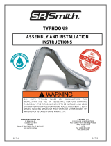
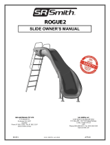
OWNER’S MANUAL
ASSEMBLY AND SET-UP INSTRUCTIONS
S.R.SMITH SLIDEAWAY SLIDES ARE MANUFACTURED FOR INSTALLATION AND USE ON INGROUND SWIMMING POOLS ONLY.
THE SLIDEAWAY IS NEVER TO BE INSTALLED AND USED ON ABOVEGROUND POOLS, ONGROUND POOLS, HOUSEBOATS,
BOAT DOCKS, FLOATING DOCKS OR PLATFORMS OR OTHER BODIES OF WATER SUCH AS LAKES, PONDS, RIVERS, ETC.
WARNING
06-804 | AUG22
I
N
D
E
P
E
N
D
E
N
T
L
Y
T
E
S
T
E
D
&
V
E
R
I
F
I
E
D
©
C
o
p
y
r
i
g
h
t
2
0
1
8
S
.
R
.
S
m
i
t
h
,
L
L
C
.
S
W
I
M
M
I
N
G
P
O
O
L
S
L
I
D
E
C
O
M
P
L
I
A
N
C
E
D
O
C
U
M
E
N
T
S
A
V
A
I
L
A
B
L
E
U
P
O
N
R
E
Q
U
E
S
T
SAFETY
100%
COMPLIANCE
For children
up to 125 lbs.

2 3
Contents
INTRODUCTION . . . . . . . . . . . . . . . . . . . . . . . .3
WARNINGS AND SAFETY SUMMARY . . . . . . . . . . . . . 4
INTENDED USE INSTRUCTIONS . . . . . . . . . . . . . . . . 5
STRUCTURAL & INSTALLATION CHECKLIST . . . . . . . . . .6
ASSEMBLY AND INSTALLATION . . . . . . . . . . . . . . . .7
ASSEMBLED SLIDEAWAY LAYOUT . . . . . . . . . . . . . . 8
PARTS LIST . . . . . . . . . . . . . . . . . . . . . . . . . . 9
SLIDE ASSEMBLY INSTRUCTIONS . . . . . . . . . . . . . . 10
SLIDE SETUP INSTRUCTIONS . . . . . . . . . . . . . . . . . 11
HOSE ASSEMBLY INSTRUCTIONS . . . . . . . . . . . . . . 13
WARRANTY & PRODUCT REGISTRATION INFORMATION . . 16
INTRODUCTION
DANGER – FAILURE TO FOLLOW THESE WARNINGS, INSTRUCTIONS, AND THE OWNER’S
MANUAL MAY RESULT IN SERIOUS INJURY OR DEATH.
The SlideAway® is designed and manufactured for installation and use on in-ground residential
swimming pools only. Do not install this slide on above ground pools, houseboats, boat docks,
oating
docks or platforms, or other bodies of water such as lakes, ponds, rivers, etc. Proper assembly,
installation, use, and supervision are essential for proper operation and to reduce the risk of
serious injury or death.
All national and local building codes must be followed. This includes any applicable requirements for
size of concrete footing, overall height of slide, and bonding or electrical codes.
Check inside all boxes and packaging materials for parts. Before beginning assembly, read all
instructions and identify parts using the gures and parts listed in this document. It is critical that all
parts be carefully inspected by the installer prior to installation to ensure that no damage occurred
in transit and that a damaged part is not used. Proper installation cannot be overstressed, improper
installation voids S.R.Smith’s warranty and may aect the safety of the user.
Installer must give the slide owner the SlideAway Owner’s Manual, and answer all questions
regarding safe and proper use and slide maintenance.
Visit SlideAway.com for an Installation Video
and FAQ to ensure the proper set-up and use
of your SlideAway®

4 5
WARNINGS AND SAFETY SUMMARY
DANGER-FAILURE TO FOLLOW THESE WARNINGS, INSTRUCTIONS AND THE
OWNER’S MANUAL MAY RESULT IN SERIOUS INJURY OR DEATH.
HEAD FIRST SLIDES ARE STRICTLY PROHIBITED
TO REDUCE THE POSSIBILITY OF INJURY, IT IS NECESSARY THAT THE USER KNOW THAT THE CHIEF
DANGER OF HEAD FIRST SLIDING IS SERIOUS SPINAL INJURY. INJURIES TO THE SPINE MAY RESULT IN
TEMPORARY OR PERMANENT PARALYSIS OR EVEN DEATH. RESEARCH STUDIES HAVE SHOWN THAT
YOU CANNOT RELY ON THE WATER TO SLOW YOU DOWN SUFFICIENTLY TO AVOID INJURY.
DO NOT
SLIDE
HEAD
FIRST
DANGER
INTENDED USE INSTRUCTIONS
The SlideAway® slide is designed and manufactured for installation and
use on inground swimming pools only. Do not install the SlideAway
slide on above ground pools, houseboats, boat docks, oating docks
or platforms, or other bodies of water such as lakes, ponds, rivers,
etc. Proper assembly, installation, use, and supervision is essential for
proper operation and to reduce the risk of serious injury or death.
1. The SlideAway slide must be placed on the pool in a location that meets the requirements of manufacturer’s
placement instructions on pages 13, 14, and 15.
2. The SlideAway slide ladder must be lled to the minimum water ll line when the slide is in use. The water level
must be checked daily to make sure the water is at the correct level.
3. SlideAway support brace must be installed when the slide is in use.
4. Slide feet rst only as shown in Figure 1. Do not slide head rst.
5. Only one person allowed on the slide at a time with a maximum user weight of 125 lb (56.7 Kg).
6. Adult supervision required at all times when children are using the slide.
7. Hold onto handrails at all times when using the ladder.
8. No roughhousing or horseplay on slide.
9. Do not jump or dive from any part of the slide.
10. Familiarize yourself with the shape of the pool bottom and the water depth before you slide.
Slide feet rst only.
11. Do not slide until all submerged obstacles, surface objects or other swimmers are clear of the slider’s pathway.
12. Do not use the slide while under the inuence of alcohol or drugs.
13. Don’t slide alone; use the buddy system.
14. Take your time in preparing to slide. Move forward slowly and get yourself positioned properly
before starting the slide.
15. Only persons healthy enough for water activities should use the slide. Persons with medical conditions, including
pregnancy, should consult their doctor before using the slide. Persons with physical disabilities
should use caution and may require assistance.
16. Do not use the slide if any part of it becomes damaged, weakened, or broken. Have the slide inspected
and, if necessary, repaired by a pool professional, who is familiar with water slides before using the slide.
See installed slides’ structural & installation checklist.
READ AND FOLLOW ALL SAFETY RULES LISTED
BELOW.
MAKE SURE THAT EVERYONE WHO USES THE
SLIDEAWAY KNOWS AND FOLLOWS ALL RULES.
CHILDREN MUST BE SUPERVISED BY AN ADULT
AT ALL TIMES WHEN USING THE SLIDE.
WARNING

6 7
PROPER SLIDING POSITION
Slide users must use the sitting slide position, facing forward, feet
rst as shown in Figure 1.
STRUCTURAL & INSTALLATION CHECKLIST
After installation and prior to the rst use of the SlideAway® and periodically (see DAILY/WEEKLY MAINTENANCE OF
THE SlideAway) thereafter the owner must:
1. Inspect the runway for visible cracks or tears.
2. Inspect the ladder for sharp edges, protrusions, cracks or tears.
3. Inspect slide assembly for loose corroded fasteners.
4. Measure the following dimensions and compare with the manufacturer’s placement instructions on pages
13, 14, and 15.
5. Pool water depth at the base of the slide should be at least 3' (914 mm) deep, and at 4'6" (1372 mm) out from
slide exit, should be at least 4'6" (1372 mm) deep.
6. The height of the slide runway exit above the water should be 20" (508 mm) maximum.
7. The distance between the slide centerline and the edge of other pool equipment should be at least 3'6"
(1067 mm).
8. Observe the position of the exit of the slide as shown in Figures 8, 9 and 10 on pages 13 and 14.
9. Read, understand and enforce all safety and use instructions on the slide.
Figure 1
DAILY/WEEKLY MAINTENANCE OF THE SLIDEAWAY
1. When hosing down the deck, hose your SlideAway® to wash away any dust, dirt or other debris,
which may have accumulated.
2. Be sure that all connections are secure. Tighten hardware if necessary.
3. Polyethylene parts require little maintenance. Hose and wipe to clean.
4. While cleaning slide, check and see that all nuts and bolts are tight and secure.
5. Inspect the runway for visible cracks or tears, sharp edges and protrusions.
6. Inspect all attachment points for loose or corroded fasteners.
7. Inspect all ladder tread or step-attachment points for evidence of shear, bending yield, or fatigue
in the ladder steps, rails, or attachments means. Yield is evidenced by crystallization or ne cracking
of the ladder tread and/or surface.
8. Inspect the ladder handrails for rigidity and attachment.
APPLICABLE STANDARDS AND CODES
The installation of the SlideAway must comply with all applicable governmental and building codes.
ASSEMBLY AND INSTALLATION
All S.R.Smith SlideAway slides are inspected prior to shipment from the factory. Proper assembly, installation,
and placement is mandatory. Improper assembly and installation voids S.R.Smith’s warranty and may aect the
safety of the user. It is the installer’s responsibility to ensure the structural integrity of the concrete pad prior to
installation of the slide.
DRAWINGS
All drawings in this Slide Owner’s Manual are for illustration purposes only and are NOT TO SCALE.
SUBSEQUENT OWNERS
The Owner’s Manual must remain with the owner of the slide. If the owner changes, the Owner’s Manual
shall be brought to the attention of the new owner.

8 9
ASSEMBLED SLIDEAWAY LAYOUT
Figure 2
PARTS LIST
ITEM # PART # DESCRIPTION QUANTITY
1 660-209-5820-A SlideAway SLIDE ASSEMBLY 1 ea.
2 660-209-5820-C SlideAway SUPPORT BRACE 1 ea.
3 660--209-5820-D SlideAway WATER CAP 1 ea.
4 05-715 PVC Plug SCH 80 ¾" NPT 2 ea.*
5 05-711 PVC Nipple SCH 80 ¾" x 2" 1 ea.
6 05-796 ¾" 90 Degree Elbow 1 ea.
7 05-713 ¾" Hose Clip 3 ea.*
8 05-642 Hose Clip Screw, #8 X 1.5" 18-8 SS 3 ea.*
9 05-797 Garden Hose Swivel Adapter 1 ea.
10 40-1000 Dolly 1 ea.
* Additional items included in kit are for replacements in case items are misplaced. Visit srsmith.com for hardware
kit and replacement part information.
7
8 9
1
2
34 5
6
10

10 11
SLIDE ASSEMBLY INSTRUCTIONS
Prior to starting assembly, check and make sure that all components listed
on the parts list on page 9 were included in the package.
Assembly Steps
1. Place the provided dolly under the bottom step of the ladder as shown
in Figure 3.
2. Once dolly is in place, use your foot to ensure that the dolly is rmly
positioned in place (see Figure 4).
3. Using both hands, as shown in Figure 5, grab the ladder handles and
slowly begin leaning the SlideAway towards you to transfer the weight of
the slide onto the dolly wheels, enabling you to roll the slide to the desired
location.
4. Once you have rolled the SlideAway into the desired location, place your
foot back onto the base of the dolly to secure it and carefully lean the
SlideAway back up until it is free-standing again.
5. Remove the dolly and store it away until you are ready to move your
SlideAway o of the pool deck.
6. To insert brace, slightly lean SlideAway to one side using the ladder
handles as shown in Figure 6. Slide the brace under the slide and lock
rmly into place (Figure 7).
Figure 3
Figure 4
Figure 5 Figure 6 Figure 7
3.50
SLIDE EXIT ALIGNMENT
POOL EDGE
LINE
8.89
MANUFACTURER’S PLACEMENT INSTRUCTIONS
PROPER ASSEMBLY, INSTALLATION, USE, AND
SUPERVISION ARE ESSENTIAL FOR PROPER
OPERATION AND TO REDUCE RISK OF
SERIOUS INJURY.
1. The critical dimensions for placement of the
SlideAway® are shown in Figures 13, 14 and 15.
A. The red lines on the sides of the runway exit
must be aligned with, or overhanging the pool
edge, see Figure 13.
SLIDE SETUP INSTRUCTIONS
1. Place the assembled slide on the deck in a location that meets the requirements detailed in Manufacturer’s
Placement instructions on pages 13, 14 and 15. The Slide may be angled slightly providing all dimensions are
maintained as noted in the Manufacturer’s Placement Instructions. The red lines on the sides of the runway
exit warning label must be aligned with, or overhanging the edge of the pool (Figure 13).
2. Once the slide is in the proper location on the deck, the support brace must be installed and the ladder
must be filled with water to provide stability to the slide prior to use.
3. Insure proper installation of the support brace as instructed in Slide Assembly Instructions on page 10
(see Figures 6 and 7). The support brace must be installed prior to lling the ladder with water.
4. The slide must not be used unless the ladder is filled with
water up to the minimum fill line, see Figure 12.
5. Install the plug (4) into the drain hole shown in Figure 12.
It is recommended to use a thread sealant or Teon tape on
the threads to prevent leaking. To ll the ladder with water,
remove the ll cap (3) by turning counter clockwise and
pulling outward to remove. Remove the cap and ll ladder
base with water up to the minimum ll line. Replace the cap
by inserting into the hole and turning clockwise to lock into
place.
6. Once the ladder is lled with water the slide cannot be
moved. To remove the water from the ladder, unscrew the
plug and allow to drain.
Figure 12
Figure 13

12 13
B. The slide exit runway surface shall not exceed 20" (51 cm) above the water surface as shown in Figure 14.
C. The slide shall be positioned so that all water owing o the runway exit drops into the pool. The
recommended overhang is 3.5" (9 cm) minimum.
D. The minimum depth of water below the exit lip of the slide shall be 3' (91 cm) and increase to 4'6"
(137 cm) at Pt. A, which is a distance of 4'6" (137 cm) from the exit lip of the slide as shown in Figure 14.
E. A minimum depth of 4'6" (137 cm) shall be maintained at a distance of 9' (274 cm) along the extended
centerline of the slide from Pt. A. as shown in Figure 14.
2. A minimum clearance area in front of the slide shall always be maintained as follows:
A. The minimum clearance distance on either side of the extended
centerline of the slide runway shall not be less than 3'6"
(107 cm) at a point no less than 2'6" (76 cm) from the exit lip
of the slide and extending a distance of 13'6" (411 cm) in front
of the slide as shown in Figure 15.
MANUFACTURER’S PLACEMENT
INSTRUCTIONS
Figure 14
Figure 15
HOSE ASSEMBLY INSTRUCTIONS
Tools Required
Phillips head screwdriver
Teon tape or thread sealant
Assembly Steps
1. Thread the nipple (5) into 90˚ elbow (6) as shown in
Figure 8. It is recommended to apply a thread sealant or
Teon tape to the threads to prevent leaking.
2. Install assembled nipple (5) and elbow (6) into the
threaded hole in the left side of the runway.
3. Turn the assembled nipple (5) and elbow (6) until the
open end of the elbow tting is pointing back toward the
bottom of the stairs as shown in Figures 9 and 11.
4. Install the garden hose thread adapter (9) into the open
end of the elbow tting (6) as shown in Figure 8. It is
recommended to apply a thread sealant or Teon tape to
the threads to prevent leaking.
5. Locate the dimple on the left side of the ladder as shown in Figure 9. Place the hose clip screw (8) through the
hole in the hose clip (7). Align the screw with the dimple in the ladder, and install the screw into the ladder side
wall. Tighten until snug making sure not to overtighten the screw.
6. Install the second hose clip in the recess on the back side of the ladder shown in Figure 10.
Figure 9
90 DEGREE ELBOW
PVC NIPPLE
GARDEN HOSE
ADAPTER
5
6
9
Figure 8

14 15
7. Attach the water supply hose to the garden hose adapter.
8. To place the hose into the hose clips, open the hose clip and place the hose within the jaws of the clip.
Hold the hose above and below the clip and push the hose rmly towards the back of the clip until the
jaws lock together.
9. Turn on the water and adjust the ow rate as required.
Figure 10
Figure 11
FOR POOLS WITH DIVING BOARD ALREADY INSTALLED
The minimum clearance area in front of a properly installed diving board on an inground swimming pool is a
minimum distance of 3'6" (107 cm) on either side of the board’s centerline as shown in Figure 16. Pt. C extends a
minimum distance of “C” from the tip end of the board as shown in Table 1 and Figure 16. The width distance “W”
on either side of Pt. C is given in Table 1 and shown in Figure 16.
Board Minimum Clearance Area
Pool Type “C” Dimension “W” Dimension
I 14' -6" (442 cm) 5' -0" (152 cm)
II 14' -6" (442 cm) 6' -0" (183 cm)
III 16' -6" (503 cm) 6' -0" (183 cm)
IV 18' -6" (564 cm) 7' -6" (229 cm)
V 21' -0" (640 cm) 7' -6" (229 cm)
Table 1
See Article 5 contained in ANSI/APSP/ICC-5 2011 STANDARD FOR RESIDENTIAL INGROUND SWIMMING
POOLS and refer to FIGURE 3 and Table 1 for Minimum Water Envelope Dimensions AB, BC and Width at
Point C.
“C” DIMENSION FOR BOARD = AB + BC
“W” DIMENSION FOR BOARD = WIDTH AT PT. C
The minimum clearance area of a slide or diving board shall not intersect any
coping or rope and oat line as shown in Figure 17.
The minimum clearance area of a slide or diving board may intersect each other
provided that they are not used simultaneously.
Figure 16
Figure 17

WARRANTY & PRODUCT REGISTRATION INFORMATION
For warranty information and details, please visit srsmith.com/warranty
Register your S.R.Smith product at srsmith.com/productregistration
A Fluidra Brand | srsmith.com | 800.824.4387
©Copyright 2022 S.R.Smith, LLC. All rights reserved.
No part of this may be copied or reproduced without the expressed written consent of S.R.Smith, LLC
0822
/