Page is loading ...

To avoid electrical shock, do not touch the lead tips and the circuit
under test during measurement.
To avoid damage to the instrument, insulation measurement must be
performed on de-energized circuits only. Make sure that the circuits or
equipment is disconnected before proceeding with an insulation test.
Connect the test leads to the instrument and the circuit under test.
Check the circuit under test is not energized as follows.
Connect the test leads to the circuit under test and read a voltage
value.
If the circuit is live, the meter indicates the voltage.
If the meter indicates V, the circuit is dead.
Press test button. Read the red megaohm scale directly.
Continuous Measurement
A lock down feature is incorporated on the test button. Pressing and
turning it clockwise lock the test button in the continuous operating
position.
To release the lock turn the test button counter clockwise.
Never leave the test button locked down when not in use.
Discharging capacitance of circuit under test.
It is possible that capacitance has been stored in the circuit under
test after insulation testing. To discharge the circuit capacitance
reverse the connection of the earth clip and line probe. Remaining
electric charges can be observed on AC voltage warning range.
Do not touch the circuit under test immediately after testing.
Capacitance stored in the circuit may cause electric shock.
This instruction manual contains warnings and safety rules that must
be observed by the user to ensure safe operation of the instrument
and retain it in safe condition. Therefore, read these operating
instructions thoroughly and completely before using the instrument.
The symbol on the instrument means that the user must refer to
the relevant section of this instruction manual for safe operation of
the instrument.
Pay particular attention to all WARNINGS and CAUTIONS in this
instruction manual. WARNING indicates warnings to avoid
electrical shock and CAUTION indicates cautions to avoid damage
to the instrument.
. Always make sure to insert the plug of test leads fully into the
terminal of the instrument.
. Never exceed the maximum allowable input of any measuring range
when making measurement.
. Make sure to never apply a voltage more than V AC or DC
between the terminal of the instrument and earth.
. Never try to operate the instrument in an explosive atmosphere ( i. e.
in the presence of flammable gases or fumes, vapor or dust).
. Always inspect the instrument, test leads and accessories for any
sign of damage or abnormality before every use. If abnormal
conditions exist (e. g. broken test leads, cracked enclosure of the
instrument), do not try to make measurements.
. Do not push the test button or lock it down while connecting test
leads.
. Do not touch the circuit under teat insulation testing.
. Make sure to remove the test lead from the instrument and turn the
power off before opening the battery compartment cover for battery
replacement.
. Always turn the power off after use.
. Do not expose the instrument to the direct sun, dew fall, or extreme
temperatures.
. Do not expose the instrument to a temperature of more than .
. Calibration and repair of any instrument should only be performed
by qualified and trained service technicians.
. Do not install substitute parts or perform any unauthorized
modification of the instrument. Return the instrument to your
distributor for service and repair to ensure that safety features are
maintained.
. The instrument must be used by a competent, trained person and
operated in strict accordance with the instructions. A.W.Sperry will
not accept liability for any damage or injury caused by misuse or
noncompliance with the instructions or safety procedures. It is
essential to read and understand the safety rules contained in the
instructions. They must be observed when using the instrument.
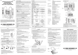
Fixing Screw
o avoid shock hazard disconnect the test leads from the
instrument.
To replace the batteries, first disconnect all test leads from the
instrument. Open the battery compartment cover by unscrewing the
metal captive screw to reveal battery compartment. The four .V SUM-
(R )type batteries are located in a compartment. Always replace all
four batteries with new ones at the same time. Never mix old and new
ones. Screw the battery compartment lid back on before using the
instrument.
Case lid can be fit under the housing case as illustrated bellow.
) Open the case lid as shown.
) Turn it degrees.
)
Put the case lid under the housing case.
) Hook it on to the housing case.
AC voltage measurement can be made without depressing the test
button.
Buttery check facility.
Uses only .V battery type R , AA or equivalent.
Measuring ranges accuracy(at , relative humidity -%)
Insulation resistance ranges:
AC Voltage Warning:
Power supply .V battery type SUM- ,R ,AA or equivalent
Overload protection Insulation Resistance Ranges
Model :V (DC+ACp-p) for seconds
Model :V (DC+ACp-p) for seconds
AC Voltage Range
V (DC+ACp-p) for seconds
Operating temperature -, relative humidity up to %
& humidity
Storage temperature - -, relative humidity up to %
& humidity
Withstand voltage V AC for one minute between electrical
circuit and housing case
Insulation resistance More than Mat V between electrical
circuit and housing case
Dimensions (L) (W) (D)mm
Weight g
Accessories Test leads Model (set)
Pouch for test leads ( piece)
Shoulder strap ( piece)
Rbatteries ( pieces)
Instruction manual ( copy)
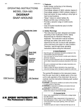
Test voltage
Measuring range
Mid-scale value
Output voltage on
open circuit
Output short
circuit current
Accuracy
MODEL
V
M
M
Rated test voltage + -
A max
- M :of reading
.of scale length at other measuring ranges
- M :
of reading
A max
MODEL
V
M
M
Warning range
Accuracy
-V AC
of scale length
Neck strap
Buckle
Buckle Fixing Button
Tighten
Strap
. Fit the neck strap as shown.
. Fit the test lead pouch to the housing case as shown.
Do not try to remove dirt on the meter cover by rubbing hard with a dry
cloth. This can remove anti-electrostatic agent applied to the surface of
the surface of the meter cover.
When the meter reading is affected by electrostatic build up on the meter
cover.
Wipe the meter cover surface using a cloth dampened with off-the shelf
anti-static agent or detergent.
To avid possible deforming or discoloring, do not use solvents.
To clean the body of the instrument, use cloth dampened with detergent.
Never use paint thinner, benzene or other solutions containing
solvents for cleaning the instrument.
Otherwise, deforming or discoloring of the instrument body or the
meter cover may result.
Teat Lead pouch
Mechanical zero adjustment
Without pressing the Test button, check that the pointer lines up
with the mark on the red megaohm scale. If not, adjust it by
rotating the movement zero adjust with a screwdriver.
Test lead connection
Insert the test leads into the terminals of the instrument.
Battery voltage check
Battery check LED flashes at insulation resistance testing to
indicate normal battery condition.
Replace the batteries when the LED stops flashing.
Replace the batteries according to section for battery replacement.
Test leads check
Press and turn the Test button to lock it down. When the test leads
are connected together, the pointer should move for from the
position towards the position on the megaohm scale. If not, the
leads may by faulty. Release the Test button after completion.
When the Test button is pressed, take care not to touch the tip of the
test lead where a high voltage is present in order to avoid possible
shock hazard.
Never depress the test button when voltage is present on the circuit
under test.
The presence of AC voltage can be detected. This function operates
automatically when the test button is not depressed, i.e., in the up
position.
Using the test leads, connect EARTH terminal to the earth side of
the circuit under test and LINE terminal to the line side.
Take the reading on the AC voltage scale.
Note:
Handle the instrument with care and follow the instructions in order to
maintain it in good condition for a long period of time.
The attention to detail of this fine snap-around instrument is further
enhanced by the application of A.W. Sperry,s unmatched service and
concern for detail and reliability. These A.W. Sperry snap-arounds are
internationally accepted by craftsmen and servicemen for their
unmatched performance. All A.W. Sperry,s snap-around instruments are
unconditionally warranted against defects in material and workmanship
under normal conditions of use and service; our obligation under this
warranty being limited to repairing or replacing free of charge, at A.W.
Sperry snap-around instrument that malfunctions under normal
operating conditions at rated use.
Securely wrap the instrument and its accessories in a box or mailing bag
and ship prepaid to the address below. Be sure to include your name and
address, as well the name of the distributor, with a copy of your invoice
from whom the unit was purchased, clearly identifying the model
number and date of purchase.
The warranty is not applicable if the instrument has been: misused,
abused, subjected to loads in excess of specifications, has had
unauthorized repair or has been improperly assembled or used.
*Note: Recommended calibration interval should not exceed one year.
Calibration service charges are not covered terms and conditions of
warranty.
/