Page is loading ...

84-9310028-02 Rev A
Operations Manual
Version 20.3.0
LVS® 7510
Integrated System

LVS-7510 Integrated System Operations Manual Version 20.3.0
LVS-7510 Integrated System Operations Manual Version 20.3.0 Page 2 of 212
Copyright ©2020
Omron Microscan Systems, Inc.
Tel: +1.425.226.5700 / 800.762.1149
All rights reserved. The information contained herein is proprietary and is provided solely for the purpose of allowing customers
to operate and/or service Omron Microscan-manufactured equipment and is not to be released, reproduced, or used for any
other purpose without written permission of Omron Microscan.
Throughout this manual, trademarked names are used. We state herein that we are using the names to the benefit of the
trademark owner with no intention of infringement. Microsoft
®
and Windows
®
are trademarks of Microsoft Corporation. Microsoft
product screen captures are reprinted with permission from Microsoft Corporation.
GS1 Solution Partner
Disclaimer
The information and specifications described in this manual are subject to change without notice.
Latest Manual Version
For the latest version of this manual, see:
automation.omron.com
Technical Support
For technical support, see:
ia.omron.com/support/
Warranty
For current warranty information, see:
ia.omron.com/product/cautions/common/agreements-before-purchase/index.html

LVS-7510 Integrated System Operations Manual Version 20.3.0
LVS-7510 Integrated System Operations Manual Version 20.3.0 Page 3 of 212
Table of Contents
Safety Instructions ........................................................................................................................ 5
Important Information ................................................................................................................... 5
Introduction .................................................................................................................................... 6
Software Modules ....................................................................................................................... 6
Functional Characteristics ........................................................................................................... 8
Modes of Operation ..................................................................................................................... 11
Design Mode ............................................................................................................................. 14
Production Mode ....................................................................................................................... 17
Log In ............................................................................................................................................ 20
Welcome Screen Overview ......................................................................................................... 22
Settings ..................................................................................................................................... 23
Administration............................................................................................................................ 25
Language .................................................................................................................................. 34
Log In ........................................................................................................................................ 34
About ......................................................................................................................................... 34
Design Mode: Create a New Template ...................................................................................... 35
Create a Template Using Automatic Setup ............................................................................... 36
Create a Template Using Manual Setup ................................................................................... 39
Design Mode: Load an Existing Template ................................................................................ 84
Design Mode: Retrieve a Template from Archive ..................................................................... 85
Design Mode: Ready to Run ....................................................................................................... 86
Make Ready Mode .................................................................................................................... 88
Production Mode: Import a New Job ......................................................................................... 89
AutoExecute Functionality ......................................................................................................... 90
Production Mode: Load an Existing Job ................................................................................... 91
Production Mode: Ready to Run ................................................................................................ 92
Make Ready Mode .................................................................................................................... 94
Design and Production Mode: Running .................................................................................... 95
Error Display ................................................................................................................................ 98
Blemish Error Display .............................................................................................................. 101
Reports / QC File Viewer ........................................................................................................ 102
Sample Reports ...................................................................................................................... 103
Preventive Maintenance ............................................................................................................ 109
Troubleshooting ........................................................................................................................ 109
Mechanical Diagrams ................................................................................................................ 110
LVS-7510 Basic Wire Diagram ............................................................................................... 110

LVS-7510 Integrated System Operations Manual Version 20.3.0
LVS-7510 Integrated System Operations Manual Version 20.3.0 Page 4 of 212
Appendix A: User Configurable Settings ................................................................................ 111
Settings Configuration Editor .................................................................................................. 111
List of User Configurable Settings........................................................................................... 113
Appendix B: Epedigree ............................................................................................................. 151
Appendix C: ImageSaver Instructions .................................................................................... 154
Saving Raw Images Without a Label Repeat ......................................................................... 154
Saving Images WITH a Label Repeat ..................................................................................... 158
Appendix D: Upgrading Software ............................................................................................ 162
Appendix E: Automatic Login .................................................................................................. 166
Automatic Login Settings ........................................................................................................ 166
Automatic Login Instructions ................................................................................................... 167
Appendix F: Managing Operator Permissions in Microsoft® Active Directory ................... 169
Overview ................................................................................................................................. 169
Enable Active Directory ........................................................................................................... 170
Active Directory User Permissions .......................................................................................... 179
Appendix G: TCP/IP Control ..................................................................................................... 181
TCP/IP Configuration Settings ................................................................................................ 181
TCP/IP Commands and Output Data Summary ..................................................................... 182
TCP/IP Commands Protocol ................................................................................................... 183
TCP/IP Output Data Protocol .................................................................................................. 189
Appendix H: LVS-7510 Printronix Integrated System ............................................................ 191
Printing Stopped Error Message ............................................................................................. 191
Foreground and Background Errors ....................................................................................... 192
Printing Timeout Error ............................................................................................................. 192
Reset the Printer ..................................................................................................................... 193
Customizing the “Printing Stopped” and “Manual Intervention Required” Messages ............. 194
Form Feed Button ................................................................................................................... 195
Appendix I: Print Job Button .................................................................................................... 196
Appendix J: Windows® Lockdown ........................................................................................... 199
Shut Down the System ............................................................................................................ 200
Unlock ..................................................................................................................................... 200
Appendix K: Using the LVS-7510 Comparator Function........................................................202
Installing ScanProof™ Software ............................................................................................. 202
Launching ScanProof™ Software ........................................................................................... 203

LVS-7510 Integrated System Operations Manual Version 20.3.0
LVS-7510 Integrated System Operations Manual Version 20.3.0 Page 5 of 212
Safety Instructions
This unit has been carefully designed to provide years of safe, reliable performance. However, as with all
electrical equipment, there are some basic precautions that you should follow to avoid personal injury or
damage to the system:
Before using the system, carefully read all the installation and operating instructions.
Observe all warning instruction labels on the system.
To protect your system from overheating, make sure no openings on the system are blocked.
Never insert anything into the openings of the system.
Do not use the system near water or spill liquid into it.
All components used to create your system are UL and CE approved. All circuits were designed to
incorporate maximum safety. However, any equipment using electrical voltages may cause personal
injury if improperly handled.
Do not attempt to work on the system with the main power lines connected.
Ensure that the AC power source matches the ratings listed for the system. If unsure, check with your
dealer or local utility provider.
Do not place the AC power cord where it can be stepped on. If the AC power cord becomes damaged
or frayed, replace it immediately.
Avoid looking directly into any system lights. If you need to examine the lights, or look at any
component near the lights, be sure to first turn off the lights. If the lights cannot be turned off, then wear
polarized sunglasses while examining the lights.
To avoid damaging the system, turn off and unplug the system before cleaning.
If the system ever needs repair, consult Omron Microscan or your Omron Microscan Distributor.
Important Information
•Due to continual product improvements, the product you receive may differ from the content outlined in
this guide. If you have questions about your product that are not covered in this guide, please contact your
Omron Microscan representative or Technical Support: ia.omron.com/support/
•The LVS-7510 Integrated System arrives to your site packaged in specially designed shipping cartons. Do
not discard the shipping cartons in case you must ship or store the system for any reason. Failure to use
these cartons when returning your product to Omron Microscan will void warranty.
•The LVS-7510 Integrated System supports Windows® 7 Professional, Windows® 8.1 Professional, and
Windows® 10 Professional.
•LVS-7510 includes technologies covered under United States Patent # 8,939,368 B2.

LVS-7510 Integrated System Operations Manual Version 20.3.0
LVS-7510 Integrated System Operations Manual Version 20.3.0 Page 6 of 212
Introduction
Software Modules
The LVS-7510 offers 100% print quality inspection and barcode verification for Thermal and Thermal
Transfer Printers. LVS-7510 features include:
Barcode Validation (Reading of 1D and 2D codes)
Barcode Verification (Grading of 1D and 2D codes to ISO/IEC Standards)
Master-to-Label Comparison (Blemish Detection)
Optical Character Recognition (OCR)
Optical Character Verification (OCV)
Number Validation
Data and Code Matching
The LVS-7510 is a modular system, which means that you can check the print quality for any of the
aforementioned areas, or for all of the areas. The features are listed below.
Important:
The maximum system speed is 10 inches per second.
The LVS-7510 uses a monochrome camera to capture images, which makes images appear in black
and white. Some images in this guide were captured with a color camera, so you will notice some
images with color.
Barcode Validation
The LVS-7510 decodes 1D (linear) and 2D (two-dimensional) codes (including ECC-200 Data Matrix, GS1
Data Matrix, Composite, QR Code, GS1 QR Code, PDF-417 and Micro PDF) and determines if the code is
“readable.” No attempt is made to grade the codes according to any standard. A check is made for presence
of a GS1 FNC1 character at the beginning of a GS1 type bar code.
Barcode Verification
The LVS-7510 verifies (decodes and grades) 1D (linear) and 2D (two-dimensional) codes including ECC-200
Data Matrix, Composite, QR Code, PDF-417 and Micro PDF symbologies according to the internationally
accepted rules of the applicable symbology specifications and ISO 15415 and 15416.
The LVS-7510 displays a “real-time” graph indicating the overall ISO grade, which allows the operator to see
trends in print quality for several hundred labels that were just inspected. When an error is detected, the
“real-time” graph changes color. The system can also be programmed to “stop the press” when an error
occurs (the appropriate hardware must be purchased for this feature).
Master-to-Label Comparison (Blemish Detection)
The Master-to-Label Comparison module, also referred to as blemish detection, identifies and tracks
potential print errors such as die cut errors, broken letters, skews, smears, spots, voids, wrinkles, missing
copy, and other print quality defects. The Master-to-Label Comparison module also includes an “ignore area”
function which accounts for variable image data within a pattern-matching zone and does not report them as
blemishes. All inspection is completed at thermal printer speeds up to 10 ips.
Note: The LVS-7510 uses red light (660 nm) to detect blemishes; thus, color blemishes in
the red spectrum may not be properly detected.

LVS-7510 Integrated System Operations Manual Version 20.3.0
LVS-7510 Integrated System Operations Manual Version 20.3.0 Page 7 of 212
IMPORTANT: The LVS-7510 is designed to inspect labels, record and display the results,
and supply optional signals to the printer or other external system. The LVS-7510 cannot
“stop”, “score out void” or “reprint” labels; these are functions that are the responsibility of
the printer. Be sure your printer has these necessary capabilities and interface connections
to utilize the output capabilities of the LVS-7510.
Optical Character Recognition (OCR)
Unlike the OCV Module, this module “reads” characters and reports the data content at font sizes as low as
six points (one point is defined as approximately 1/72
nd
of an inch or .35 mm). This data is typically variable
and the content remains unknown until it is read. It is important to note that the system can be trained to
know what to expect for every character position. In other words, the software can be programmed on what
characters to expect: alpha, numeric, or special characters. Many fonts are used in the printing industry. The
LVS-7510 is designed to learn new fonts as necessary. Refer to the “OCR and OCV Guidelines” section
below for more information.
Optical Character Verification (OCV)
The OCV module verifies human readable characters at font sizes as low as six points (one point is defined
as approximately 1/72
nd
of an inch or .35 mm). The LVS-7510 OCV module ensures that a string of
sequential alpha-numeric characters is verified against a known field or file. In other words, you program the
software to detect what characters should appear and the software reports if the characters actually
appeared. The software will also return a percentage score as to how well the character(s) matched to the
trained character(s). Refer to the “OCR and OCV Guidelines” section below for more information.
OCR and OCV Guidelines
Characters must not touch or overlap
All uppercase letters in any font are allowed
Lowercase letters, uppercase letters, and some special
characters are allowed in OCR-B MT font (6 to 14 points).
Shown to the right are the letters, numbers, and special
characters supported by OCR-B MT font (6 to 14 points)
Monospaced fonts, like OCR-B, are preferred and perform
better in the LVS-7510
Do not attempt to re-learn any of the supplied OCR-B MT
fonts
Number Validation
Verifies the expected order of any numerical series, detects duplicates and sequence errors, and matches
variable numbers with external data files.
Data and Code Matching
Verifies encoded data that represents human readable information and ensures synchronicity of multiple
fields within a label.
OCR-B font set

LVS-7510 Integrated System Operations Manual Version 20.3.0
LVS-7510 Integrated System Operations Manual Version 20.3.0 Page 8 of 212
Functional Characteristics
The characteristics listed below apply to the LVS-7510 5.4” (137 mm) and 8.5” (216 mm) readheads.
Line Scan Camera: 400 DPI. Floating Sensor Head
Light Source: Red Light. 660 nm
Inputs / Outputs: USB 2.0 port. 5-Volt Power Supply
Maximum System Speed: 10 inches (254 mm) per second
ISO Verification
Verify: Any combination of linear, matrix or stacked codes to ISO print quality
standards including:
Linear (1D) Verifier Conformance (ISO/IEC 15416)
2-Dimensional (2D) Verifier Conformance (ISO/IEC 15415)
Orientation & Number: Ladder or Pickett fence orientation and any number of codes on a
label.
Read and Analyze: 1D and 2D to published International specifications, with an overall
ISO (ANSI) grade.
Minimum Linear (1D) Narrow
Bar Width:
Read only: 6.3 Mils (.0063”) (.160 mm)
Verification: 8.8 Mils (.0088”) (.223 mm)
Minimum 2D Cell Size: Read only: 10.0 Mils (.0100”) (.254 mm)
Verification: 12.5 Mils (.0125”) (.317 mm)
Reporting: Detailed data to be reported is in .csv file format for extraction by the
end user. Immediate reporting is available for viewing via the monitor.
Optical Character Verification (OCV)
Minimum Human Readable: .083 inches / 2.12 mm / 6 Printer Points
Data: Verifies variable and fixed data ascending, descending or from a file.
Read or Verify: Sequential string of alphanumeric characters (numbers 0 to 9 and
letters A to Z) against known field or database. Guidelines:
Characters must not touch or overlap
All uppercase letters in any font are allowed
Lowercase letters, uppercase letters, and some special
characters are allowed in OCR-B MT font (6 to 14 points).
Shown to the right are the letters, numbers, and special
characters supported by OCR-B MT font (6 to 14 points)
Monospaced fonts, like OCR-B, are preferred and perform better
in the LVS-7510
Do not attempt to re-learn any of the supplied OCR-B MT fonts

LVS-7510 Integrated System Operations Manual Version 20.3.0
LVS-7510 Integrated System Operations Manual Version 20.3.0 Page 9 of 212
OCR-B font set
Blemish Detection
Print faults Detects skew, smear, print registration, die-cut errors, edge determination and
missing information.
Variable Data Allows user specified variable data within a pattern matching zone.
Red Light (660 nm) The LVS-7510 uses red light (660 nm) to detect blemishes; thus, color
blemishes in the red spectrum may not be properly detected.
Minimum point size Blemish Inspection: 5 Mils / .005” / .126 mm
Missing Period: 5 Mils / .005” / .126 mm
Number Validation
Validates numerical order requirements (ascending, descending, or alpha numeric series) to ensure
numbers are in the expected order
Use external data file for the validation of random number sequence
Detects duplicate numbers
Matching
Matches decoded data from a barcode to human readable text of that barcode
Matches multiple fields of data within the label area being inspected

LVS-7510 Integrated System Operations Manual Version 20.3.0
LVS-7510 Integrated System Operations Manual Version 20.3.0 Page 10 of 212
Supported Symbologies
Below are a few of the symbologies supported by the LVS-7510. Contact Omron Microscan for a full list of
supported symbologies.
Aztec
Codabar
Code 128
Code 39
Code 93
Data Matrix
DataBar expanded
EAN-13
EAN-13 (2-digit supplemental) Stacked
EAN-13 (5-digit supplemental)
EAN-8
ECC-200 Data Matrix
GS1-128
GS1 Databar Limited
GS1 Databar
GS1 Databar-14
GS1 Data Matrix
Interleaved 2 of 5 (ITF)
Laetus Pharmacode
Micro QR Code
PDF417
QR Code
UPC-A
UPC-A (2-digit supplemental)
UPC-A (5-digit supplemental)
UPC-E
UPC-E (2-digit supplemental)
UPC-E (5-digit supplemental)
All applicable GS1 composite components
International Standards
ISO/IEC 15415
ISO/IEC 15416
All supported ISO/IEC symbology specifications

LVS-7510 Integrated System Operations Manual Version 20.3.0
LVS-7510 Integrated System Operations Manual Version 20.3.0 Page 11 of 212
Modes of Operation
The LVS-7510 Integrated System software has two modes of operation: Design and Production modes.
The reason for the different modes is to support the segregation of duties and provide a productive and
secure environment for label production and validation.
Design and Production mode units are usually separate physical systems; however, it is possible to
configure one LVS-7510 system to operate in both modes and switch between Design and Production
modes when needed. The LVS-7510 is purchased as a Dual mode system. The software license codes are
to remain with the system hardware and are not transferable.
The primary differences between the two modes are that templates are created in Design mode only.
Templates are then promoted to production and become jobs. Production mode is used to execute the
promoted jobs. Highlights of each mode are listed below.
After user login, the Welcome screen displays the appropriate option buttons depending on the user’s
permissions and licensed modes of operation. The screen below shows a dual mode system that has
specific radio button controls to switch between Design and Production modes. The ability to switch between
modes is restricted to users who are assigned administrator permissions.

LVS-7510 Integrated System Operations Manual Version 20.3.0
LVS-7510 Integrated System Operations Manual Version 20.3.0 Page 12 of 212
Design mode option buttons:
Create a new template
Load an existing template
Retrieve template from archive
Production mode option buttons:
Import a new job
Load an existing job
Retrieve job from archive
Dual mode system with radio
button controls to switch between
Design and Production modes.

LVS-7510 Integrated System Operations Manual Version 20.3.0
LVS-7510 Integrated System Operations Manual Version 20.3.0 Page 13 of 212
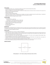
Example LVS-7510 Design and Production Mode Configuration

LVS-7510 Integrated System Operations Manual Version 20.3.0
LVS-7510 Integrated System Operations Manual Version 20.3.0 Page 14 of 212
Design Mode
The Design mode system is a sophisticated software package with many inspection capabilities. It is best
operated by a well-trained individual or group to ensure the final production process runs as automated as
possible with as little operator interaction as possible. Design mode is intended to eliminate the set-up
process on the production line.
The Design mode system is a complete system that includes the LVS-7510 inspection unit, computer and
client printer. The system can be setup anywhere on the client’s network allowing multiple designers to share
template designs.
The process of capturing a Golden Image is through a physical printout of a mock production run of labels.
The mock production labels are printed and variable data attributes are tested in the Design mode.
If the optional PDF compare feature is enabled, the Design operator can compare the golden image against
an approved PDF using the supplied PDF comparison software. The comparison process is as simple as
loading an approved PDF from a folder location on the network and clicking “Play” from within the template
Design mode. The software runs a comparison against the captured golden image and highlights any
differences for the operator to review. Once satisfied that the PDF and Golden image match, the operator
clicks “Accept” and a report is stored with the job for any future reference. If any discrepancies are found, the
operator simply reprints a new image on the LVS-7510 and runs the comparison again.
Note: The LVS PDF Comparator Kit, previously offered by Omron Microscan, is no longer available. A
similar product is available from Global Vision Inc.: https://www.globalvisioninc.com/. Omron Microscan
does not provide support services for software purchased from Global Vision Inc.
In Design mode, more than one template can be active and available to the operator, who is trained in the
design and creation of the label inspection templates. A new template is created by clicking the “Create a
new template” button. A message box appears requesting the new template name to be created.
The template name is given to the folder where the LVS-7510 will create and save all files involved in the
execution of an actual production template. After design is complete, the designer will close out the template,
which zips up all files and stores them as one .zip file in the Archived folder of the Design mode LVS-7510.
Archived templates can be retrieved and activated allowing designers to update, copy and reuse previous
designs.
In Design mode, the LVS-7510 utilizes two job-related file folders for a specific purpose. The default naming
of the folders is based on their purpose, but can be changed to suit the client’s requirements. All folders can
be on a mapped network drive or local drive for each LVS-7510 system.

LVS-7510 Integrated System Operations Manual Version 20.3.0
LVS-7510 Integrated System Operations Manual Version 20.3.0 Page 15 of 212
Define Template Path Locations in Design Mode
You must define where templates are located on a network drive or local folder. This section explains how to
configure the LVS-7510 path locations for the following:
Template folder:
In Design mode, this is where new templates are created and designed. Multiple templates under
development are allowed.
A new template is initiated by creating a new folder with the new job name in the Jobs folder.
Archived folder:
In Design mode, templates that are complete and closed out are zipped up and removed from the
Template folder to the Archived templates folder. The jobname.zip file is ready for execution in
Production mode or recall back into Design mode for changes and/or updates.
Define Location of Templates and Archive folders:
IMPORTANT: You must have administrator rights to perform the steps in this section.
1. Log in to the LVS-7510 software.
2. Click “Settings” in the menu bar.
3. In “Settings for this section,” click the drop-down box and select “Paths.”
4. In the “Setting” column, double-click either “DesignTemplates” or “Design Archive.”
5. In the “Value” field, enter the path and then click “OK (save changes).” For example, by default the
value \Design\Templates will store templates on the local LVS-7510 computer.
For installations of software version 20.2.X on Windows® 7 Professional, Windows® 8.1 and
Windows 10 Professional operating systems: C:\LvsData\LVS 7500\Design\Templates.
Jobs created in earlier versions of the software are not supported. Manually backup any desired data
and manually delete the C:\Users\[User Login Name]\AppData\Roaming\Label Vision Systems\LVS

LVS-7510 Integrated System Operations Manual Version 20.3.0
LVS-7510 Integrated System Operations Manual Version 20.3.0 Page 16 of 212
7500 or C:\Users\[User Login Name]\AppData\Roaming\Microscan\LVS 7510. Then, install software
release 20.2.X as a new installation.
6. Click “OK (save changes).”
7. Repeat steps 4 and 5 to set the DesignArchive path setting.

LVS-7510 Integrated System Operations Manual Version 20.3.0
LVS-7510 Integrated System Operations Manual Version 20.3.0 Page 17 of 212
Production Mode
In Production mode, the LVS-7510 can be configured based upon the PC network implementation and level
of operator interaction desired.
Define Job Path Locations in Production Mode
In Production mode, the LVS-7510 utilizes the following folders:
Import folder
In Production mode, new jobs waiting to be executed are dropped into the Import folder. When a
designer executes a “Promote template to production,” the template is copied into the Production Import
folder. Multiple jobs can reside in the Import folder waiting to be acted on by the production operator.
This folder can be located on a network drive or local folder.
Jobs folder
In Production mode, the operator will select a job from the Import folder to be executed. The job is
unzipped and a folder is created in the Jobs folder with the job name. Only one job can reside in the
Jobs folder. To clear the active job from the Jobs folder the production operator must execute “Close
out job” which zips up the job along with run related data. The executed jobname.zip file is copied into
the Production Archive folder. The job is deleted from the Jobs folder to make ready for the import of a
new job. For Job Auto-Execute functionality, see page 90.This folder can be located on a network drive
or local folder.
Output folder
In Production mode, when a job is completed and closed out, the output reporting and summary file(s)
are written to this folder path. This folder can be located on a network drive or local folder.
Archive folder
This folder contains the detailed production data for a job that includes the inspection results for each
label. Jobs that are complete and closed out are zipped up and moved from the Jobs folder to the
Archive folder. This folder can be located on a network drive or local folder.

LVS-7510 Integrated System Operations Manual Version 20.3.0
LVS-7510 Integrated System Operations Manual Version 20.3.0 Page 18 of 212
Define Location of Production folders
IMPORTANT: You must have administrator rights to perform the steps in this section.
1. Log into the LVS-7500 software.
2. Click “Settings” in the menu bar.
3. In “Settings for this section,” click the drop-down box and select “Paths.”
4. In the “Setting” column, double-click one of the production path settings (such as ProductionImport).
5. In the “Value” field, enter the path and then click “OK (save changes).” For example, by default the
value \Production\Import will store templates on the local LVS-7510 computer.
For installations of software version 20.2.X on Windows® 7 Professional, Windows® 8.1 and
Windows 10 Professional operating systems: C:\LvsData\LVS 7500\Production\Import
Jobs created in earlier versions of the software are not supported. Manually backup any desired
data and manually delete the C:\Users\[User Login Name]\AppData\Roaming\Label Vision
Systems\LVS 7500 or C:\Users\[User Login Name]\AppData\Roaming\Microscan\LVS 7510. Then,
install software release 20.2.X as a new installation.

LVS-7510 Integrated System Operations Manual Version 20.3.0
LVS-7510 Integrated System Operations Manual Version 20.3.0 Page 19 of 212
6. Click “OK (save changes).”
7. Repeat steps 4 through 6 to set the ProductionJobs, ProductionOutput and ProductionArchive path
setting.

LVS-7510 Integrated System Operations Manual Version 20.3.0
LVS-7510 Integrated System Operations Manual Version 20.3.0 Page 20 of 212
Log In
Follow the steps below to log in to the LVS-7510.
Note: Users with the “Automatic Login” feature enabled bypass the Welcome screen and
automatically access the Welcome screen where they are able to work according to the
system setup and their individual permissions (as shown in step 3 below showing the Design
Mode Welcome Screen). Refer to “Appendix E: Automatic Login” for more information on
using the “Automatic Login” feature.
1. Start the LVS-7510 software. The Welcome screen appears (see below).
2. Click the Log In button. The Login box appears. Enter the Operator ID and Password, and then click
OK.
When using the LVS-7510 for the first time, enter Admin in both fields (Operator ID field and
Password field).
Refer to the Operators section for detail instructions on creating operator IDs and password
(Welcome Screen Overview Administration Operators)
/