Page is loading ...

CDP 40-50-70 & CDP-T 40-50-70
SERVICE MANUAL
en Rev. 1.4 • 2021-W12-4


3
Introduction: Table of contents
Introduction
Table of contents
Introduction .....................................................................3
Table of contents ......................................................................3
Overview .............................................................................4
Declaration of Conformity .............................................................5
Product description ..............................................................6
Overall description ....................................................................6
Enclosure dimensions ................................................................10
Technical data. . . . . . . . . . . . . . . . . . . . . . . . . . . . . . . . . . . . . . . . . . . . . . . . . . . . . . . . . . . . . . . . . . . . . . . . 11
Installation. . . . . . . . . . . . . . . . . . . . . . . . . . . . . . . . . . . . . . . . . . . . . . . . . . . . . . . . . . . . . . . . . . . . . 12
Installation environment .............................................................12
Wall mounting .......................................................................13
Electrical connection .................................................................18
Operation. . . . . . . . . . . . . . . . . . . . . . . . . . . . . . . . . . . . . . . . . . . . . . . . . . . . . . . . . . . . . . . . . . . . . . 21
Control panel ........................................................................21
Maintenance and care .......................................................... 23
Preventative maintenance . . . . . . . . . . . . . . . . . . . . . . . . . . . . . . . . . . . . . . . . . . . . . . . . . . . . . . . . . . . . 23
Software update and log les .........................................................24
Trouble shooting .....................................................................26
Spare parts. . . . . . . . . . . . . . . . . . . . . . . . . . . . . . . . . . . . . . . . . . . . . . . . . . . . . . . . . . . . . . . . . . . . . . . . . . . 29
Schematics. . . . . . . . . . . . . . . . . . . . . . . . . . . . . . . . . . . . . . . . . . . . . . . . . . . . . . . . . . . . . . . . . . . . . 30
Cooling circuit .......................................................................30
Main PCB ............................................................................31
Wiring diagram ......................................................................32
en

4
Introduction: Overview
Overview
The target group for this service manual is the technicians who install and maintain the CDP
40-50-70 and CDP 40T-50T-70T dehumidier. Thus the manual covers instructions about
installation, operation and maintenance.
It is the responsibility of the operator to read and understand this service manual and other
information provided and to use the correct operating procedure.
Read the entire manual before the initial start-up of the unit. It is important to know the cor-
rect operating procedures for the unit and all safety precautions to prevent the possibility of
property damage and/or personal injury.
It is the responsibility of the installer to ensure the conformity of all, not supplied cables
towards national regulations.
Copying of this service manual, or part of it, is forbidden without prior written permission
from Dantherm.
Dantherm reserves the right to make changes and improvements to the product and the
service manual at any time without prior notice or obligation.
The unit is designed to last for many years. When the time comes for the unit to be recycled, it
should be recycled according to national rules and procedures to protect the environment.
The CDP dehumidiers contain R407C refrigerant and compressor oil. The compressor must
be returned to authorities for disposal according to local regulations.
Type and source of hazard
This symbol in connection with the word “Danger” warns of a high risk or severe injury or
acute danger to life.
• Measures to avert danger or immediate measures if the risk occurs are described in this
way
Type and source of hazard
This symbol in connection with the word “Warning” warns of a risk involving severe injury.
• Measures to avert danger or immediate measures if the risk occurs are described in this
way
Type and source of hazard
This symbol in connection with the word “Caution” warns of a risk of minor or moderate injury
and material damage.
• Measures to avert danger or immediate measures if the risk occurs are described in this
way
In connection with this symbol you will nd further tips and information concerning the use
of the device.
Target group
Safety precautions
Copyright
Reservations
Recycling
Warning
Caution
DANGER
Warning
Caution
WARNING
Warning
Caution
CAUTION
!NOTICE

5
Introduction: Declaration of Conformity
Declaration of Conformity
Dantherm hereby, declare that the unit mentioned below:
No.: 351510, 351516, 351511, 351517, 351512 & 351518
Type: CDP 40, CDP 40T, CDP 50, CDP 50T, CDP 70 & CDP 70T
- complies with the following directives:
2006/42/EC Machinery Directive
2014/30/EU EMC Directive
2011/65/EU RoHS Directive
1907/2006/EC REACH Regulation
- and is manufactured in compliance with the following harmonized standards:
DS/EN ISO 12100-2010 Safety of machinery - General principles for design
EN 60 335-1:2012 Household and similar electrical appliances - Safety - Part 1
EN 60 335-2-40:2003 Household and similar electrical appliances - Safety - Part 2-40
EN 60335-2-40: A1 2006 Household and similar electrical appliances - Safety - Part 2-40
EN 378-1:2016 Refrigerating systems and heat pumps
- Safety and environmental requirements - Part 1
EN 378-2:2016 Refrigerating systems and heat pumps
- Safety and environmental requirements - Part 1
Skive, 18.03.2021
Declaration
Jakob Bonde Jessen
Managing director
Mikkel Haldrup Jensen
Project manager designer
en

6
Product description: Overall description
Product description
Overall description
This illustrates the functional principle of the CDP 40-50-70.
CDP
CDP -T
Fig. 1
CDP 40-50-70 and CDP 40T-50T-70T work in accordance with the condensation principle.
Humid air from the pool room is drawn into the unit by one or two fans.
When passing through the evaporator the air is cooled down to below dew point and water
vapour is condensed into water, which is drained.
The dry air is then passed through the condenser where it is heated and returned to the pool
room. As a result of the latent heat from the condensation process and the compressor en-
ergy the return air temperature to the pool room is approx. 5ºC higher than the air from the
pool room.
Air ow direction
Functionality of
the dehumidier

7
Product description: Overall description
When the dehumidier is started by the hygrostat, the fan(s) are activated at the same time as
the compressor.
In order to check the humidity level the units are starting the fan(s) once an hour for one
minute (NOTE: only applicable to CDP 40T-50T-70T units):
• If the humidity is above the selected setpoint, the unit starts dehumidifying.
• If the humidity is below the setpoint, the unit will remain o and check the humidity
level again after one hour.
To protect the compressor against overloading there is a timer which prevents the dehu-
midier from starting more than 10 times pr hour. It means, that there is at least 6 minutes
between every start up.
This unit is equipped with an intelligent defrosting strategy.
The unit monitors the temperature of the evaporator, and when the temperature has been
below a certain temperature for a period of time, the dehumidier will switch to active
defrosting, the fans will stop, and the magnetic valve will open.
The hot gas can now pass through the evaporator.
When the evaporator has the right temperature again the magnet valve will close and the
dehumidication will continue.
If the temperature in the dehumidier increases to a temperature of more than 55 °C (in case
of fan failure or room air temperature higher than 36 °C), the compressor stops automatically
to avoid damaging it. When the temperature allows it the dehumidication will continue.
B
A2
A1
Two cable grooves for accessory make it
easy to guide the cables from the control
panel to the mains electricity connection
and out of the unit.
Groove B is for use with cable from ex-
ternal RH sensor as it requires a seperate
groove to avoid interference.
All other accessory cables are to be
placed in groove A1-A2.
An LED is placed at the front of the unit. The LED light
indicates dierent modes of the unit.
Find a description of the dierent modes in section
“LED light and troubleshooting” on page 27.
Fan control
Compressor
control
Defrosting
Safety circuit
Cable groove
(accessory)
LED
en

8
Product description: Overall description
Pos. Part Illustration
1 LED lamp
2 Air outlet
3 Air inlet
4 Drip tray
5 Control panel
(behind the cover)
6 Cable groove
(for accessory only)
7 Humidity sensor
8 Wall mounting
spacers
(incl. in delivery)
9 Mains electricity
connection
(behind the lid)
10 Wall bracket
11 Water drain
CDP
Presentation
Fig. 2
5
4
7
6
Inside (front cover removed)
1
3
Front cover
2
Rear view
10
8
9
11
Bottom view

9
Product description: Overall description
Pos. Part Illustration
1 LED lamp
2 Control panel
(behind a cover)
3 Drip tray
4 Cable groove
(for accessory only)
5 Wall bracket
6 Mains electricity
connection
(behind the lid)
7 Air outlet
8 Humidity sensor
9 Air inlet
10 Water drain
CDP-T
Presentation
Fig. 3
1
Front cover
9
Rear view
7
5
8
3
2
4
Inside (front cover removed)
9
10
Bottom view
en

10
Product description: Enclosure dimensions
Enclosure dimensions
Fig. 4
Fig. 5
CDP 40-50-70
CDP 40T-50T-70T

11
Product description: Technical data
Technical data
Specication unit CDP 40 CDP 40T CDP 50 CDP 50T CDP 70 CDP 70T
Operating range,
humidity %RH 40-100 40-100 40-100 40-100 40-100 40-100
Operating range,
temperature °C 10-36 10-36 10-36 10-36 10-36 10-36
Air volume at max.
external pressure m/h 400 400 680 680 900 900
Capacity at 28ºC - RH 60 l/day 34 34 52 52 69 69
SEC 28ºC - RH 60 kWh/l 0,47 0,47 0,48 0,48 0,43 0,43
Power supply V/Hz 1 × 230/50 1 × 230/50 1 × 230/50 1 × 230/50 1 × 230/50 1 × 230/50
Max. power
consumption kW 0.9 0.9 1.5 1.5 1.8 1.8
Max Ampere
consumption A 3,8 3,8 6,6 6,6 8 8
Refrigerant -R407C
Quantity of refrigerant kg 0.7 0.7 0.9 0.9 1.2 1.2
GWP (Global Warming
Potential) -1774
Noise level* (1 m from
unit) dB(A) 46 43 47 44 50 47
Weight kg 56,5 57,5 65,0 66 75,5 77,5
Filter Type PPI 15
Protection class IPX4
Data sheet
en

12
Installation: Installation environment
Installation
Installation environment
The correct combination of chemicals in an indoor swimming pool is crucial, both for the
health of users and for the inventory inside the pool room and the swimming pool’s technical
room. Insuciently treated water results in poor hygiene, while water that has been exces-
sively treated results in gases in the air that contain chlorine, which can irritate the eyes and
cause breathing diculties.
At the same time, the incorrect composition of chemical ingredients in the water can destroy
all of the inventory in a very short space of time, including the dehumidier and other equip-
ment that have been installed to process the air.
Shown below are the threshold values, which apply to products for indoor swimming pools
in accordance with EN/ISO 12944-2, protection class C4. These threshold values must be com-
plied with for the warranty to be valid.
The following guideline values are applicable to swimming pools with the addition of chemi-
cals.
Chemicals ppm
Free chlorine content 1.0-2.0
Combined chlorine content Max. 1/3 of free chlorine content
pH 7.2-7.6
Total alkalinity 80-150
Calcium hardness 250-450
Total dissolved solids < 2000
Sulphates < 360
The following guideline values are applicable to swimming pools with self-production of
chlorine:
Chemicals ppm
Salt (NaCl) < 30,000
Total dissolved solids < 5500
pH 7.2-7.6
Total alkalinity 80-150
Calcium hardness 250-450
Sulphates < 360
It is advisable to use the Langelier Saturation index to ensure that the combination of the
dierent water parameters is acceptable.
Contact Dantherm A/S if necessary.
• The CDP 40T-50T-70T units are designed for installation in a heated room, adjacent to the
pool room.
• Do not place the dehumidier close to a heating source, e.g. a radiator.
• Doors and windows must be kept closed when the dehumidier is in function.
• To make sure that the room air passes freely through the dehumidier, air inlet and air
outlet openings must be free.
Water quality in
indoor pools
When adding
chemicals
With own
production of
chlorine
Langelier
Saturation index
Optimal
conditions
!NOTICE

13
Installation: Wall mounting
Wall mounting
Please follow this procedure to mount the CDP 40-50-70:
(Go to page 15 for instructions on wall mounting of the CDP-T range)
Step Description Illustration
1 Find the right spot for the CDP
dehumidier and measure
where the wall suspension bar
has to be mounted.
Recommended distance from
dehumidier to:
• Ceiling: min 225 mm
• Floor: min 225 mm
Min. 225 Min. 225 198
Min. 727
A
2 Fix the wall suspension bar sup-
plied with the unit to the wall.
NB: It is important to x it
horizontally to ensure correct
condensate outlet.
Mounting
CDP 40-50-70
en

14
Installation: Wall mounting
3 Fasten the two wall mounting
spacers (included in the deliv-
ery) on the back of the unit.
2x
4Drain outlet:
Connect a drain hose and make
a condensate outlet through
the wall.
Connect a 3/4” exible or xed
water hose to the spigot at the
base of the dehumidier. Make
sure the drainage has a drop of
at least 2 %.
Alternatively:
• A condensate pump can be
tted at the water outlet in
order to pump the water to
a drain.
5 Hang the dehumidier on the
wall suspension bar.
!

15
Installation: Wall mounting
Please follow this procedure to mount the CDP 40T-50T-70T:
(Go to page 13 for instructions on wall mounting of the CDP 40-50-70 units)
Step Description Illustration
1 Find the right spot
for the CDP-T dehu-
midier and meas-
ure where the wall
suspension bar has
to be mounted.
Fix then the wall
suspension bar sup-
plied with the unit
to the wall.
NB: It is important
to x it horizontally
to ensure correct
condensate outlet.
CDP 40T CDP 50T CDP 70T
Y437 341 450
2 Make a hole in the
wall according to
the measurements
of the illustration.
CDP 40T CDP 50T CDP 70T
Z610 760 1095
Mounting
CDP 40T-50T-70T
Warning
Caution
Y
Y
68
110
110
Z
395
en

16
Installation: Wall mounting
3 Use CDP-T wall duct
in order to seal be-
tween unit and wall.
See how to mount
the wall duct cor-
rectly in the CDP-T
wall duct instruc-
tion.
4 Fasten the two wall
mounting spacers
(included in the de-
livery) on the back of
the unit.
2x
5Drain outlet:
Connect a drain
hose and make a
condensate outlet
through the wall.
Connect a 3/4” ex-
ible or xed water
hose to the spigot
at the bottom of the
dehumidier. Make
sure the drainage
has a drop of at least
2 %.
Alternatively:
• A condensate pump can be tted at the water outlet in order to pump the water
to a drain.
CDP-T wall duct
Instruction
?
Wall duct for CDP 40T-50T-70T
INSTRUCTION
Rev. 1.2 • 2019-W38-5
dcba
!

17
Installation: Wall mounting
6 Hang the dehu-
midier on the wall
suspension bar.
Warning
Caution
en

18
Installation: Electrical connection
Electrical connection
Risk of damaging the dehumidier, if it has been lying down.
The compressor can be damaged permanently, when the unit is started up just after it has
been lying down.
• Wait 1 hour with the start up of the dehumidier, if the unit has been lying down (e.g.
during transport or installation).
Risk of electric shock
An electric shock can cause severe burning and in most extreme cases shock to the brain,
strain to the heart, injury to other organs or result in death.
• Switch o the power on the main switch, while you open the dehumidier.
• Remember also to switch o the power, while you close the dehumidier.
Step Description Illustration
1 Loosen the two screws that
secure the lid to the mains
electricity connection. Tilt the
lid in order to get access to the
terminals.
2 Guide the cable for the power
supply through the PG cable
restrainer.
3 Connect the power to the unit in
accordance with the description
stated on the name plate.
See also “Wiring diagram” on
page 32.
4 Close the lid and x it with screws again.
Warning
Caution
CAUTION
Warning
Caution
DANGER
Connection of
power supply
2,5 mm
Min Ø9
Max Ø18

19
Installation: Electrical connection
It is the responsibility of the installer to ensure the conformity towards national regulations of
all, not supplied cables.
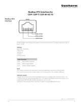
The interfaces and terminals on the control panel make it possible to communicate with the
dehumidier and connect accessory such as a RH/T sensor, an alarm and a heating coil. The
gure and table below describe the dierent functions of the interface.
+v
TH
TH
GND
GND
+
GND
+
RH
ON
ON
USB RS485 EXT RH/T ALARM 12V DC
RUN FAIL HEAT1 HEAT2
GND
+
GND
+
RH
ON
ON
OK
1 2 3 4 5
Fig. 6
Pos. Interface Description
1 USB USB is used for datalogging/ software update. See more information
in section “Software update and log les” on page 24.
2 Modbus RTU
(RS-485)
Connection via modbus. A list of data for the Modbus interface can be
downloaded on support.dantherm.com
3 External
RH/T sensor
Terminals for connecting an external humidity/ temperature sensor.
See wiring example in Fig. 7
4 Alarm An external alarm can reveal, if the dehumidier is operating normally
or has an error. See wiring example in Fig. 8
512 VDC
Heat control
Connection of LPHW (water) or electric heating helps controlling the
indoor temperature. Contact your Dantherm dealer for more informa-
tion.
There is an option for connecting an external RH/T sensor, which makes it possible to overrule
the internal sensors. In Fig. 7 there is an example on how it could be connected.
Fig. 7
*Switch in position: 0 = Internal sensors in use, 1 = External sensors in use
**Note, operational range is within 40-99% RH, if out of range the dehumidier will be in
stand by mode
!NOTICE
Control panel
interfaces
External RH/T
sensor connection
(Optional)
External temperature sensor
(or resistor)
ON/OFF switch for
external sensors*
(Optional)
EXT RH/T
External humidity sensor
(or control unit)
EXT RH/T
V+
TH
TH
RH
GND
10kΩ NTC
0V = 0% RH
5V = 50% RH
10V = 100% RH**
0
1
GND
0-10V
en

20
Installation: Electrical connection
There is an option for connecting an external alarm, which makes it possible to see, when the
dehumidier is operating normally or has an error. In order to use this option you must create
your own external electrical circuit and connect it to the run/fail terminal on the main PCB
(see page 31).
This illustration is an example of how the run/fail circuit could be used.
RUN FAIL
1234
VDC
(Max. 50V, 500mA)
GND
GND
VDC (Max. 50V, 500mA)
RUN FAIL
1234
VDC (Max. 50V, 500mA)
GND
GND
VDC (Max. 50V, 500mA)
NORMAL MODE ERROR MODE
Operational Mode
RUN FAIL
Error Mode
RUN FAIL
Fig. 8
Alarm
Run/ fail
connection
(Optional)
/