Page is loading ...

©Copyright Task Force Tips LLC 1999-2021 1 LIZ-010 January 13, 2021 Rev13
TASK FORCE TIPS LLC
MADE IN USA · tft.com
3701 Innovation Way, Valparaiso, IN 46383-9327 USA
800-348-2686 · 219-462-6161 · Fax 219-464-7155
G-Force
INSTRUCTION FOR INSTALLATION, OPERATION, AND MAINTENANCE
See section 3.2 for Flow/Pressure Operations Envelope
PROTECTOR™ STATION
MONITOR SERIES
DANGER
Understand manual before use. Operation of this device without understanding the manual and
receiving proper training is a misuse of this equipment. Obtain safety information at tft.com/
serial-number.
This equipment is intended for use by trained and qualified emergency services personnel for
firefighting. All personnel using this equipment shall have completed a course of education
approved by the Authority Having Jurisdiction (AHJ).
This instruction manual is intended to familiarize firefighters and maintenance personnel with the
operation, servicing, and safety procedures associated with this product. This manual should be
kept available to all operating and maintenance personnel.
Shown with Optional Valve

©Copyright Task Force Tips LLC 1999-2021 2 LIZ-010 January 13, 2021 Rev13
DANGER
PERSONAL RESPONSIBILITY CODE
The member companies of FEMSA that provide emergency response
equipment and services want responders to know and understand the
following:
1. Fire¿ ghting and Emergency Response are inherently dangerous activities
requiring proper training in their hazards and the use of extreme caution
at all times.
2. It is your responsibility to read and understand any user’s instructions,
including purpose and limitations, provided with any piece of equipment
you may be called upon to use.
3. It is your responsibility to know that you have been properly trained in
Fire¿ ghting and /or Emergency Response and in the use, precautions, and
care of any equipment you may be called upon to use.
4. It is your responsibility to be in proper physical condition and to maintain
the personal skill level required to operate any equipment you may be
called upon to use.
5. It is your responsibility to know that your equipment is in operable
condition and has been maintained in accordance with the manufacturer’s
instructions.
6. Failure to follow these guidelines may result in death, burns or other
severe injury.
FEMSA
Fire and Emergency Manufacturers and Service Association
P.O. Box 147, Lynn¿ eld, MA 01940 • www.FEMSA.org

©Copyright Task Force Tips LLC 1999-2021 3 LIZ-010 January 13, 2021 Rev13
TABLE OF CONTENTS
1.0 MEANING OF SAFETY SIGNAL WORDS
2.0 SAFETY
3.0 GENERAL INFORMATION
3.1 SPECIFICATIONS
3.2 OPERATING ENVELOPE
3.3 USE WITH SALT WATER
3.4 VARIOUS MODELS AND TERMS
3.5 INLETS AND OUTLETS
3.5.1 INLET FLANGES
3.5.2 OUTLET OPTIONS
3.6 OVERALL DIMENSIONS
4.0 INSTALLATION
4.1 STRUCTURAL REQUIREMENTS
4.2 NOZZLE INSTALLATION
4.3 PRESSURE GAUGE PORT
4.4 HANDLE INSTALLATION
4.5 DRAINING RESIDUAL WATER
5.0 OPERATING INSTRUCTIONS
5.1 VALVE OPERATION
5.2 HORIZONTAL ROTATION CONTROL
5.3 ELEVATION CONTROL
6.0 FLOW CHARACTERISTICS
6.1 AUTOMATIC NOZZLES
6.2 MST-4NJ STACKED TIPS FLOW AND REACH
6.3 EFFECTS OF ELEVATION AND WIND ON STREAM REACH
6.4 PRESSURE LOSS
6.5 STREAM STRAIGHTENERS
6.5.1 STREAM STRAIGHTENERS WITH STACKED TIPS
6.5.2 STREAM STRAIGHTENERS WITH FOG NOZZLES
7.0 WARRANTY
8.0 MAINTENANCE
8.1 SERVICE TESTING
8.2 REPAIR
8.3 LOWER SEAL AND VALVE SEAT REPAIR
8.4 UPPER SWIVEL AND SWIVEL INSERT REPAIR
9.0 EXPLODED VIEWS AND PARTS LISTS
10.0 OPERATION AND INSPECTION CHECKLIST

©Copyright Task Force Tips LLC 1999-2021 4 LIZ-010 January 13, 2021 Rev13
1.0 MEANING OF SAFETY SIGNAL WORDS
A safety related message is identified by a safety alert symbol and a signal word to indicate the level of risk involved with a particular
hazard. Per ANSI Z535.6, the definitions of the four signal words are as follows:
2.0 SAFETY
DANGER
DANGER indicates a hazardous situation which, if not avoided, will result in death or serious injury.
WARNING
WARNING indicates a hazardous situation which, if not avoided, could result in death or serious
injury.
CAUTION CAUTION indicates a potentially hazardous situation which, if not avoided, could result in minor
or moderate injury.
NOTICE
NOTICE is used to address practices not related to physical injury.
DANGER
An inadequate supply of pressure and/or flow will cause an ineffective stream and can result
in injury or death. Choose operating conditions to deliver adequate fire suppression. See flow
graphs.
WARNING
This equipment is intended for use by trained personnel for firefighting. Use of this equipment for
other purposes may involve hazards not addressed by this manual. Seek appropriate guidance and
training to reduce risk of injury.
WARNING
Injury or damage can occur from an inadequately supported monitor. The mounting must be
capable of supporting the nozzle reaction force.
WARNING
The stream exiting a nozzle is very powerful and capable of causing injury and property damage.
Make sure the nozzle is securely attached and pointing in a safe direction before water is turned on.
Do not direct water stream to cause injury or damage to persons or property.
WARNING
Equipment may be damaged if frozen while containing significant amounts of water. Such damage
may be difficult to detect visually. Subsequent pressurization can lead to injury or death. Any time
the equipment is subject to possible damage due to freezing, it must be tested and approved for
use by qualified personnel before being considered safe for use.
NOTICE
To prevent mechanical damage, do not drop or throw equipment.

©Copyright Task Force Tips LLC 1999-2021 5 LIZ-010 January 13, 2021 Rev13
3.0 GENERAL INFORMATION
The Task Force Tips Protector is a simple and rugged fixed station monitor with many unique features. Its patented waterway gives low
friction loss and delivers water to the nozzle with fewer twists and turns than a conventional monitor. The optional built-in on/off valve
with position indicator eliminates the need to add a costly valve to the monitor installation. The Protector is capable of flowing up to 1250
gpm (4800 L/min) while maintaining a FULL 360° rotational ability. The lever-action rotational lock is activated in one motion, visually
confirmed, and securely holds the monitor’s horizontal position. The Protector can be directly bolted to many common pipe flanges. The
outlet is available with various 2.5” (65 mm) male threads. The simple and basic design requires no grease application or other
maintenance. Swiveling elements and seals (including valve seat) can be replaced within a few minutes with common hand tools. All
models are equipped with an automatic drain valve to fully drain the monitor after each use. A threaded pipe port (1/4” NPT) (6 mm) is
provided for pressure gauge installation.
3.1 SPECIFICATIONS
.0
Table 3.1
3.2 OPERATING ENVELOPE
Nozzle A flows 500 gpm (1900 l/min), at 100 psi (7 bar), K factor = 50
Nozzle B flows 750 gpm (2800 l/min), at 100 PSI (7 bar), K factor = 75
Nozzle C flows 1000 gpm (3800 l/min), at 100 PSI (7 bar), K factor = 100
Nozzle D flows 1250 gpm (4800 l/min), at 100 PSI (7 bar), K factor = 125
Figure 3.2A
MANUAL
US METRIC
Weight (with optional shut off valve) 35.2 lbs 15.7 kg
Weight (without optional shut off valve) 27.8 lbs 12.5 kg
Minimum Flow Area 4.36 in228.1 cm2
Maximum Operating Pressure 250 psi 17 bar
Maximum Flow 1250 gpm 4800 l/min
Operating Temperature Range of Fluid 33°F to 120°F / 1°C to 50°C
Storage Temperature Range -40° to 150°F / -40° to 65°C
Materials ANSI A356.0-T6 Aluminum, 6000-series Aluminum,
18-8 Stainless Steel, Nylon, acrylonitrile rubber,
Dupont Alcryn 2080BK
WARNING
Damage or injury could result from operating the monitor beyond the safe operating envelope. Do
not operate the monitor outside the envelope in the following graph(s).
0 1000 2000 3000 4000 5000
0
2
4
6
8
10
12
14
16
18
20
0
25
50
75
100
125
150
175
200
225
250
275
300
0 250 500 750 1000 1250 1500
Flow Rate (l/min)
Monitor Inlet Pressure (bar)
Monitor Inlet Pressure (psi)
Flow Rate (gpm)
Protector Safe Operating Envelope
Nozzle B
Nozzle D
Nozzle A Nozzle C
Do not exceed
Maximum Monitor Inlet Pressure
Do not exceed
Max. Monitor
Flow Rate

©Copyright Task Force Tips LLC 1999-2021 6 LIZ-010 January 13, 2021 Rev13
3.3 USE WITH SALT WATER
Use with salt water is permissible provided the equipment is thoroughly cleaned with fresh water after each use. The service life of the
equipment may be shortened due to the effects of corrosion, and is not covered under warranty.
To reduce galvanic corrosion, it is highly suggested to use galvanic isolator kits between the monitor & mounting flange. Order Part # Z-
G4A150 (4") or Z-G3A150 (3").
3.4 VARIOUS MODELS AND TERMS
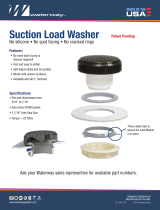
The Protector monitor is available in several different models and inlet connections. The two body styles are shown below.
The Monsoon Monitor comes in manual and electric remote control le d mode ls. Man ual models are available wi on both axis or a tiller bar model that uses a ti ll er bar to control horizontal rotation. Electric remote control models are ava ilab le in a standard model (suitable for on top of pumpers), a La dde r model and a Platform model. The Ladder or Platform model has a s mal ler swing radius and has horizontal travel stops factory installed at 90° le ft and rig ht (180° total).trol
Figure 3.4A
Figure 3.4B
Protector with Shut Off Valve Protector without Shut Off Valve
Serial Number
Flanged Base
Direction Control Handle
Elevation Locking Knob
Automatic Drain Valve
(See Section 4.5)
Horizontal Rotation Locking Lever
Port for Pressure Gauge 1/4" NPT
Valve Handle
Valve Position Indicator
Elevation Swivel
Threaded
Exit
Horizontal Swivel

©Copyright Task Force Tips LLC 1999-2021 7 LIZ-010 January 13, 2021 Rev13
3.5 INLETS AND OUTLETS
There is a wide variety of inlet and outlet options for the Protector monitor. Monitor height varies depending on whether the flange inner
diameter is 4” (100 mm) or 3” (80 mm), as shown below. Monitor height is measured from the bottom of the inlet flange to the centerline
of the elevation swivel.
3.5.1 INLET FLANGES
Table 3.5.1
3.5.2 OUTLET OPTIONS
Three options are available for the 2.5 inch male threaded outlet:
• National Hose Thread (NH, also referred to as National Standard Thread)
• National Pipe Straight Hose (NPSH, also referred to as Iron Pipe Thread)
• British Standard Pipe Thread (BSP)
3.6 OVERALL DIMENSIONS
Figure 3.6A
Inlet Flange Option Monitor Height
(inlet to elevation swivel)
Height at +30° Elevation Maximum Height at
+80° Elevation
3” ANSI 125/150
(also DN80 PN20)
16.2 in (41.1 cm) 24.7 in (62.7 cm) 31.0 in (78.7 cm)
DN80 P16 16.2 in (41.1 cm) 24.7 in (62.7 cm) 31.0 in (78.7 cm)
4” ANSI 150
(also DN100 PN20)
19.1 in (48.5 cm) 27.6 in (70.1 cm) 33.9 in (86.1 cm)
DN100 PN16 19.1 in (48.5 cm) 27.6 in (70.1 cm) 33.9 in (86.1 cm)
16.1"
[408mm] 19.1"
[485mm]
80°
27.7"
[703mm]
70°
11.3"
[288mm]

©Copyright Task Force Tips LLC 1999-2021 8 LIZ-010 January 13, 2021 Rev13
4.0 INSTALLATION
The Protector station monitor is installed to a riser pipe by a bolted flange joint. Verify that no interference exists between the Protector
and surrounding hardware that would limit its usefulness. If a valve is to be mounted under the Protector, verify that no interference
exists with the valve handle. If a butterfly valve is to be mounted under the Protector, verify that no interference exists between the
butterfly and the flanged base of the Protector when the valve is in its open position.
4.1 STRUCTURAL REQUIREMENTS
The structure that the monitor is mounted to must withstand the internal
pressure of the monitor as well as shear and bending forces due to nozzle
reaction. Nozzle reaction can be as high as 1050 lbs (480 kg) (1250 gpm at
250 psi).
For flanged connections, the use of flat flanges without raised faces is
recommended. Use a ring gasket as defined in ASME 16.21 or ISO 7483.
Tighten flange bolts in an alternating sequence as shown below. Tighten
sequentially each bolt or stud three times to 30%, then 60%, and finally
100% of the specified torque. Tighten to a total of 76-80 ft-lb (100-110 N·m).
Table 4.1
4.2 NOZZLE INSTALLATION
The nozzle is simply screwed onto the monitor’s exit threads.
WARNING
Reaction forces generated by master stream flows are capable of causing injury and property
damage if not properly supported. Monitors should be securely installed by qualified individuals.
• Mounting objects must be capable of withstanding maximum nozzle reaction force listed in
SPECIFICATIONS.
• The monitor must be securely mounted to rigid support members.
• Do not use flanges or pipe made from plastic for monitor mounting.
• Torque all fasteners to specified values.
NOTICE
If equipped with a TFT Corrosion Isolation Sleeve, the use of a gasket on either side of the sleeve is
required. Do not use a TFT Corrosion Isolation Sleeve as a gasket replacement.
FLANGE TYPE OPTION # OUTSIDE
DIAMETER
THICKNESS BOLT HOLE
CIRCLE
# OF
BOLTS
SIZE OF
BOLTS
in mm in mm in mm in mm
3” ANSI 125/150-DN80 PN20 1 7.5 190 0.75 20 6.0 152.5 4 5/8 16
4” ANSI 150-DN100 PN20 2 9.0 230 0.94 23 7.5 190 8 5/8 16
DN80, PN16 Flange 4 7.9 200 0.87 22 6.3 160 8 5/8 16
DN100, PN16 Flange 5 8.7 220 0.87 22 7.1 180 8 5/8 16
CAUTION Mismatched or damaged waterway connections may cause equipment to leak or uncouple under
pressure. Failure could result in injury. Equipment must be mated to matched connections.
CAUTION Dissimilar metals coupled together can cause galvanic corrosion that can result in the inability to
uncouple the connection, or complete loss of engagement over time. Failure could cause injury. Per
NFPA 1962, if dissimilar metals are left coupled together, an anti-corrosive lubricant should be
applied to the connection and the coupling should be disconnected and inspected at least
quarterly.
1
3
2
4
1
5
3
7
2
6
4
8
Tighten Sequentially Each Bolt Three Times
to a Total of 76-80 ft-lb (100-110 N·m)
Figure 4.1

©Copyright Task Force Tips LLC 1999-2021 9 LIZ-010 January 13, 2021 Rev13
4.3 PRESSURE GAUGE PORT
There is a ¼” NPT female threaded hole adjacent to the
elevation swivel. The hole is plugged from the factory. If a
pressure gage is desired, unscrew the plug and install the
gage using pipe sealant. Make sure the gage does not
interfere with operation.
4.4 HANDLE INSTALLATION
For tiller models, the handle is shipped loose from the
monitor and must be installed to complete the installation
process. When installing the tiller handle, be sure to coat
the threads of the mounting screw with the Loctite
supplied in the hardware packet.
4.5 DRAINING RESIDUAL WATER
All Protector station monitors are equipped with an automatic drain valve attached to a port located just above the valve seat and/or
lower seal. The automatic drain valve ensures the monitor is completely drained following use, which minimizes susceptibility to damage
from corrosion and freezing water. The drain valve seal membrane is designed to close automatically when pressure exceeds 5 psi.
When pressure drops below 5 psi, the seal membrane will open to allow drainage. If the automatic drain valve is omitted or disabled,
then the monitor must be manually drained after use to prevent damage.
WARNING
Monitors, valves, and piping may be damaged if frozen while containing sufficient amounts of
water. Such damage may be difficult to detect visually and can lead to possible damage, injury, or
death. Equipment that may be exposed to freezing conditions must be drained immediately
following use to prevent damage.
CAUTION Structural damage from corrosion can result from failure to drain appliance between uses. Damage
from corrosion can cause injury due to equipment failure. Always drain appliance between uses.
NOTICE
All monitors, valves and standpipes exposed to freezing conditions must be drained immediately
following use to prevent damage. To drain a standpipe, a drainage port must be opened
underground below the frost depth to keep water out of the standpipe until the next use.
Pressure Gage Port
1/4" NPT
Handle Mounting Screw
Figure 4.3

©Copyright Task Force Tips LLC 1999-2021 10 LIZ-010 January 13, 2021 Rev13
5.0 OPERATING INSTRUCTIONS
5.1 VALVE OPERATION
For models equipped with a built-in valve, the flow is OFF when the valve handle is horizontal and ON when the handle is vertical. The
valve is manufactured so that it cannot be assembled out of phase. A position indicator shows the valve position as “OFF” or “ON”. The
position that the valve is normally left in will depend upon your particular location’s standard operating procedure.
5.2 HORIZONTAL ROTATION CONTROL
To rotate the Protector from side to side on its swivel base:
1. Lift the rotation lock lever
2. Rotate the monitor right or left using the directional control handle.
To lock the monitor in position:
1. Depress the rotation lock lever.
A small spring holds the rotation lock lever in the unlocked position when it
is disengaged. When the monitor is not in use, the rotation lock lever should
be kept in the locked position.
5.3 ELEVATION CONTROL
To change the up and down direction (elevation) of the stream:
1. Push or pull vertically on the directional control handle.
To lock the monitor in position:
1. Twist the elevation locking knob clockwise to increase the drag on the
upper swivel joint and “lock” the monitor at a particular elevation.
WARNING
Sudden changes in valve position can cause pressure spikes (water hammer) and could lead to
hose failure or an out of control monitor. Open and close the valve slowly to avoid water hammer.
WARNING
Debris in the nozzle may cause off center nozzle reaction. Injury or damage from spinning or
sudden movement of the monitor could occur. To reduce the risk of an out of control monitor:
• Always check for waterway obstructions before flowing water
• Always keep the rotation lock tight when not rotating the monitor
• Always keep one hand on the tiller handle when loosening the rotation lock
• When 360° rotation is not needed, install horizontal rotation stop bolts to limit monitor travel
NOTICE
Select discharge devices that do not exceed the 70 ft-lb locking capability of the elevation lock. For
a typical fog nozzle, the maximum allowable weight is about 40 lbs (18.1 kg).
Rotation
Lock
Elevation
Lock
Directional Control
Handle
Figure 5.2

©Copyright Task Force Tips LLC 1999-2021 11 LIZ-010 January 13, 2021 Rev13
6.0 FLOW CHARACTERISTICS
6.1 AUTOMATIC NOZZLES
Automatic nozzles maintain a constant pressure by adjusting their orifice to match the available flow. Consult the nozzle manufacturer
for maximum flow and pressure range. In all cases do not exceed 1250 gpm (4800 L/min) and 250 psi (17 bar).
6.2 MST-4NJ STACKED TIPS FLOW AND REACH
Figure 6.2A
Table 6.2
NOZZLE INLET PRESSURE
NOZZLE
DIAMETER
40 PSI 60 PSI 80 PSI 100 PSI
FLOW
(GPM)
REACTION
(LBS)
FLOW
(GPM)
REACTION
(LBS)
FLOW
(GPM)
REACTION
(LBS)
FLOW
(GPM)
REACTION
(LBS)
1.375” 360 120 440 180 500 240 560 300
1.5” 420 140 520 210 500 280 670 350
1.75” 580 190 700 290 810 380 910 480
2.00” 750 250 920 380 1000 500 1190 630
NOZZLE INLET PRESSURE
NOZZLE
DIAMETER
2.8 BAR 4.1 BAR 5.5 BAR 7 BAR
FLOW
(L/min)
REACTION
(KG)
FLOW
(L/min)
REACTION
(KG)
FLOW
(L/min)
REACTION
(KG)
FLOW
(L/min)
REACTION
(KG)
35 mm 1360 50 1670 80 1890 110 2120 140
38 mm 1590 60 1970 100 2270 130 2540 160
45 mm 2200 90 2650 130 3070 170 3440 220
50 mm 2840 110 3480 170 4010 230 4500 290
2" 1-3/4" 1-1/2" 1-3/8"
2.5”
Coupling
Figure 6.2B
0.0
0.2
1.2
1.0
0.8
0.6
0.4
PRESSURE (BAR)
0
20
40
60
80
100
120
140
160
180
200
0 200 400 600 800 1000 1200 1400 1600
FLOW (GPM)
PRESSURE (PSI)
0 1000 2000 3000 4000 5000 6000
(LPM)
1 3/8" TIP
1 1/2" TIP
2" TIP
STACK TIP PERFORMANCE
(PRESSURE IS NOZZLE EXIT PITOT PRESSURE)
1 3/4" TIP

©Copyright Task Force Tips LLC 1999-2021 12 LIZ-010 January 13, 2021 Rev13
Figure 6.2C
0
20
40
60
80
0.0 40.0 80.0 120.0 160.0 200.0 240.0 280.0
40 PSI
60 PSI
100 PSI
80 PSI
HORIZONTAL DISTANCE (FEET)
VERTICAL DISTANCE (FEET)
VERTICAL DISTANCE (M)
0.040.0 80.0
0.060.02
HORIZONTAL DISTANCE (M)
2 INCH TIP
0
10
20
0
20
40
60
80
0.0 40.0 80.0 120.0 160.0 200.0 240.0 280.0
40 PSI
60 PSI
100 PSI
80 PSI
HORIZONTAL DISTANCE (FEET)
VERTICAL DISTANCE (FEET)
VERTICAL DISTANCE (M)
0.040.0 80.0
0.060.02
HORIZONTAL DISTANCE (M)
1.75 INCH TIP
0
10
20
0
20
40
60
80
0.0 40.0 80.0 120.0 160.0 200.0 240.0 280.0
40 PSI
60 PSI
100 PSI
80 PSI
HORIZONTAL DISTANCE (FEET)
VERTICAL DISTANCE (FEET)
VERTICAL DISTANCE (M)
0.040.0 80.0
0.060.02
HORIZONTAL DISTANCE (M)
1.50 INCH TIP
0
10
20
0
20
40
60
80
0.0 40.0 80.0 120.0 160.0 200.0 240.0 280.0
40 PSI
60 PSI
100 PSI
80 PSI
HORIZONTAL DISTANCE (FEET)
VERTICAL DISTANCE (FEET)
VERTICAL DISTANCE (M)
0.040.0 80.0
0.060.02
HORIZONTAL DISTANCE (M)
1.375 INCH TIP
0
10
20

©Copyright Task Force Tips LLC 1999-2021 13 LIZ-010 January 13, 2021 Rev13
6.3 EFFECTS OF ELEVATION AND WIND ON STREAM REACH
This graph shows approximately how differences in elevation angle can affect stream reach. Critical applications should be tested in
actual conditions to verify adequate reach.
This graph shows approximately how a moderate wind can affect stream reach.
Figure 6.2A
0 40 80 120 160 200 240 280 320
0
20
40
60
80
100
120
140
160
VERTICAL DISTANCE (FEET)
HORIZONTAL DISTANCE (FEET)
800604020
20
40
0
HORIZONTAL DISTANCE (METERS)
VERTICAL DISTANCE (METERS)
2.0 INCH TIP, 100 PSI, 1190 GPM
60 DEGREES
30 DEGREES
45 DEGREES
75 DEGREES
Figure 6.2B
0
10
40
20
80
040 80 120 160 200 240 280 320 360
HORIZONTAL DISTANCE (FEET)
2.00 INCH TIP, 100 PSI, 1190 GPM
VERTICAL DISTANCE (FEET)
NO WIND
TAILWIND
20 MPH (32 km/h)
HEADWIND
20 MPH (32 km/h)
0015705520
VERTICAL DISTANCE (M)
HORIZONTAL DISTANCE (M)

©Copyright Task Force Tips LLC 1999-2021 14 LIZ-010 January 13, 2021 Rev13
6.4 PRESSURE LOSS
The discharge size of the monitor determines maximum flow. Excessive turbulence will result if maximum flow is exceeded.
Figure 6.4A
6.5 STREAM STRAIGHTENERS
6.5.1 STREAM STRAIGHTENERS WITH STACKED TIPS
Turbulence though the Protector station monitor is very low, but stream quality and reach can be improved with the use of the integral
stream straightener on the TFT stacked tip nozzle. Stream straighteners will add some friction loss as indicated below.
Figure 6.5.1
6.5.2 STREAM STRAIGHTENERS WITH FOG NOZZLES
Figure 6.5.2
NOTICE
The fog nozzle’s flow path generally serves as a stream straightener. Use of a stream straightener
with a fog nozzle will increase the stresses on the elevation locking clamp due to the greater
cantilevered weight. When using a fog nozzle, it is recommended that no stream straightener be
used.
0
5
10
15
20
25
30
0 200 400 600 800 1000 1200
FLOW (GPM)
FRICTION LOSS (PSI)
2.1 psi @ 350 gpm
0.1 bar @ 1300 l/min
4.4 psi @ 500 gpm
0.3 bar @ 2000 l/min
9.9 psi @ 750 gpm
0.7 bar @ 3000 l/min
27 psi @ 1250 gpm
1.8 bar @ 4500 l/min
FRICTION LOSS (BAR)
FLOW (l/min)
1
2
0
0 750 1525 2300 3030 3800 4500
OK
NO

©Copyright Task Force Tips LLC 1999-2021 15 LIZ-010 January 13, 2021 Rev13
7.0 WARRANTY
Task Force Tips LLC, 3701 Innovation Way, Valparaiso, Indiana 46383-9327 USA (“TFT”) warrants to the original purchaser of its
products (“equipment”), and to anyone to whom it is transferred, that the equipment shall be free from defects in material and
workmanship during the five (5) year period from the date of purchase. TFT’s obligation under this warranty is specifically limited to
replacing or repairing the equipment (or its parts) which are shown by TFT’s examination to be in a defective condition attributable to
TFT. To qualify for this limited warranty, the claimant must return the equipment to TFT, at 3701 Innovation Way, Valparaiso, Indiana
46383-9327 USA, within a reasonable time after discovery of the defect. TFT will examine the equipment. If TFT determines that there is
a defect attributable to it, TFT will correct the problem within a reasonable time. If the equipment is covered by this limited warranty, TFT
will assume the expenses of repair.
If any defect attributable to TFT under this limited warranty cannot be reasonably cured by repair or replacement, TFT may elect to
refund the purchase price of the equipment, less reasonable depreciation, in complete discharge of its obligations under this limited
warranty. If TFT makes this election, claimant shall return the equipment to TFT free and clear of any liens and encumbrances.
This is a limited warranty. The original purchaser of the equipment, any person to whom it is transferred, and any person who is an
intended or unintended beneficiary of the equipment, shall not be entitled to recover from TFT any consequential or incidental damages
for injury to person and/or property resulting from any defective equipment manufactured or assembled by TFT.
It is agreed and understood that the price stated for the equipment is in part consideration for limiting TFT’s liability. Some states do not
allow the exclusion or limitation of incidental or consequential damages, so the above may not apply to you.
TFT shall have no obligation under this limited warranty if the equipment is, or has been, misused or neglected (including failure to
provide reasonable maintenance) or if there have been accidents to the equipment or if it has been repaired or altered by someone else.
THIS IS A LIMITED EXPRESS WARRANTY ONLY. TFT EXPRESSLY DISCLAIMS WITH RESPECT TO THE EQUIPMENT ALL
IMPLIED WARRANTIES OF MERCHANTABILITY AND ALL IMPLIED WARRANTIES OF FITNESS FOR A PARTICULAR PURPOSE.
THERE IS NO WARRANTY OF ANY NATURE MADE BY TFT BEYOND THAT STATED IN THIS DOCUMENT.
This limited warranty gives you specific legal rights, and you may also have other rights which vary from state to state.

©Copyright Task Force Tips LLC 1999-2021 16 LIZ-010 January 13, 2021 Rev13
8.0 MAINTENANCE
TFT products are designed and manufactured to be damage resistant and require minimal maintenance. However, as the primary
firefighting tool upon which your life depends, it should be treated accordingly. The unit should be kept clean and free of dirt by rinsing
with water after each use. Any inoperable or damaged parts should be repaired or replaced before placing the unit in service. To help
prevent mechanical damage, do not drop or throw equipment.
In applications where appliances are left continuously connected to the apparatus or other devices or are used where water is trapped
inside the appliance, the appliance must be flushed with fresh water following each use and inspected for damage.
This appliance should be disconnected, cleaned and visually inspected inside and out at least quarterly, or as water quality and use may
require. Moving parts such as handles, valve ball and couplings should be checked for smooth and free operation. Seals shall be
greased as needed with Silicone based grease such as Molykote 112. Any scrapes that expose bare aluminum should be cleaned and
touched up with enamel paint such as Rust-Oleum. Replace any missing or damaged parts before returning to service.
Any equipment taken out of service due to failure should be returned to the factory for repair or replacement. If you have any questions
regarding the testing or maintenance of your valve, please call Task Force Tips at 800-348-2686.
8.1 SERVICE TESTING
In accordance with NFPA 1962, equipment must be tested a minimum of annually. Units failing any part of this test must be removed
from service, repaired and retested upon completion of the repair.
8.2 REPAIR
Factory service is available with repair time seldom exceeding one day in our facility. Factory serviced equipment is repaired by
experienced technicians, wet tested to original specifications, and promptly returned. Any returns should include a note as to the nature
of the problem and whom to reach in case of questions.
Repair parts and service procedures are available for those wishing to perform their own repairs. Task Force Tips assumes no liability for
damage to equipment or injury to personnel that is a result of user service. Contact the factory or visit the web site at tft.com for parts
lists, exploded views, test procedures and troubleshooting guides.
Performance tests shall be conducted on the equipment after a repair, or anytime a problem is reported to verify operation in accordance
with TFT test procedures. Consult factory for the procedure that corresponds to the model and serial number of the equipment. Any
equipment which fails the related test criteria should be removed from service immediately. Troubleshooting guides are available with
each test procedure or equipment can be returned to the factory for service and testing.
CAUTION Any alterations to the product or its markings could diminish safety and constitutes a misuse of
this product.
NOTICE
All replacement parts must be obtained from the manufacturer to assure proper operation of the
device.

©Copyright Task Force Tips LLC 1999-2021 17 LIZ-010 January 13, 2021 Rev13
8.3 LOWER SEAL AND VALVE SEAT REPAIR
If the lower joint leaks externally or the valve does not fully shut off, then the lower seal and/or valve seat may need to be replaced.
To replace these parts:
1. Turn off the water.
2. Remove coupling nut from lower clamp using 5/8” (16 mm) wrench or socket.
3. Remove socket head cap screw from lower clamp using 3/8” (10 mm) male hex wrench.
4. Separate the joint by pivoting the clamp piece off of the flanged section.
5. Pry out the swivel inserts and inspect for damage.
6. Pull out the valve seat and lower seal.
7. Clean away dirt on flanges and clamps.
8. Inspect seal and sealing surfaces of valve seat and flange.
9. Replace damaged parts as needed.
10. Apply silicone grease to surface of seal. Moly-Kote 112 is preferred.
11. Snap black seal into groove on white valve seat.
12. Insert assembly into monitor, white end first.
13. Reassemble joint.
14. Torque socket head cap screw to 50 ft-lbs prior to installing coupling nut.
15. Torque coupling nut to 50 ft-lbs while preventing socket head cap screw from rotating.
Figure 8.3
23
4 (x2)
5 (x2)
6

©Copyright Task Force Tips LLC 1999-2021 18 LIZ-010 January 13, 2021 Rev13
8.4 UPPER SWIVEL AND SWIVEL INSERT REPAIR
If the upper swivel leaks or requires excessive force to swivel, then the upper swivel seal and/or plastic swivel inserts may need to be
replaced.
To replace these parts:
1. Turn off water.
2. Remove the cotter pin and then the nut and washer on the locking knob with a ½ inch (13 mm) socket.
3. Remove the locking knob.
4. Separate the joint by pivoting the clamp piece off of the flanged section.
5. Pry out the swivel inserts and inspect for damage.
6. Clean away dirt on flanges and clamps.
7. Inspect the seal and sealing surface.
8. Replace damaged parts as needed.
9. Apply silicone grease to surface of seal. Moly-Kote 112 is preferred.
10. Reassemble joint.
Figure 8.4
9.0 EXPLODED VIEWS AND PARTS LISTS
Exploded views and parts lists are available at tft.com/serial-number.
2
3
4
4
5
5
6

©Copyright Task Force Tips LLC 1999-2021 19 LIZ-010 January 13, 2021 Rev13
This page intentionally left blank.

©Copyright Task Force Tips LLC 1999-2021 20 LIZ-010 January 13, 2021 Rev13
TASK FORCE TIPS LLC
MADE IN USA · tft.com
3701 Innovation Way, Valparaiso, IN 46383-9327 USA
800-348-2686 · 219-462-6161 · Fax 219-464-7155
10.0 OPERATION AND INSPECTION CHECKLIST
BEFORE EACH USE, appliances must be inspected to this checklist:
11. All valves (if so equipped) open and close fully and smoothly
12. Waterway is clear of obstructions
13. There is no damage to any thread or other connection
14. All locks and hold-down devices work properly
15. The pressure setting on the relief valve (if so equipped) is set correctly
16. Gaskets are in good repair
17. There is no obvious damage such as missing, broken or loose parts
18. There is no damage to the appliance that could impair safe operation (e.g. dents, cracks, corrosion, or other defects)
19. All swiveling elements rotate freely
20. Nozzle is securely attached
BEFORE BEING PLACED BACK IN SERVICE, appliances must be inspected to this checklist:
1. All valves (if so equipped) open and close smoothly and fully
2. The waterway is clear of obstructions
3. There is no damage to any thread or other type connection
4. The pressure setting of the relief valve, if any, is set correctly
5. All locks and hold-down devices work properly
6. Internal gaskets are in accordance with NFPA 1962
7. There is no damage to the appliance that could impair safe operation (e.g. dents, cracks, corrosion, or other defects)
8. All swiveling connections rotate freely
9. There are no missing parts or components
10. The marking for maximum operating pressure is visible
11. There are no missing, broken, or worn lugs on couplings
NFPA 1962: Standard for the care, use, inspection, service testing, and replacement of fire hose, couplings, nozzles and fire hose appliances. Quincy, MA: National Fire
Protection Agency
WARNING
Equipment failing any part of the checklist is unsafe for use and must have the problem corrected
before use or being placed back into service. Operating equipment that has failed the checklist is a
misuse of this equipment.
/