Page is loading ...

Incorrect use of this tool can
result in death or serious
injury. For your own safety,
read and understand this
entire document before using.
INJURY HAZARD!
• Ensure table is properly set up and connect-
ed to a dust collection system before using.
• Only use table to collect wood dust.
To reduce risk of eye injury
or lung damage from dust,
always wear safety glasses
and a respirator when
operating downdraft table!
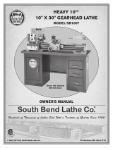
Figure 1. SB1090 37" x 53" Downdraft Table.
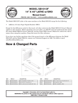
Figure 2. Model SB1090 Inventory.
A B
C
D
E
F
INSTRUCTION SHEET
P.O. Box 2027, Bellingham, WA 98227 U.S.A.
PHONE: (360) 734-1540 • www.southbendlathe.com
Model SB1090
37" x 53" Downdraft Table
Copyright © April, 2020 by South Bend Lathe Co.
WARNING: No portion of this manual may be reproduced without written approval.
#KS21049 Printed in Taiwan
Table Size ................................................. 37" x 53"
Shoulder Table Size ................................... 6" x 53"
Table Height Range ................................... 26"–43"
Dust Port Size ......................................................4"
Load Capacity (Per Suction Board) .......... 40.5 lbs.
Weight ......................................................... 140 lbs.
Specifications
The Model SB1090 37" x 53" Downdraft Table
features heavy-duty steel-frame construction,
removable table boards, an internal V-bottom for
directing air flow, and two 4" dust ports.
Both table shoulders sit 11⁄2" below the center
work table for efficient edge-sanding. Table
height can be adjusted from 26" to 43" tall.
Main Inventory (Figure 2) Qty
A. Table ...............................................................1
B. Suction Boards ...............................................7
C. Shoulder Suction Boards ...............................2
D. Foot Pads ........................................................ 4
E. Lower Support Legs ....................................... 4
F. Upper Support Legs .......................................4
Inventory
Not Shown Qty
• Flange Bolts 5⁄16"-18 x 1⁄2" ............................. 32
• Hex Nuts 1⁄2"-13 .............................................. 4
• Work Stop Nuts .............................................. 8
• Work Stops ..................................................... 8
• Grommets ................................................... 264

-2-
For Models Mfd. Since 04/20
Model SB1090 INSTRUCTIONS
This downdraft table and its
components are very heavy.
Get lifting help to move
heavy items.
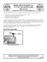
Figure 3. Attaching foot pad to lower support leg.
Figure 6. Dust hose connected to dust port.
x1
Figure 4. Attaching lower support leg to upper leg.
x4
Figure 5. Attaching leg assembly to table.
x4
The procedure that follows describes the general
steps required for assembly.
Assembly
To assemble the downdraft table:
1. Place a piece of cardboard or other protective
material on a flat, level, hard floor, then
place table face-down on it.
2. Attach each foot pad to each lower support
leg using (1) 1⁄2"-13 hex nut (see Figure 3).
3. Attach each lower support leg to each upper
support leg using (4) 5⁄16"-18 x 1⁄2" flange bolts
(see Figure 4).
4. Attach each support leg assembly to each
corner of table using (4) 5⁄16"-18 x 1⁄2" flange
bolts (see Figure 5).
5. Stand table up, and place in desired position.
6. Place suction boards in table and press
grommets in holes, as desired.
7. Connect downdraft table dust port to dust
collection system with a 4" dust hose and
clamp (see Figure 6).
Needed for Setup
Description Qty
• Additional Person for Lifting......................... 1
• Safety Glasses (for each person) ................... 1
• Adjustable Wrench ......................................... 1
• Dust Collection Hose 4" ................................. 1
• Hose Clamp 4" ................................................ 1

For Models Mfd. Since 04/20 Model SB1090
-3-
INSTRUCTIONS
2
1
4
4
6
7
5
3
4
4
6
7
5
3
4
4
6
7
5
3
4
4
6
7
5
3
8
8
11
9
10
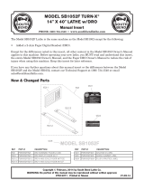
REF PART # DESCRIPTION REF PART # DESCRIPTION
1 PSB1090001 SUCTION BOARD 7 PSB1090007 SUPPORT LEG (LOWER)
2 PSB1090002 TABLE 8 PSB1090008 SHOULDER SUCTION BOARD
3 PSB1090003 FOOT PAD 1/2-13 X 3-1/8 9 PSB1090009 WORK STOP NUT
4 PSB1090004 FLANGE BOLT 5/16-18 X 1/2 10 PSB1090010 WORK STOP
5 PSB1090005 HEX NUT 1/2-13 11 PSB1090011 GROMMET
6 PSB1090006 SUPPORT LEG (UPPER)
Parts Breakdown & List*
* Breakdown is for illustration purposes. Not all
parts may be available for purchase.

-4-
For Models Mfd. Since 04/20
Model SB1090 INSTRUCTIONS
The safety labels provided with your machine are used to make the operator aware of the
machine hazards and ways to prevent injury. The owner of this machine MUST maintain the
original location and readability of these safety labels. If any label is removed or becomes
unreadable, REPLACE that label before using the machine again. Contact South Bend Lathe Co. at
(360) 734-1540 or www.southbendlathe.com to order new labels.
101
102
103
104
105
REF PART # DESCRIPTION REF PART # DESCRIPTION
101 PSB1090101 MODEL NUMBER LABEL 104 PSB1090104 TOUCH-UP PAINT, SB LIGHT BLUE
102 PSB1090102 SOUTH BEND NAMEPLATE 125MM 105 PSB1090105 TOUCH-UP PAINT, SB DARK BLUE
103 PSB1090103 MACHINE ID LABEL
Machine Labels
/