108/228106-803D
R
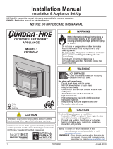
PELLET BURNING APPLIANCE
MODEL NUMBER:
OUTFITTER-I
Installation and service of this appliance should be performed by
qualified personnel. Hearth & Home Technologies recommends
HHT Factory Trained or NFI certified professionals.
Installation Manual
Installation & Appliance Set-Up
INSTALLER: Leave this manual with party responsible for use and operation.
OWNER: Retain this manual for future reference.
NOTICE: DO NOT DISCARD THIS MANUAL
NOTE: To obtain a French translation of this manual,
please contact your dealer or visit www.quadrare.com.
REMARQUE : Pour obtenir une traduction française de
ce manuel, s’il vous plaît contacter votre revendeur ou
visitez www.quadrare.com.
If the information in these instructions is
not followed exactly, a re could result
causing property damage, personal injury,
or death.
WARNING
• Donotstoreorusegasolineorotherammablevapors
and liquids in the vicinity of this or any other appliance.
• Donotoverre-Ifapplianceorchimneyconnector
glows, you are over ring. Over ring will void
your warranty.
• Comply with all minimum clearances to combustibles
asspecied.
Failuretocomplymaycausehousere.
HOT SURFACES!
Glass and other surfaces are hot
during operation AND cool down.
WARNING
Hot glass will cause burns.
• Do not touch glass until it is cooled
• NEVER allow children to touch glass
• Keep children away
• CAREFULLY SUPERVISE children in same room
asreplace.
• Alert children and adults to hazards of
high temperatures
• High temperatures may ignite clothing or other
ammable materials.
• Keep clothing, furniture, draperies and other
ammablematerialsaway.
Check building codes prior to installation.
• Installation MUST comply with local, regional, state
and national codes and regulations.
• Consult local building, re ocials or authorities
having jurisdiction about restrictions, installation
inspection, and permits.
CAUTION
Tested and approved for use with wood pellets ONLY.
Burning of any other fuel will void your warranty.
CAUTION

208/228106-803D
TABLE OF CONTENTS
Safety Alert Key:
• DANGER!Indicatesahazardoussituationwhich,ifnotavoidedwillresultindeathorseriousinjury.
• WARNING!Indicatesahazardoussituationwhich,ifnotavoidedcouldresultindeathorseriousinjury.
• CAUTION!Indicatesahazardoussituationwhich,ifnotavoided,couldresultinminorormoderateinjury.
• NOTICE:Indicatespracticeswhichmaycausedamagetotheapplianceortoproperty.
Quadra-FireisaregisteredtrademarkofHearth&HomeTechnologies.
1 Important Safety Information
A.ApplianceSafetyCertication ...................3
B.ApplianceEmissionsCertication ................3
C.BTU&EciencySpecications..................3
D.GlassSpecications...........................4
E. Electrical Rating (on high) ......................4
F.MobileHomeApproved ........................4
G.Non-CombustibleMaterials .....................4
H.CombustibleMaterials .........................4
I.SleepingRoom ...............................4
J. Stove Composition . . . . . . . . . . . . . . . . . . . . . . . . . . . .4
K.California-Prop65 ............................4
2 Getting Started
A.Design,Installation&LocationConsiderations ......5
B. Thermostat Wall Control Location ................6
C. Tools And Supplies Needed .....................6
D.InspectApplianceandComponents ..............6
E. Removal of Appliance from Pallet ................6
F.InstallChecklist...............................7
3 Dimensions and Clearances
A. Appliance Dimensions .........................8
B. Clearances to Combustibles (UL and ULC) .........9
C. Hearth Pad Requirements (UL and ULC) ..........9
4 Vent Information
A.VentingTerminationMinimumRequirements.......11
B.AvoidingSmokeandOdors ....................12
C. Negative Pressure ...........................13
D. Draft . . . . . . . . . . . . . . . . . . . . . . . . . . . . . . . . . . . . . .13
E.MinimumVacuumRequirements ................13
F. Chimney and Exhaust Connection ...............13
G. Equivalent Feet of Pipe . . . . . . . . . . . . . . . . . . . . . . .14
H. Pipe Selection Chart .........................14
5 Venting Systems
A. Through The Wall............................15
B.Vertical-Interior-TypicalInstallation ............16
C.ThroughTheWall&Vertical-ExternalHorizontal...16
D. Vertical into Existing Class A Chimney............16
E.Interior-RearVent...........................17
F.Masonry ...................................17
G.AlternateMasonry ...........................17
H. Through the Wall ............................18
6 Appliance Set-Up
A.OutsideAirKit ..............................19
B.ThermostatInstallationandOperation ............20
7 Mobile Home Installation .....................21
8 Reference Materials
A.Service&MaintenanceLog ....................22
= Contains updated information

308/228106-803D
Model Outtter-I
Laboratory UL LLC
Report No. MH60687
Type Solid Fuel Room Appliance/Pellet Fuel
Burning Type
Standard
ASTME1509andULCS627Room
Appliance Pellet Fuel Burning type and
(UM)84-HUD,
MobileHomeApproved.
A. Appliance Safety Certication
NOTICE: This installation must conform with local codes.
Intheabsenceoflocalcodesyoumustcomplywiththe
ASTM E1509, ULC S627 and (UM) 84-HUD.
C. BTU & Eciency Specications
This pellet appliance needs periodic inspection and repair
for proper operation. Consult the owner’s manual for further
information.Itisagainstfederalregulationstooperatethis
pellet appliance in a manner inconsistent with operating
instructions in this manual.
EPA Certication
Number: 184-19
EPA Certied
Emissions: 0.7 grams per hour
*LHV Tested Eciency: 79.4%
**HHV Tested Eciency: 74.6%
***EPA BTU Output: 6,800-26,000perhr
****BTU Input: 9,600to33,200perhr
Vent Size: 3” or 4” Type “L” or “PL”
Hopper Capacity: 60lbs.
Fuel Premium Wood Pellets
*WeightedaverageLHV(LowHeatingValue)eciency
using data collected during EPA emissions tests in
accordancewiththerequirementsofCSAB415.1.
**WeightedaverageHHV(HighHeatingValue)eciency
using data collected during EPA emissions tests in
accordancewiththerequirementsofCSAB415.1.
***ArangeofBTUoutputscalculatedusingHHVeciency
and the burn rates from the EPA tests.
**** Based on the maximum feed rate per hour multiplied
byapproximately8600BTU’swhichistheaverageBTU’s
from a pound of pellets.
The Outtter-I is Certied to comply with
2020 particulate emission standards.
Model Outtter-I
Laboratory OMNITestLaboratories,Inc.
Report No. 0061PS095E
Standard ASTME2779andASTME2515
Can be found at:
www.quadrare.com/about-us/epa-certication
B. Appliance Emissions Certication
1 1 Important Safety Information

408/228106-803D
D. Glass Specications
This appliance is equipped with 5mm ceramic glass.
Replaceglassonlywith5mmceramicglass.Pleasecontact
your dealer for replacement glass.
E. Electrical Rating (on high)
115VAC,60Hz,Start2.6Amps,Run.9Amps
F. Mobile Home Approved
• This appliance is approved for mobile home installations
when not installed in a sleeping room and when an
outside combustion air inlet is provided.
• Thestructuralintegrityofthemobilehomeoor,ceiling,
and walls must be maintained.
• The appliance must be properly grounded to the frame
of the mobile home with #8 copper ground wire, and use
onlylisteddouble-wallconnectorpipe.
• OutsideAirKit,part811-0872orOAK-3mustbeinstalled
in a mobile home installation.
• Appliance must be secured to mobile home structure.
G. Non-Combustible Materials
Material which will not ignite and burn, composed of any
combination of the following:
- Steel
- Plaster
- Brick
- Iron
- Concrete
- Tile
- Glass
- Slate
Materials reported as passing ASTM E 136, Standard
Test Method for Behavior of Metals, in a Vertical Tube
Furnace of 750° C.
H. Combustible Materials
Material made of/or surfaced with any of the
following materials:
- Wood
- CompressedPaper
- PlantFibers
- Plastic
- Plywood/OSB
- SheetRock(drywall)
Any material that can ignite and burn:ameproofedornot,
plasteredornon-plastered.
I. Sleeping Room
When installed in a sleeping room it is recommended that
3ft of vertical be installed prior to horizontally exiting the
roomandasmoke/COalarmbeinstalledinthebedroom.
Thesizeoftheroommustbeatleast50ft³per1,000Btu/hr
stove input, if the stove exceeds the room size, outside air
must be installed.
J. Stove Composition
These pellet burning stoves are made of steel, cast iron or
a combination of both with a ceramic viewing glass. These
stoves incorporate a self-feeding system including a fuel
storage hopper and a mechanical feed system which is
controlledbyamicro-processingcontrolboard.Eachmodel
contains a variable speed distribution blower to circulate
room air through the heat exchanger and out to the room
and a combustion blower which forces the exhaust out of
the stove.
K. California - Prop65
This product and the fuels used to operate this product (wood), and the
products of combustion of such fuels, can expose you to chemicals
including carbon black, which is known to the State of California to
cause cancer, and carbon monoxide, which is known to the State of
California to cause birth defects or other reproductive harm. For more
information go to: WWW.P65Warnings.ca.gov
WARNING
NOTE: Hearth & Home Technologies, manufacturer of
this appliance, reserves the right to alter its products,
theirspecicationsand/orpricewithoutnotice.
Improper installation, adjustment, alteration, service or
maintenance can cause injury or property damage.
Forassistanceoradditionalinformation,consultaqualied
installer, service agency or your dealer.
• Installationanduseofanydamagedappliance.
• Modicationoftheappliance.
• InstallationotherthanasinstructedbyHearth&Home
Technologies.
• Installation and/or use of any component part not
approvedbyHearth&HomeTechnologies.
• Operating appliance without fully assembling
all components.
• Operatingappliancewithoutlegsattached(ifsupplied
with appliance).
• DoNOTOverre-Ifapplianceorchimneyconnector
glows,youareoverring.
Anysuchactionthatmaycausearehazard.
Fire Risk
Hearth&HomeTechnologiesdisclaimsany
responsibility for, and the warranty will be
voided by, the following actions:
WARNING
CAUTION
USEOFIMPROPERFUELS,FIRESTARTERSORALTERING
THE STOVE FOR HIGHER HEAT OUTPUT MAY CAUSE
DAMAGETOTHESTOVEANDCOULDRESULTINAHOUSE
FIRE. USE ONLY APPROVED FUELS AND OPERATION
GUIDELINES

508/228106-803D
Recommended
Location
Marginal
Location
Location
Not
Recommended
Recommended
Location
Location NOT
Recommended
Multi-level Roofs
Windward
Leeward
Outside Air Kit Termination Cap
Figure 5.1
A. Design, Installation & Location Considerations
1. Appliance Location
NOTICE: Check building codes prior to installation.
2 2 Getting Started
Since pellet exhaust can contain ash, soot or sparks, you
must consider the location of:
• Windows
• AirIntakes
• Air Conditioner
• Overhang,sots,porchroofs,adjacentwalls
• Landscaping, vegetation
• Horizontal or vertical vent termination
2. Floor Support
Thesupporting oor undertheappliance must beable to
handle the weight of the appliance, fuel load and the weight
of the chimney.
Ensure that your oor will support these weights prior to
installation. Add sucient additional support to meet this
weight requirement prior to installation. The weight of the
appliance is 240 lbs.
• InstallationMUSTcomplywithlocal,regional,stateand
national codes and regulations.
• Consult insurance carrier, local building inspector, re
ocialsorauthoritieshavingjurisdictionoverrestrictions,
installation inspection and permits.
It is a good idea to plan your installation on paper, using
exact measurements for clearances and oor protection,
before actually beginning the installation. Location of the
applianceandchimneywillaectperformance.
Consideration must be given to:
• Safety,convenience,tracow
• Placement of the chimney and chimney connector and to
minimizetheuseofchimneyosets.
• Place the appliance where there will be a clear passage
for a Listed chimney through the ceiling and roof (vertical)
or through exterior wall (horizontal).
• Installingtherequiredoutsideairkitwillaectthelocation
of the vent termination.
When locating vent and venting termination, the ideal
location is to vent above roof line when possible. This
minimizestheaectsofwindloading.
WARNING
Risk of Fire.
Damaged parts could impair safe operation. Do
NOTinstalldamaged,incompleteorsubstitute
components.

608/228106-803D
B. Thermostat Wall Control Location
Thethermostatwallcontrol’slocationwillhavesomeaect
on the appliance’s operation.
• Ifyouneedtorunmorethan25’makesureyouusea
continuous strand of 18 to 22 gauge thermostat wire.
• When located close to the appliance, it may require a
slightly higher temperature setting to keep the rest of the
house comfortable.
• When located in an adjacent room or on a dierent
oor level, you will notice higher temperatures near
the appliance.
C. Tools And Supplies Needed
Tools and building supplies normally required for installation,
unlessinstallingintoanexistingmasonryreplace:
- ReciprocatingSaw
- ChannelLocks
- Hammer
- PhillipsScrewdriver
- TapeMeasure
- PlumbLine
- 1/4”Self-TappingScrews
- FramingMaterial
- Hi-tempCaulkingMaterial
- Gloves
- SafetyGlasses
- FramingSquare
- ElectricDrill&Bits(1/4”)
- Level
Mayalsoneed:
- VentSupportStraps
- VentingPaint
D. Inspect Appliance and Components
• Opentheapplianceandremoveallthepartsandarticles
packedinsidetheComponentPack.Inspectalltheparts
and glass for shipping damage.
• Report to your dealer any parts damaged in shipment.
• All labels have been removed from the glass door.
• Plated surfaces have been wiped clean with a soft cloth,
if applicable.
• Read all the instructions before starting the
installation. Follow these instructions carefully
during the installation to ensure maximum safety
and benet.
• Follow pipe manufacturer instructions for installation
and air clearance requirements.
Risk of Fire!
• Damaged parts could impair safe
operation.
• Do NOT install damaged, incomplete or
substitute components.
WARNING
WARNING
Hearth & Home Technologies disclaims any
responsibility for, and the warranty will be
voided by, the following actions:
• Installationanduseofanydamagedappliance.
• Modicationoftheappliance.
• InstallationotherthanasinstructedbyHearth&Home
Technologies.
• Installation and/or use of any component part not
approvedbyHearth&HomeTechnologies.
• Operating appliance without fully assembling
all components.
• Operatingappliancewithoutlegsattached(ifsupplied
with appliance).
• DoNOTOverre!
Or any such action that may cause a re hazard.
E. Removal of Appliance from Pallet
1. Remove box and 2x4 structural boards being careful not
to damage product
2. Using 3/8 socket or wrench, loosen the (2) retaining bolts
on the back of stove and remove right panel.
3. Using7/16socketorwrench,removepalletmountbolts
and washers.
4. Remove pallet from under stove
5. Assemblesidepanelbackonstove
Retaining Bolts
Pallet mount bolts and washers
Figure 6.1

708/228106-803D
F. Install Checklist
YES IF NO, WHY?
Verified clearance to combustibles.
Appliance is leveled and connector is secured to appliance.
Hearth extension size/height decided.
Outside air kit installed.
Floor protection requirements have been met.
If appliance is connected to a masonry chimney, it should be cleaned and
inspected by a professional. If installed to a factory built metal chimney, the
chimney must be installed according to the manufacturer’s instructions and
clearances.
Appliance Install
Chimney configuration complies with diagrams.
Chimney installed, locked and secured in place with proper clearance.
Chimney meets recommended height requirements (5 feet minimum vertical).
Roof flashing installed and sealed.
Terminations installed and sealed.
Venting/Chimney
Clearances
Verified all clearances meet installation manual requirements.
Mantels and wall projections comply with installation manual requirements.
Floor protection and heart extensions installed per manual requirements.
Appliance Setup
All protective materials removed.
All labels have been removed from the door.
All packaging materials are removed from inside/under appliance.
Manual bag and all of its contents are removed from inside/under the appliance
and given to the party responsible for use and operation.
WARNING! Risk of Fire or Explosion! Failure to install appliance to these instructions can lead to a fire or
explosion.
Hearth & Home Technologies recommends the following:
Photographing the installation and copying this checklist for your file.
That this checklist remain visible at all times on the appliance until the installation is complete.
Electrical
120 VAC unswitched power provided to the appliance.
Check outlet with multi-meter for proper polarity and voltage (115-120 VAC).
Record voltage reading: _____________
ATTENTION INSTALLER:
Follow this Standard Work Checklist
This standard work checklist is to be used by the installer in conjunction with, not instead of, the instructions contained in this installation manual.
Customer:
Date Installed:
Lot/Address:
Location of Appliance:
Installer:
Dealer/Distributor Phone Number:
Serial Number:
Model Name:
__________________________________________________________________________
______________________________________________________________________
_______________________________________________________________________
________________________________________________________________
___________________________________________________________________________
________________________________________________________
______________________________________________________________________
_______________________________________________________________________
Started appliance and verified that all motors and blowers operate as they should.
Checked draft using a Manometer. Record readings: ______________________
Comments: Further description of the issues, who is responsible (Installer/Builder/Other Trades, ets.) and corrective action needed:
Comments communicated to party responsible __________________________ by ______________________ on ____________
(Builder/Gen. Contractor) (Installer) (Date)
Checked vacuum using a Manometer. Record readings: ____________________

808/228106-803D
A. Appliance Dimensions
Figure 8.1-TopView
3-1/2” (89mm)
Figure 8.3-FrontView
21-3/4”
(552mm)
33-3/4”
(858mm)
7-7/8”
(200mm)
11-3/8”
(289mm)
Figure 8.2-SideView
12-7/8”
(326mm)
22-1/8”
(562mm)
3 3 Dimensions and Clearances

908/228106-803D
B. Clearances to Combustibles (UL and ULC) NOTE:
• Illustrations reect typical installations and are FOR
DESIGNPURPOSESONLY.
• Illustrations/diagramsarenotdrawntoscale.
• Actual installation may vary due to individual
design preference.
Straight Back Against Wall Inches Millimeters
ABack Wall to Pellet Pipe 3 76
BSide Wall to Appliance 13 330
Corner Installation
Straight Back Against Wall Inches Millimeters
CWalls to Appliance 376
Horizontal Installation
Straight Back Against Wall Inches Millimeters
DBack wall to Appliance 2 51
BSide wall to Appliance 13 330
Table 9.1
C. Hearth Pad Requirements (UL and ULC)
EMBER PROTECTION: ItisnecessarytoinstallaTypeI
oorprotector.
Floorprotectormustbenon-combustiblematerial,extending
beneath appliance
withaminimumof6
inches(152mm)in
front of glass and 6 inches (152mm) to both sides of the
fuel loading door. Open the door and measure 6 inches
(152mm)fromthesideedgeoftheopeninginthefaceof
the appliance, Figures 10.1 thru 10.4.
USA INSTALLATIONS: A
non-combustibleoorprotection
is recommended extending beneath the ue pipe when
installed with horizontal venting or under the Top Vent
Adapter with vertical installation.
CANADA INSTALLATIONS: A
non-combustible oor
protection extending beneath the ue pipe is required
with horizontal venting or under the Top Vent Adapter with
vertical installation.
D
B
A
Figure 9.1
C
C
Figure 9.2
CAUTION
Hearth and Home Technologies does not recommend adhesive
based vinyl ooring due to thermal expansion. Floating-style
ooring(LVP-luxuryvinylplankorLVT–luxuryvinyltile)canbe
used, but it will reach temperatures up to 110 °F in a room with
ambienttemperatureof70°F.Consultooringspecicationsto
ensure compatibility.
WhenusingLVP/LVTooring,pelletstoveandinsertsrequire
29inchesofalternativeooringin front of the stove or insert
beforeusingLVP/LVT(luxuryvinylplank/tileooring).Whether
the stove or insert sits ush on the oor or is elevated on a
raised hearth, 29 inches of alternative ooring is required in
front of the stove or insert.
Forallotherooring,continuetofollowclearancetocombustible
requirements in the installation manual.

10 08/228106-803D
(from side of appliance)
51mm
635mm
733mm
346mm (from front of appliance)
152mm
Canada
Figure 10.2
34-1/2”
(876mm)
3”
(76mm)
42”
(1067mm)
13-58”
(346mm)
24-7/8”
(632mm)
USA
Figure 10.3
876mm 76mm
1067mm
346mm
632mm
Canada
Figure 10.4
Fire Risk
Comply with all minimum clearances to
combustiblesasspecied.
Failuretocomplymaycausehousere.
WARNING
(from side of appliance)
2”
(51mm)
25”
(635mm)
28-7/8”
(733mm)
13-5/8”
(346mm) (from front of appliance)
6”
(152mm)
USA
Figure 10.1

11 08/228106-803D
A. Venting Termination Minimum Requirements
J or K
X
V
M
I
H
A
V
G
B
V
V
A
B
V
FV
C
B
B
E
L
V
D
V
Electrical
Service
V
N
VN
V
N
N
V
Inside Corner
FIXED
CLOSED
OPEN
OPEN
FIXED
CLOSED
VX
G
G
Termination Cap Air Supply Inlet Gas Meter Restricted Area
O
P
A12 in. Above Finish Grade (the grade surface
mustbeanon-combustiblematerial
B12 in.
48in.noOAK Opendoororwindow:belowortotheside
B12 in. Opendoororwindow:above
C6in. Permanently closed window: above, below
or to the side
D18 in.
36in.noOAK
Vertical clearance to a ventilated sot
located above the terminal within a
horizontaldistanceof2ftfromthecenter-
line of the terminal
E12 in. Clearancetounventilatedsot
F12 in. Clearance to outside corner
G12 in. Clearance to inside corner
H36in. Above gas meter/regulator measured from
horizontalcenter-lineofregulator
I36in.USA
72 in. Canada Clearance to service regulator vent outlet
J12 in.
48in.noOAK
Clearance to non-mechanical air supply
inlet to the building or the combustions air
inlet to any other appliance
K10 ft horizontal
3 ft vertical Clearance to mechanical air supply
L7 ft. Above paved sidewalk, paved driveway
located on public property
M12 in. Under an open veranda, porch, deck or
balcony
NSee Note
below*
Electric service: above, below or to the side
(location must not obstruct or interfere with
access)
O24 in. Adjacent building, fences and protruding
parts of the structure
P12 in. Clearance above roof line for vertical
terminations
All minimum clearances are listed with an Outside Air Kit (OAK) installed, unless otherwise noted in table below.
24 in. Abovegrass,topofplants,woodoranyothercombus-
tible
12 in.
36in.noOAK
Clearance from any forced air intake of other appliance
12 in. Clearance horizontally from combustible wall
15in. Vented directly through a wall, minimum length of
horizontal pipe
6in.horizontal
12 in. vertical
Minimumhorizontalorverticalterminationsmustpro-
trude from wall
*NOTE: Consultlocalbuilding,reocialsorauthorities
having jurisdiction. Local codes or regulations may require
dierentclearances.
NOTICE:
Termination must exhaust above air
inlet elevation.
• It isrecommended that atleast 60inches (1.52m)of
vertical pipe be installed when appliance is vented
directly through a wall. This will create a natural draft,
which will help prevent the possibility of smoke or odor
venting into the home during a power outage.
• It will also keep exhaust from causing a nuisance
or hazard by exposing people or shrubs to
high temperatures.
• The safest and preferred venting method is to extend
the vent vertically through the roof or above the roof.
NOTICE: Do NOT Terminate Vent:
• In anylocationthatwill allowuegasesorsoot from
entering or staining the building.
•
Inanylocationwhichcouldcreateanuisanceorhazard.
• In any enclosed or semi-enclosed area such as a
carport, garage, attic, crawl space, under a sun deck or
porch, narrow walkway.
• Closely fenced area, or any location that can build up
a concentration of fumes such as a stairwell, covered
breezeway, etc.
4 4 Vent Information

12 08/228106-803D
B. Avoiding Smoke and Odors
Negative Pressure, Shut-Down and Electrical
Power Failure
To reduce the probability of back-drafting or burn-back
in the pellet appliance during power failure or shut down
conditions, it must be able to draft naturally without exhaust
blower operation.
Negative pressure in the house will resist this natural draft if
not accounted for in the pellet appliance installation.
Heat rises in the house and leaks out at upper levels. This
airmustbereplacedwithcoldairfromoutdoorswhichows
into lower levels of the house.
Vents and chimneys into basements and lower levels of the
house can become the conduit for air supply and reverse
under these conditions.
Outside Air
An outside air kit is recommended in all installations. The
OutsideAirKitmustbeorderedseparately.
Per national building codes, consideration must be given to
combustion air supply to all combustion appliances. Failure
to supply adequate combustion air for all appliance demands
mayleadtoback-draftingofthoseandotherappliances.
When the appliance is roof vented (strongly recommended):
The air intake is best located on the exterior wall
oriented towards the prevailing wind direction during
the heating season.
Whentheapplianceisside-wallvented:
The air intake is best located on the same exterior wall
as the exhaust vent outlet and located lower on the wall
than the exhaust vent outlet.
The outside air supply kit can supply most of the demands
of the pellet appliance, but consideration must be given to
the total house demand.
House demand may consume the air needed for the
appliance.Itmaybenecessarytoaddadditionalventilation
to the space in which the pellet appliance is located.
Consult with your local HVAC professional to determine the
ventilation demands for your house.
Hearth&HomeTechnologiesassumesnoresponsibility
for, not does the warranty extend to, smoke damage
caused by reverse drafting of pellet appliances under
shut down or power failure conditions.
Vent Congurations
When installing a pellet appliance with a horizontal vent
conguration the frequency of power outages should
be considered:
• Power outages during operation will cause the appliance
toimmediatelyturnoandmaycreateconditionswhere
smokewillbackdraftintothehouse.Inordertoreduce
the likelihood of smoke back drafting into the house
during a power outage, Hearth and Home Technologies
strongly suggests:
- Installing the pellet venting with a minimum vertical
runof5feet(1.52m).
- Installing the outside air kit at least 4 feet (1.22m)
below the vent termination.
To prevent soot damage to exterior walls of the house and
topreventre-entryofsootorashintothehouse:
• Maintainspeciedclearancestowindows,doorsandair
inlets, including air conditioners.
• Ventsshouldnotbeplacedbelowventilatedsots.Run
the vent above the roof.
• Avoid venting into alcove locations.
• Vents should not terminate under overhangs, decks or
onto covered porches.
• Maintainminimumclearanceof12inches(305mm)from
theventterminationtotheexteriorwall.Ifyouseedeposits
developing on the wall, you may need to extend this
distance to accommodate your installation conditions.
• DONOTCONNECTTHISApplianceTOACHIMNEY
FLUESERVICINGANOTHERAPPLIANCE.
• DO NOT CONNECT TO ANY AIR DISTRIBUTION
DUCTORSYSTEM.
CAUTION

13 08/228106-803D
C. Negative Pressure
Negative pressure results from the imbalance of air available
fortheappliancetooperateproperly.Itcanbestrongestin
lower levels of the house.
Causes include:
• Exhaust fans (kitchen, bath, etc.)
• Range hoods
• Combustion air requirements for furnaces, water
appliances and other combustion appliances
• Clothes dryers
• Locationofreturn-airventstofurnaceorairconditioning
• ImbalancesoftheHVACairhandlingsystem
• Upper level air leaks such as:
- Recessedlighting
- Attichatch
- Ductleaks
To minimize the eects of negative air pressure:
• Installtheoutsideairkitwiththeintakefacingprevailing
winds during the heating season
• Ensure adequate outdoor air for all combustion
appliances and exhaust equipment
• Ensure furnace and air conditioning return vents are not
located in the immediate vicinity of the appliance
• Avoid installing the appliance near doors, walkways or
small isolated spaces
• Recessed lighting should be a “sealed can” design
• Attic hatches weather stripped or sealed
• Attic mounted duct work and air handler joints and seams
taped or sealed
NOTICE: Hearth & Home Technologies assumes no
responsibility for the improper performance of the
chimney system caused by:
• Inadequatedraftduetoenvironmentalconditions
• Down drafts
• Tight sealing construction of the structure
• Mechanicalexhaustingdevices
D. Draft
Draftisthepressuredierenceneededtoventanappliance
successfully. When an appliance is drafting successfully, all
combustion byproducts are exiting the home through the
chimney.
Installthroughthewarmairspaceenclosedbythebuilding
envelope. This helps to produce more draft, especially
duringlightinganddie-downofthere.
Considerations for successful draft include:
• Preventing negative pressure
• Location of appliance and chimney
NOTE: Follow venting manufacturers recommendations
for sealing pipe joints.
E. Minimum Vacuum Requirements
.075inchesW.C.
F. Chimney and Exhaust Connection
1. Chimney & Connector: Use 3 or 4 inch (76-102mm)
diameter type “L” or “PL” venting system. It can be
vented vertically or horizontally.
2. Mobile Home: ApprovedforallListedpelletvent.Ifusing
the3inch(76mm)verticalTopVentAdapterKitorthe3
to6inch(76-152mm)TopVentOsetAdapter,useListed
doublewallueconnector.AQuadra-FireOutsideAirKit
must be used with manufactured home installations.
3. Residential: The 3 inch (76mm) vertical Top Vent
Adapter Kit and the 3 to 6 inch (76-152mm) Top Vent
OsetAdapter are tested to use 24 gauge single wall
ue connector or Listed double wall ue connector to
Class A Listed metal chimneys, or masonry chimneys
meeting International Residential Code standards for
solid fuel appliances.
4. INSTALL VENT AT CLEARANCES SPECIFIED BY
THE VENT MANUFACTURER.
5. Seal exhaust venting system to the appliance with High
Temp 500ºF RTV silicone sealant. Secure the venting
system to the appliance with at least (3) screws. All pellet
vent pipe must be secured together either by means
provided by the pipe manufacturer or by (3) screws at
each joint.
6. DONOTINSTALLAFLUEDAMPERINTHEEXHAUST
VENTINGSYSTEMOFTHISAppliance.
7. DO NOT CONNECT THISAppliance TOA CHIMNEY
FLUESERVINGANOTHERAPPLIANCE.
Risk of Asphyxiation!
Negative pressure can cause spillage of combustion
fumes and soot.
WARNING

14 08/228106-803D
G. Equivalent Feet of Pipe
The table below can help you calculate the equivalent feet
of pipe which is a method used to determine pellet vent
size (Figure 14.1).
NOTE:Thisisagenericexampleandisnotintendedtorepresentanyspecicfueltype.
Figure 14.2
3 in. or 4 in. (76mm or
102mm) Diameter Pipe
3 in. or 4 in. (76mm or
102mm) Diameter Pipe
Equivalent Pipe
Length In Feet
Equivalent Pipe
Length In Feet
ALTITUDE IN THOUSANDS OF FEETALTITUDE IN THOUSANDS OF FEET
0
20
30
1 2 3 4 5 6 7 8 9 10
4 in. (102mm) Diameter Pipe Only4 in. (102mm) Diameter Pipe Only
10
Example 1Example 1
Example 2
Example 2
• Example 1: If the equivalent length of pipe is 23 feet
(7m) with altitude of 8,000 feet (2438m) you must use 4
inch (102mm) diameter type “L” or “PL” vent.
• Example 2: If the equivalent length of pipe is 12 feet
(3.7m)withaltitudeof6,000feet(1829m)youmayuse3
or4inch(76to102mm)diametertype“L”or“PL”vent.
H. Pipe Selection Chart
The chart will help you in determining proper venting size
according to the equivalent feet of pipe calculated previously
and the altitude above sea level of this installation (Figure
14.2).
1. Locate the calculated equivalent feet of pipe on the
vertical left side of the chart.
2. Movetotherighthorizontallyonthechartuntilyoureach
your altitude above sea level.
3. If you fall below the diagonal line, 3 or 4 inch (76 to
102mm) pipe may be used.
4. Ifitisanywhereabovethediagonalline,a4inch(102mm)
diameter pipe is required.
Pellet
Venting
Component
# of
Elbows
Feet of
Pipe
Multiplied
By
Equivalent
Feet
Components
Equivalent
Feet
90° Elbow
or Tee 3X 5 15
45° Elbow X3
Horizontal
Pipe 7X1 7
Vertical
Pipe 2X 0.5 1
Total Equivalent Feet 23
2 ft.
2 ft.
3 ft.
2 ft.
Example of 3 Elbow-Rear Vent Termination Calculation
Figure 14.1 Table 14.1
NOTICE:
• A 90° elbow is 5 times as restrictive to the ow of
exhaust gases under positive pressure as 1 foot
(305mm)ofhorizontalpipe.
• A foot of horizontal pipe is twice as restrictive as a foot
of vertical pipe.
Vent surfaces get HOT, can cause burns
if touched. Non-combustible shielding or
guards may be required.
CAUTION
Risk of Fire!
• Only LISTED venting components may
be used.
• NO OTHER vent components may
be used.
• Substitute or damaged vent components
may impair safe operation.
WARNING Risk of Injury or Property Damage.
• Improper installation, adjustment,
alteration, service or maintenance can
cause injury or property damage.
• Refer to the owner’s information manual
provided with this appliance.
• For assistance or additional information
consultaqualiedinstaller,serviceagency
or your dealer.
WARNING

15 08/228106-803D
A. Through The Wall
Horizontalterminationcapmustbeaminimumof6
inches.(152mm)fromthewall.Approvedformobilehome
installations.Mustuse3or4inch(76-102mm)“L”or“PL”
listed pellet venting or Listed double wall pipe and an
authorizedOutsideAirKitinmobilehomes.
Wall
Thimble
Illustration shows venting going in both directions.
Choose which one is best for your installation.
3 in.
(76mm)
Minimum
3 in.
(76mm)
Minimum
6 in (152mm) Minimum
6 in
(152mm)
Minimum
Figure 15.2-45Degree
NOTE: In Canada, where passage through a wall or
partition of combustible construction is desired, the
installation shall conform to CAN/CSA-B365
Figure 15.1-StraightOut
6”
(152mm)
Minimum
Non-combustible Hearth Pad
Wall
Thimble Horizontal
Termination
Cap
2”
(51mm)
Minimum
6”
(152mm)
Minimum
from glass
NOTICE: Please note that while the minimum clearance
fortheterminationcapis6inches(152mm)thereisthe
possibilityofsoot build-uparoundthe terminationarea.
Ifthisoccurswesuggesttomovetheterminationfurther
away from the house to prevent it.
5 5 Venting Systems
We strongly recommend that you DO NOT
DOWNWARDVENT.
The following may occur:
• The appliance will not vent properly
• Smoke spillage in the house
• Excessive sooting
CAUTION

16 08/228106-803D
NOTICE: These are guidelines for successful venting
of your pellet appliance. The more vertical rise you can
obtain in your system, the better it will perform. Horizontal
vent runs can accumulate ash and will need to be cleaned
more often. Try to keep them as short as possible.
We strongly recommend a minimum of 60 inches (1.5m)
vertical, however above the eave is preferred.
Both installations are approved for mobile home installations.
Mustuse3or4inch(76to102mm)“L”or“PL”Listedpellet
ventingorListeddoublewallpipeandauthorizedOutside
Air Kit in mobile homes. Single wall pipe is approved for
residential installations only.
Air Clearance to Pipe:
This appliance was tested with standard 3 inch (76mm)
Listed pellet vent.
Pellet pipe manufacturers Listed reduced clearance pipe
may be use for reduce clearance from 3 inch (76mm) air
clearance to no less than 1 inch (25mm) air clearance to
combustibles for approved Listed pellet pipe.
Follow pipe manufactures listed air clearances to
combustibles and installation instructions for all
reduced air clearances installations.
D. Vertical into Existing Class A Chimney
C. Through The Wall & Vertical - External -
Horizontal
B. Vertical - Interior - Typical Installation
Firestop
Flashing
Rain Cap
6 in.
(152mm)
Min.
Non-combustible Hearth Pad
follow pipe manufacture
listed clearance
12 in.
(305mm)
Minimum
Clean-out T
PREFERRED METHOD #1
Figure 16.1
Non-combustible Hearth Pad
Clean-out Cover
Tee
Wall Thimble
Support
Bracket
Every 60 in.
(1.5 m)
12 in.
(305mm)
Minimum
Rain Cap
Flashing
2 in. (5.08 mm) Minimum
6 in. (152 mm)
Minimum
PREFERRED METHOD #2
Figure 16.2
Firestop
Flashing
Rain Cap
Non-combustible Hearth Pad
Follow vent manufacturer’s
clearances for reduced clearances
12 in. (305mm) Minimum
Ceiling Support
6 in. (152mm) Flue
Connector
6 in. (152mm) Class A
Chimney Connector
Adapter
6 in.
(152mm)
Min. follow pipe manufacture
listed clearance
Clean-out T
Figure 16.3

17 08/228106-803D
G. Alternate Masonry
F. Masonry
Fire Risk
InspectionofChimney:
• Masonrychimneymustbeingoodcondition.
• MeetsminimumstandardofNFPA 211
• Factory-built chimney must be minimum 6
inch(152mm)UL103 HT.
WARNING Improper installation, adjustment, alteration, service
or maintenance can cause injury or property damage.
Refer to the owner’s information manual provided with
this appliance. For assistance or additional information
consultaqualiedinstaller,serviceagencyoryourdealer.
WARNING
Non-combustible Hearth Pad
Airtight
Clean-Out Door
Clean-Out
Sheathing
3 in. (76mm) Minimum
1 in. (25mm) Clearance
Flashing
Fireclay flue
Liner with Airspace
Concrete Cap
1 in. (25mm) Clearance
with Firestop
6 in. (152mm)
Minimum
Figure 17.3
E. Interior - Rear Vent
Figure 17.1
Non-combustible Hearth Pad
Wall Thimble
12 in
[305 mm]
Minimum
6 in
[152mm]
Min
6 in
[152mm]
Min
60 in
[1524 mm]
Recommended
Figure 17.2
Non-combustible Hearth Pad
Wall Thimble
12 in
[305 mm]
Minimum
2 in [51mm] min
6 in
[152mm]
Min
Clean-out Tee
60 in
[1524 mm]
Recommended
Non-combustible Hearth Pad
Airtight Clean-out Door
Sheathing
2 in. (5.08mm) Minimum
Flashing
6 in.
(152mm)
Minimum
Fireclay Flue Liner
with Airspace
Concrete Cap
Figure 17.4

18 08/228106-803D
H. Through The Wall
Horizontal termination cap must be a minimum of 6
inches.(152mm)fromthewall.Approvedformobilehome
installations.Mustuse3or4inch(76-102mm)“L”or“PL”
listed pellet venting or Listed double wall pipe and an
authorizedOutsideAirKitinmobilehomes.
NOTE: In Canada, where passage through a wall or
partition of combustible construction is desired, the
installation shall conform to CAN/CSA-B365
NOTICE: Please note that while the minimum clearance
fortheterminationcapis6inches(152mm)thereisthe
possiblyofsootbuild-uparoundtheterminationarea.If
this occurs we suggest to move the termination further
away from the house to prevent it. The suggested
minimum is 12 inches.
Straight Out
45 Degrees
DO NOT DOWNWARD VENT.
The following will occur:
• The appliance will not vent properly
• Smoke spillage in the house
• Excessive sooting
WARNING
6 in.
(152mm)
Minimum
Non-combustible Hearth Pad
Wall
Thimble
Horizontal
Termination
Cap
2 in.
(50.8mm)
Minimum
6 in.
(152mm)
Minimum
From Glass
Figure 18.1
Wall
Thimble
Illustration shows venting going in both directions.
Choose which one is best for your installation.
3 in.
(76mm)
Minimum
3 in.
(76mm)
Minimum
6 in (152mm) Minimum
6 in
(152mm)
Minimum
Figure 18.2

19 08/228106-803D
6 6 Appliance Set-Up
Never draw outside combustion air from:
• Wall,oororceilingcavity
• Enclosed space such as an attic or garage
CAUTION
1. Measure distance from oor to air vent opening in
appliance and mark location on wall.
2. Use a saw to cut opening in wall:
- Cuta2-1/2to3inchopeningoninsidewallanda3to
3-1/2inchopeningonoutsideofhouse.
3. Usehoseclamptosecureexpipetocollarassembly.
4. Slidetrimringoverexpipeandrunpipethroughwall.
5. Attachexpipetooutsideterminationcapwithsecond
hose clamp.
6. Secureterminationcaptooutsidesurface.
7. Secure trim ring to interior wall.
A. Outside Air Kit
Kit811-0872usesa2inchexhose(whichisincludedin
the kit) and uses hose clamps to secure the hose.
Parts Included in 2 inch Kit 811-0872:
1pieceof2inchx3ft.exhose,2hoseclamps,1collar
assembly, 1 termination cap assembly, trim ring, 1 intake air
channel, fasteners.
Tools Needed:
Phillips Head screw driver; wire cutters; and hole saw or
jig saw.
Figure 19.1
RETAINING
BOLTS
KNOCK OUT
AIR INLET TUBE
HOSE CLAMP
FLEX PIPE
HOSE CLAMP
TRIM RING
TERMINATION CAP

20 08/228106-803D
Figure 20.2
B. Thermostat Installation and Operation
The kit comes with a programmable wall thermostat and
25’ of thermostat wire. If you need to run more than 25’
make sure you use a continuous strand of 18 to 22 gauge
thermostat wire. For optimum performance your thermostat
should be:
• Mountedonaninsidewall,approximately5’abovethe
oor
• Do not locate where there is poor air circulation such as in
a corner, alcove, behind doors, bookcase or other objects
• Located away from drafts, direct sunlight, above a lamp,
television, radiator, a wall next to a window, or direct heat
from the appliance
• Avoid damp environments as this can lead to corrosion
that may shorten thermostat life
• If painting or construction work around, cover the
thermostat completely or wait until work is complete before
installation.
1. Connect your thermostat wire to the W and R terminals
(Figure 20.1).
Figure 20.1
WR
WR
Appliance
NOTE: Ensure bare wire ends are held ALL the way into
the terminal block while the screws are being tightened.
There is a 4 screw terminal block located on the back lower
left corner of the appliance directly above the power cord
inlet. The center 2 screws are for the thermostat wires.
Page is loading ...
Page is loading ...
Page is loading ...
/