SMARC-sXEL - User Guide Rev. 1.4
www.kontron.com // 3
SMARC
-SXEL - USER GUIDE
Disclaimer
Kontron would like to point out that the information contained in this user guide may be subject to alteration,
particularly as a result of the constant upgrading of Kontron products. This document does not entail any guarantee on
the part of Kontron with respect to technical processes described in the user guide or any product characteristics set
out in the user guide. Kontron assumes no responsibility or liability for the use of the described product(s), conveys no
license or title under any patent, copyright or mask work rights to these products and makes no representations or
warranties that these products are free from patent, copyright or mask work right infringement unless otherwise
specified. Applications that are described in this user guide are for illustration purposes only. Kontron makes no
representation or warranty that such application will be suitable for the specified use without further testing or
modification. Kontron expressly informs the user that this user guide only contains a general description of processes
and instructions which may not be applicable in every individual case. In cases of doubt, please contact Kontron.
This user guide is protected by copyright. All rights are reserved by Kontron. No part of this document may be
reproduced, transmitted, transcribed, stored in a retrieval system, or translated into any language or computer
language, in any form or by any means (electronic, mechanical, photocopying, recording, or otherwise), without the
express written permission of Kontron. Kontron points out that the information contained in this user guide is
constantly being updated in line with the technical alterations and improvements made by Kontron to the products and
thus this user guide only reflects the technical status of the products by Kontron at the time of publishing.
Brand and product names are trademarks or registered trademarks of their respective owners.
©2021 by Kontron S&T AG
Kontron Europe GmbH
Gutenbergstr. 2
85737 Ismaning, Germany
www.kontron.com

SMARC-sXEL - User Guide Rev. 1.4
www.kontron.com // 4
Intended Use
THIS DEVICE AND ASSOCIATED SOFTWARE ARE NOT DESIGNED, MANUFACTURED OR INTENDED FOR USE OR RESALE
FOR THE OPERATION OF NUCLEAR FACILITIES, THE NAVIGATION, CONTROL OR COMMUNICATION SYSTEMS FOR
AIRCRAFT OR OTHER TRANSPORTATION, AIR TRAFFIC CONTROL, LIFE SUPPORT OR LIFE SUSTAINING APPLICATIONS,
WEAPONS SYSTEMS, OR ANY OTHER APPLICATION IN A HAZARDOUS ENVIRONMENT, OR REQUIRING FAIL-SAFE
PERFORMANCE, OR IN WHICH THE FAILURE OF PRODUCTS COULD LEAD DIRECTLY TO DEATH, PERSONAL INJURY, OR
SEVERE PHYSICAL OR ENVIRONMENTAL DAMAGE (COLLECTIVELY, "HIGH RISK APPLICATIONS").
You understand and agree that your use of Kontron devices as a component in High Risk Applications is entirely at
your risk. To minimize the risks associated with your products and applications, you should provide adequate design
and operating safeguards. You are solely responsible for compliance with all legal, regulatory, safety, and security
related requirements concerning your products. You are responsible to ensure that your systems (and any Kontron
hardware or software components incorporated in your systems) meet all applicable requirements. Unless
otherwise stated in the product documentation, the Kontron device is not provided with error-tolerance capabilities
and cannot therefore be deemed as being engineered, manufactured or setup to be compliant for implementation or
for resale as device in High Risk Applications. All application and safety related information in this document
(including application descriptions, suggested safety measures, suggested Kontron products, and other materials) is
provided for reference only.
You find the most recent version of the “General Safety Instructions“ online in the download
area of this product.
This product is not suited for storage or operation in corrosive environments, in particular
under exposure to sulfur and chlorine and their compounds. For information on how to
harden electronics and mechanics against these stress conditions, contact Kontron Support.

SMARC-sXEL - User Guide Rev. 1.4
www.kontron.com // 5
Revision History
Revision Brief Description of Changes Date of Issue Author/
Editor
1.0 Initial version 2021-Sept-17 CW
1.1 Updates to Chapters 8.2: Watch Dog, 8.3.1: Suspend States, 8.3.3: Power
Management Signals
2021-Oct-04 CW
1.2 Block Diagram DDI2 is HDMI, Table 12 DDI2 is HDMI only and restricted to
HDMI 1.4.
2022-Sept-19 CW
1.3 Removed AC Coupled off Module for pins (92, 93, 95, 96, 97, 99, 101, 102) 2023-Sept-14 CW
1.4 Updated the Eth PHY in Tabel 1 to 1 GbE and rephrased the text in Chapter
6.8 Ethernet.
2023-Oct-04 CW
Terms and Conditions
Kontron warrants products in accordance with defined regional warranty periods. For more information about
warranty compliance and conformity, and the warranty period in your region, visit https://www.kontron.com/terms-
and-conditions.
Kontron sells products worldwide and declares regional General Terms & Conditions of Sale, and Purchase Order Terms
& Conditions. Visit https://www.kontron.com/terms-and-conditions.
For contact information, refer to the corporate offices contact information on the last page of this user guide or visit
our website CONTACT US.
Customer Support
Find Kontron contacts by visiting: https://www.kontron.com/en/support-and-services.
Customer Service
As a trusted technology innovator and global solutions provider, Kontron extends its embedded market strengths into
a services portfolio allowing companies to break the barriers of traditional product lifecycles. Proven product
expertise coupled with collaborative and highly-experienced support enables Kontron to provide exceptional peace of
mind to build and maintain successful products.
For more details on Kontron’s service offerings such as: enhanced repair services, extended warranty, Kontron
training academy, and more visit https://www.kontron.com/en/support-and-services.
Customer Comments
If you have any difficulties using this user guide, discover an error, or just want to provide some feedback, contact
Kontron support. Detail any errors you find. We will correct the errors or problems as soon as possible and post the
revised user guide on our website.

SMARC-sXEL - User Guide Rev. 1.4
www.kontron.com // 6
Symbols
The following symbols may be used in this user guide
DANGER indicates a hazardous situation which, if not avoided,
will result in death or serious injury.
WARNING indicates a hazardous situation which, if not avoided,
could result in death or serious injury.
NOTICE indicates a property damage message.
CAUTION indicates a hazardous situation which, if not avoided,
may result in minor or moderate injury.
Electric Shock!
This symbol and title warn of hazards due to electrical shocks (> 60
V) when touching
products or parts of products. Failure to observe the precautions indicated and/or prescribed
by the law may endanger your life/health and/or result in damage to your material.
ESD Sensitive Device!
This symbol and title informs
that the electronic boards and their components are sensitive
to static electricity. Care must therefore be taken during all handling operations and
inspections of this product in order to ensure product integrity at all times.
HOT Surface!
Do NOT touch! Allow to cool before servicing.
Laser!
This symbol informs of the risk of exposure to laser beam and light emitting devices (LEDs)
from an electrical device. Eye protection per manufacturer notice shall review before
servicing.
This symbol indicates general information about the product and the user guide.
This symbol also indicates detail information about the specific product configuration.
This symbol precedes helpful hints and tips for daily use.

SMARC-sXEL – User Guide Rev. 1.4
www.kontron.com // 7
For Your Safety
Your new Kontron product was developed and tested carefully to provide all features necessary to ensure its
compliance with electrical safety requirements. It was also designed for a long fault-free life. However, the life
expectancy of your product can be drastically reduced by improper treatment during unpacking and installation.
Therefore, in the interest of your own safety and of the correct operation of your new Kontron product, you are
requested to conform with the following guidelines.
High Voltage Safety Instructions
As a precaution and in case of danger, the power connector must be easily accessible. The power connector is the
product’s main disconnect device.
Warning
All operations on this product must be carried out by sufficiently skilled personnel only.
Electric Shock!
Before installing a non hot-swappable Kontron product into a system always ensure that
your mains power is switched off. This also applies to the installation of piggybacks. Serious
electrical shock hazards can exist during all installation, repair, and maintenance operations
on this product. Therefore, always unplug the power cable and any other cables which
provide external voltages before performing any work on this product.
Earth ground connection to vehicle’s chassis or a central grounding point shall remain
connected. The earth ground cable shall be the last cable to be disconnected or the first
cable to be connected when performing installation or removal procedures on this product.
Special Handling and Unpacking Instruction
ESD Sensitive Device!
Electronic boards and their components are sensitive to static electricity. Therefore, care
must be taken during all handling operations and inspections of this product, in order to
ensure product integrity at all times.
Handling and operation of the product is permitted only for trained personnel within a work
place that is access controlled. Follow the “General Safety Instructions” supplied with the
system.
Do not handle this product out of its protective enclosure while it is not used for operational purposes unless it is
otherwise protected.
Whenever possible, unpack or pack this product only at EOS/ESD safe work stations. Where a safe work station is not
guaranteed, it is important for the user to be electrically discharged before touching the product with his/her hands
or tools. This is most easily done by touching a metal part of your system housing.
It is particularly important to observe standard anti-static precautions when changing piggybacks, ROM devices,
jumper settings etc. If the product contains batteries for RTC or memory backup, ensure that the product is not placed
on conductive surfaces, including anti-static plastics or sponges. They can cause short circuits and damage the
batteries or conductive circuits on the product.

SMARC-sXEL - User Guide Rev. 1.4
www.kontron.com // 8
Lithium Battery Precautions
If your product is equipped with a lithium battery, take the following precautions when replacing the battery.
CAUTION: Risk of Explosion if the lithium battery is replaced by an incorrect type. Dispose of
used lithium batteries according to the Instructions.
ATTENTION: Risque d'explosion si la pile au lithium est remplacée par une pile de type
incorrect. Éliminez les piles au lithium usagées conformément aux instructions.
General Instructions on Usage
In order to maintain Kontron’s product warranty, this product must not be altered or modified in any way. Changes or
modifications to the product, that are not explicitly approved by Kontron and described in this user guide or received
from Kontron Support as a special handling instruction, will void your warranty.
This product should only be installed in or connected to systems that fulfill all necessary technical and specific
environmental requirements. This also applies to the operational temperature range of the specific board version
that must not be exceeded. If batteries are present, their temperature restrictions must be taken into account.
In performing all necessary installation and application operations, only follow the instructions supplied by the
present user guide.
Keep all the original packaging material for future storage or warranty shipments. If it is necessary to store or ship
the product, then re-pack it in the same manner as it was delivered.
Special care is necessary when handling or unpacking the product. See Special Handling and Unpacking Instruction.
Quality and Environmental Management
Kontron aims to deliver reliable high-end products designed and built for quality, and aims to complying with
environmental laws, regulations, and other environmentally oriented requirements. For more information regarding
Kontron’s quality and environmental responsibilities, visit http://www.kontron.com/about-kontron/corporate-
responsibility/quality-management.
Disposal and Recycling
Kontron’s products are manufactured to satisfy environmental protection requirements where possible. Many of the
components used are capable of being recycled. Final disposal of this product after its service life must be
accomplished in accordance with applicable country, state, or local laws or regulations.
WEEE Compliance
The Waste Electrical and Electronic Equipment (WEEE) Directive aims to:
Reduce waste arising from electrical and electronic equipment (EEE)
Make producers of EEE responsible for the environmental impact of their products, especially when the product
become waste
Encourage separate collection and subsequent treatment, reuse, recovery, recycling and sound environmental
disposal of EEE
Improve the environmental performance of all those involved during the lifecycle of EEE
Environmental protection is a high priority with Kontron.
Kontron follows the WEEE directive

SMARC-sXEL - User Guide Rev. 1.4
www.kontron.com // 9
Table of Contents
Symbols ................................................................................................................................................................................................................. 6
For Your Safety ................................................................................................................................................................................................... 7
High Voltage Safety Instructions .................................................................................................................................................................. 7
Special Handling and Unpacking Instruction ............................................................................................................................................ 7
Lithium Battery Precautions .......................................................................................................................................................................... 8
General Instructions on Usage ..................................................................................................................................................................... 8
Quality and Environmental Management ................................................................................................................................................ 8
Disposal and Recycling .................................................................................................................................................................................... 8
WEEE Compliance.............................................................................................................................................................................................. 8
Table of Contents............................................................................................................................................................................................... 9
List of Tables ..................................................................................................................................................................................................... 10
List of Figures ..................................................................................................................................................................................................... 11
1/ Introduction ......................................................................................................................................................................................... 13
2/ General Safety Instructions ........................................................................................................................................................... 14
Electrostatic Discharge (ESD) ............................................................................................................................................................... 15
2.1.1. Grounding Methods ............................................................................................................................................................................... 15
3/ Description ........................................................................................................................................................................................... 16
SMARC™ Modules .................................................................................................................................................................................... 16
SMARC-sXEL Module .............................................................................................................................................................................. 16
Variants ........................................................................................................................................................................................................ 17
4/ System Specification ........................................................................................................................................................................ 18
Functional Block Diagram ...................................................................................................................................................................... 18
Top Side Features ..................................................................................................................................................................................... 19
Rear Side Features ................................................................................................................................................................................... 19
Component Main Data Specification ................................................................................................................................................ 20
Mechanical Specification ....................................................................................................................................................................... 21
4.5.1. Mechanical Drawings ........................................................................................................................................................................... 21
Thermal Management Specification ................................................................................................................................................ 23
4.6.1. Heatspreader ......................................................................................................................................................................................... 23
Environmental Specification ................................................................................................................................................................ 25
Compliance ................................................................................................................................................................................................ 26
4.8.1. MTBF ......................................................................................................................................................................................................... 27
Power Specification ................................................................................................................................................................................ 28
5/ Module and Connectors .................................................................................................................................................................. 29
Connectors Location ............................................................................................................................................................................... 29
SMARC Connector .................................................................................................................................................................................... 29
3-pin Fan Connector ............................................................................................................................................................................... 29
6/ Features and Interfaces ................................................................................................................................................................. 30
Processor Support ................................................................................................................................................................................... 30
System Memory Support ....................................................................................................................................................................... 31
Graphics (LVDS, eDP, DP++, HDMI) ..................................................................................................................................................... 31
HD Audio Interfaces ................................................................................................................................................................................ 32
HSIO Overview .......................................................................................................................................................................................... 32
USB ............................................................................................................................................................................................................... 32
6.6.1. USB 2.0 Client Mode ............................................................................................................................................................................. 33
PCIe 3.0 ........................................................................................................................................................................................................ 33
Ethernet ...................................................................................................................................................................................................... 33

SMARC-sXEL - User Guide Rev. 1.4
www.kontron.com // 10
6.8.1. SGMII via SERDES (option) ................................................................................................................................................................. 34
6.8.2. Link and Activity LEDs ........................................................................................................................................................................ 34
SATA 3.0 ...................................................................................................................................................................................................... 34
CAN Bus Interfaces ............................................................................................................................................................................... 35
Eeep ............................................................................................................................................................................................................. 35
eMMC Flash Memory (option) ........................................................................................................................................................... 35
I2C Bus Support ...................................................................................................................................................................................... 35
Kontron CPLD .......................................................................................................................................................................................... 35
RTC .............................................................................................................................................................................................................. 36
SDIO ............................................................................................................................................................................................................ 36
SPI Interfaces .......................................................................................................................................................................................... 37
6.17.1. SPI Boot Flash Chip ............................................................................................................................................................................. 37
TPM 2.0 ..................................................................................................................................................................................................... 37
UART Interfaces ..................................................................................................................................................................................... 38
7/ Pin Definitions .................................................................................................................................................................................... 39
Smart Connector ....................................................................................................................................................................................... 39
7.1.1. Pinout of SMARC Connector (Top Side) .......................................................................................................................................... 40
7.1.2. Pinout of SMARC Connector (Bottom Side) ................................................................................................................................... 51
8/ Configuration ...................................................................................................................................................................................... 66
Boot Select ................................................................................................................................................................................................. 66
8.1.1. Booting the SPI Flash ........................................................................................................................................................................... 66
Watch Dog ................................................................................................................................................................................................. 67
8.2.1. Watchdog Timer Signal ...................................................................................................................................................................... 67
Power Management ............................................................................................................................................................................... 67
8.3.1. Suspend States...................................................................................................................................................................................... 67
8.3.2. Power Button (POWER_BTN#) ....................................................................................................................................................... 68
8.3.3. Power Management Signals ............................................................................................................................................................ 68
9/ uEFI BIOS .............................................................................................................................................................................................. 69
Starting the uEFI BIOS ............................................................................................................................................................................. 69
Navigating the uEFI BIOS ....................................................................................................................................................................... 69
Setup Menus ............................................................................................................................................................................................. 70
Main Setup Menu .................................................................................................................................................................................... 70
Advanced Setup Menu ........................................................................................................................................................................... 72
Chipset ........................................................................................................................................................................................................ 86
Security Setup Menu ............................................................................................................................................................................. 100
9.7.1. Remember the Password .................................................................................................................................................................. 101
Boot Setup Menu ................................................................................................................................................................................... 102
Save and Exit Setup Menu .................................................................................................................................................................. 103
10/ Technical Support ........................................................................................................................................................................... 105
Returning Defective Merchandise .................................................................................................................................................. 105
11/ Warranty ............................................................................................................................................................................................ 106
Limitation/Exemption from Warranty Obligation ...................................................................................................................... 106
List of Acronyms ........................................................................................................................................................................................... 107
About Kontron ................................................................................................................................................................................................ 108
List of Tables
Table 1: SMARC-sXEL Product Variants .................................................................................................................................................... 17
Table 2: SMARC-sXEL Accessories ............................................................................................................................................................. 17

SMARC-sXEL - User Guide Rev. 1.4
www.kontron.com // 11
Table 3: Component Main Data................................................................................................................................................................... 20
Table 4: Environmental Conditions ........................................................................................................................................................... 25
Table 5: Compliance CE .................................................................................................................................................................................. 26
Table 6: Country Compliance ....................................................................................................................................................................... 26
Table 7: MTBF ................................................................................................................................................................................................... 27
Table 8: Power Supply Voltage Requirements ...................................................................................................................................... 28
Table 9: Fan Connector .................................................................................................................................................................................. 29
Table 10: Supported Processors ................................................................................................................................................................. 30
Table 11: LPDDR4 Memory Options ............................................................................................................................................................. 31
Table 12: Digital Display Interfaces (DDI) ................................................................................................................................................. 31
Table 13: HD Audio ........................................................................................................................................................................................... 32
Table 14: I2S Audio .......................................................................................................................................................................................... 32
Table 15: HSIO Lane Overview ..................................................................................................................................................................... 32
Table 16: USB 3.1 Ports ................................................................................................................................................................................... 32
Table 17: USB 2.0 Ports .................................................................................................................................................................................. 33
Table 18: PCIe Lanes ....................................................................................................................................................................................... 33
Table 19: Ethernet Ports ................................................................................................................................................................................ 34
Table 20: GBE LEDs ......................................................................................................................................................................................... 34
Table 21: SATA Ports ....................................................................................................................................................................................... 34
Table 22: CAN Bus ........................................................................................................................................................................................... 35
Table 23: eMMC Flash Memory .................................................................................................................................................................. 35
Table 24: Kontron CPLD ................................................................................................................................................................................. 36
Table 25: SDIO Interface ................................................................................................................................................................................ 36
Table 26: Supported SPI Boot Flash Types ............................................................................................................................................. 37
Table 27: UART Serial Port ............................................................................................................................................................................ 38
Table 28: Connector Definitions ................................................................................................................................................................. 39
Table 29: SMARC Pinout Legend ................................................................................................................................................................. 40
Table 30: SMARC 2.1 Specification Pinout (Top side) .......................................................................................................................... 40
Table 31: SMARC 2.1 Specification Pinout (bottom side) ..................................................................................................................... 51
Table 32: Boot Select ...................................................................................................................................................................................... 66
Table 33: Dual Staged Watchdog Timer- Time-Out Events .............................................................................................................. 67
Table 34: Power Management Pins .......................................................................................................................................................... 68
Table 35: Navigation Hot Keys Available in the Legend Bar .............................................................................................................. 69
Table 36: Main Setup Menu Sub-screens and Functions ................................................................................................................... 70
Table 37: Advanced Setup Menu Sub-screens and Functions ......................................................................................................... 72
Table 38: Chipset Setup Menu Sub-screens and Functions ............................................................................................................. 86
Table 39: Security Setup Menu Sub-screens and Functions .......................................................................................................... 100
Table 40: Boot Setup Menu Sub-screens and Functions ................................................................................................................. 102
Table 41: Save and Exit Setup Menu Sub-screens and Functions................................................................................................. 103
Table 42: List of Acronyms .......................................................................................................................................................................... 107
List of Figures
Figure 1: SMARC-sXEL Module ..................................................................................................................................................................... 16
Figure 2: Block Diagram .................................................................................................................................................................................. 18
Figure 3: Top Side ............................................................................................................................................................................................. 19
Figure 4: Rear Side ........................................................................................................................................................................................... 19
Figure 5: Dimensions of SMARC-sXEL - Industrial ................................................................................................................................ 21
Figure 6: Thickness from the Side View - Industrial ............................................................................................................................. 21
Figure 7: Dimensions of SMARC-sXEL - Commercial .......................................................................................................................... 22
Figure 8: Thickness from the Side View, Commercial ......................................................................................................................... 22
Figure 9: Temperature Sensors .................................................................................................................................................................. 23
Figure 10: Heatspreader as Cooling Solution ......................................................................................................................................... 24
Figure 11: Heatspreader Height for Industrial Variants ....................................................................................................................... 24
Figure 12: Heatspreader Height for Commercial Variants ................................................................................................................. 25
Figure 13: Connectors (top side) ................................................................................................................................................................. 29

SMARC-sXEL - User Guide Rev. 1.4
www.kontron.com // 12
Figure 14: 3-Pin Power Connector ............................................................................................................................................................. 29
Figure 15: SMARC Connector 314-Pin ........................................................................................................................................................ 40
Figure 16: Main Setup Menu ......................................................................................................................................................................... 70
Figure 17: Advanced Setup Menu................................................................................................................................................................ 72
Figure 18: Chipset Setup Menu .................................................................................................................................................................... 86
Figure 19. Security Setup Menu ................................................................................................................................................................. 100
Figure 20: Boot Setup Menu ....................................................................................................................................................................... 102
Figure 21: Save and Exit Setup Menu ...................................................................................................................................................... 103

SMARC-sXEL - User Guide Rev. 1.4
www.kontron.com // 13
1/ Introduction
This user guide describes the Smart Mobility Architecture (SMARC) SMARC-sXEL module, known as module within
this user guide and designed for use with a carrier board.
The use of this user guide implies a basic knowledge of PC hard- and software. This user guide is focused on
describing the special features and is not intended to be a standard PC textbook.
New users are recommended to observe the instruction in the user guide before connecting the power.
All configuration and setup of the module is either done automatically or manually by the user via the BIOS setup
menus.
Latest revision of this user guide, datasheet, BIOS, drivers and BSP’s (Board Support Packages) can be downloaded
from Kontron Web Page.

SMARC-sXEL - User Guide Rev. 1.4
www.kontron.com // 14
2/ General Safety Instructions
Please read this passage carefully and take careful note of the instructions, which have been compiled for your safety
and to ensure to apply in accordance with intended regulations. If the following general safety instructions are not
observed, it could lead to injuries to the operator and/or damage of the product; in cases of non-observance of the
instructions Kontron Europe is exempt from accident liability, this also applies during the warranty period.
The product has been built and tested according to the basic safety requirements for low voltage (LVD) applications
and has left the manufacturer in safety-related, flawless condition. To maintain this condition and to also ensure safe
operation, the operator must not only observe the correct operating conditions for the product but also the following
general safety instructions:
The product must be used as specified in the product documentation, in which the instructions for safety for the
product and for the operator are described. These contain guidelines for setting up, installation and assembly,
maintenance, transport or storage.
The on-site electrical installation must meet the requirements of the country's specific local regulations.
If a power cable comes with the product, only this cable should be used. Do not use an extension cable to connect
the product.
To guarantee that sufficient air circulation is available to cool the product, please ensure that the ventilation
openings are not covered or blocked. If a filter mat is provided, this should be cleaned regularly. Do not place the
product close to heat sources or damp places. Make sure the product is well ventilated.
Only connect the product to an external power supply providing the voltage type (AC or DC) and the input power
(max. current) specified on the Kontron Product Label and meeting the requirements of the Limited Power Source
(LPS) and Power Source (PS2) of UL/IEC 62368-1.
Only products or parts that meet the requirements for Power Source (PS1) of UL/IEC 62368-1 may be connected
to the product’s available interfaces (I/O).
Before opening the product, make sure that the product is disconnected from the mains.
Switching off the product by its power button does not disconnect it from the mains. Complete disconnection is
only possible if the power cable is removed from the wall plug or from the product. Ensure that there is free and
easy access to enable disconnection.
The product may only be opened for the insertion or removal of add-on cards (depending on the configuration of
the product). This may only be carried out by qualified operators.
If extensions are being carried out, the following must be observed:
all effective legal regulations and all technical data are adhered to
the power consumption of any add-on card does not exceed the specified limitations
the current consumption of the product does not exceed the value stated on the product label.
Only original accessories that have been approved by Kontron Europe can be used.
Please note: safe operation is no longer possible when any of the following applies:
the product has visible damages or
the product is no longer functioning
In this case the product must be switched off and it must be ensured that the product can no longer be
operated.
Handling and operation of the product is permitted only for trained personnel within a work place that is access
controlled.
CAUTION: Risk of explosion if the battery is replaced incorrectly (short-circuited, reverse-poled, wrong battery
type). Dispose of used batteries according to the manufacturer’s instructions.
This product is not suitable for use in locations where children are likely to be present
Additional Safety Instructions for DC Power Supply Circuits
To guarantee safe operation, please observe that:
the external DC power supply must meet the criteria for LPS and PS2 (UL/IEC 62368-1)

SMARC-sXEL - User Guide Rev. 1.4
www.kontron.com // 15
no cables or parts without insulation in electrical circuits with dangerous voltage or power should be
touched directly or indirectly
a reliable protective earthing connection is provided
a suitable, easily accessible disconnecting device is used in the application (e.g. overcurrent protective
device), if the product itself is not disconnectable
a disconnect device, if provided in or as part of the product, shall disconnect both poles simultaneously
interconnecting power circuits of different products cause no electrical hazards
A sufficient dimensioning of the power cable wires must be selected – according to the maximum electrical
specifications on the product label – as stipulated by EN62368-1 or VDE0100 or EN60204 or UL61010-1
regulations.
Electrostatic Discharge (ESD)
A sudden discharge of electrostatic electricity can destroy static-sensitive devices or micro-
circuitry.
Therefore, proper packaging and grounding techniques are necessary precautions to prevent damage. Always take
the following precautions:
1. Transport ESD sensitive parts in ESD safe containers such as boxes or bags, until they arrive at an ESD safe
workplace.
2. Always be properly grounded when touching sensitive components, or assembly.
3. Store ESD sensitive components in protective packaging or on antistatic mats.
2.1.1. Grounding Methods
By adhering to the guidelines below, electrostatic damage to the product can be avoided:
1. Cover workstations with approved antistatic material/mat. Always wear a wrist strap connected to workplace or
heel straps.
2. Use properly grounded tools and equipment such as field service tools that are conductive.
3. Always handle ESD sensitive components by their edge or by their casing.
4. Avoid contact with pins, leads, or circuitry.
5. Switch off power and input signals before inserting and removing connectors or connecting test equipment.
6. Keep work area free of non-conductive materials such as ordinary plastic assembly aids and Styrofoam.

SMARC-sXEL - User Guide Rev. 1.4
www.kontron.com // 16
3/ Description
SMARC™ Modules
The SMARC™ standard was developed especially for new modules with SOC processors. Modules with this interfaces
are characterized by the extremely flat form factor. The SMARC or MXM 3.0 connector comes with 314 pins and a
construction height of just 4.3 millimeters. The connector is also available in a shock- and vibration resistant version
for rough environmental conditions. Furthermore, the standard integrates dedicated interfaces for the latest
processors. OEMs profit from minimized design effort and low Bill of Material (BoM) costs. SMARC™ defines two
different module sizes in order to offer a high level of flexibility regarding different mechanical requirements.
SMARC-sXEL Module
The SMARC-sXEL is a SMARC half-size module using the Intel® Atom®/Pentium®/Celeron® 6xxx processor family and
based on the latest SMARC 2.1 specification.
Figure 1: SMARC-sXEL Module
General features are:
Up to 16 GByte LPDDR4 memory down with in-band ECC support
2x USB 3.0/2.0
4x USB 2.0 Host
2x LAN option or standard
1x SATA 6 Gb/s
Up to 128 GByte eMMC (MLC) or option for up to 64 GByte eMMC (pSLC)
Up to 4 PCIe x1 or opt. 3xPCIe & 1x SERDES
Panel signal:
1x HDMI (on request DP)
1x DP++
1x LVDS dual channel (on request eDP)
3x Serial interfaces (2x RX/TX only)
1x HD Audio and I2S Audio
2x I2C interfaces
2x SPI
14x GPIO
Special Features: TPM and Industrial temperature grade versions

SMARC-sXEL - User Guide Rev. 1.4
www.kontron.com // 17
Variants
The SMARC-sXEL module variants are:
Table 1: SMARC-sXEL Product Variants
Product Number SoC Memory Flash Eth Phy Display SERDES Op Temp.
51016-0432-J2-4 J6426 4 GByte 32 GByte 2x 1 GbE LVDS, HDMI, DP++ No 0°C to 60°C
51016-0416-N1-2 N6211 4 GByte 16 GByte 2x 1 GbE LVDS, HDMI, DP++ No 0°C to 60°C
51017-0416-R1-2 X6212RE 4 GByte 16 GByte 2x 1 GbE LVDS, HDMI, DP++ No -40°C to 85°C
51017-0432-R1-4 X6414RE 4 GByte 32 GByte 2x 1 GbE LVDS, HDMI, DP++ No -40°C to 85°C
51017-0832-R2-4 X6425RE 8 GByte 32 GByte 2x 1 GbE LVDS, HDMI, DP++ No -40°C to 85°C
The SMARC-sXEL accessories are:
Table 2: SMARC-sXEL Accessories
Part Number Article Description
Carrier
51300-0000-00-0 SMARC Evaluation Carrier
2.0
SMARC Evaluation Carrier for SMARC modules according to the
SMARC 2.0 standard (without SMARC module)
Cooling
51016-0000-99-1 HSP SMARC-sXEL Heatspreader for SMARC-sXEL (only for commercial temperature
51016-XXXXX-XX-X)
51017-0000-99-1 HSP SMARC-sXEL E2 Heatspreader for SMARC-sXEL (only for industrial temperature
51017-XXXXX-XX-X)
51099-0000-99-1 SMARC PASSIVE UNI COOLER
(W/O HSP)
SMARC Passive Uni Cooler
Mounting
51117-0000-00-0 SMARC MOUNTING KIT Mounting Kit for SMARC modules

SMARC-sXEL - User Guide Rev. 1.4
www.kontron.com // 18
4/ System Specification
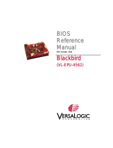
Functional Block Diagram
The block diagram shows all available SMARC-sXEL interfaces.
Figure 2: Block Diagram
SER0
CAN
GI1
ETH1
GI0
ETH0
LVDS
DP
DP++
(DDI1)
SPI 1
I2S
eDP/MIPI-DSI
PwrCtrl
SysMgmt SER1
SER3
SDIO
eSPI
SPI 0
HDMI
(DDI2)
PCIe #0-3
#3 optional
SGMII
SATA0
HDA
Intel® Atom™Embedded Elkhard-Lake
(Intel® Atom™Industrial Elkhard-Lake)
Intel® Celeron® Elkhard-Lake
Connector Option
Standard
component
VCC
VBAT
HWM
USB
#0-#1
#3-#5
(USB 2.0)
PWM
FAN1
I2C
SMB
LID
Sleep 14x G PIO
Embedded Controller
(CPLD EPM1270 or newer
generation)
HWM
CPU FAN0
Power sequencing
Watchdog
eSPI2I2C
I2C
EEPROM
USB 3.0
Host and
OTG (#3)
Intel
Gen11
iGFX
USB 2.0
Host
SPI
BIOS Flash
GPIO
UART
Ctrl
Mgmt
I2C
GPIO Buffer
SMARC 2.1 pinout connector
UART
eDP2LVDS
USB #2-3
(USB 3.0)
LPDDR4-4267 memory down (up to
16GB – IB-ECC)
Level-
shifter
TPM
2.0
Opt. SGMII
on PCIe #3
+ MDIO
PHY
PHY
eMMC
eMMC(5.1)
4-64GB
TPM 2.0
(SLB9670)

SMARC-sXEL - User Guide Rev. 1.4
www.kontron.com // 19
Top Side Features
Figure 3: Top Side
1
SMARC 2.1 connector
2 Multi-Chip Package (MCP)
3 4x LPDDR memory down
4
3-pin fan connector
5 Mounting points
Rear Side Features
Figure 4: Rear Side
1 SMARC 2.1 connector
2 Product labelling
4
3
2
1
5
5
5
5
2
1

SMARC-sXEL - User Guide Rev. 1.4
www.kontron.com // 20
Component Main Data Specification
Table 3: Component Main Data
SMARC-sXEL
Form factor Short module form factor: 82 mm x 50 mm, max. thickness 6 mm
Processor Intel® Atom®/Pentium®/Celeron® 6xxx processor family
Main Memory Up to 16 GByte LPDDR4 memory down with in-band ECC support
Storage (eMMC 5.1 Flash) Up to 128 GByte MLC or option for up to 64 GB pSLC
Graphics controller Intel® UHD Gfx Gen11
SPI Boot flash 32 MByte SPI Flash chip (Winbond W25Q256JW)
Eeep Embedded EEPROM stores modules parameters. Operates at 1.8V
(I2C slave Address A0 hex 8-bit format or 50 hex 7-bit format)
Power Management C-states: C0, C1, C6, C7, C8, C9, C10
Power Management CARIER_PWR-ON, CARRIER-STBY_ON; POWER-BTN; LID;
SLEEP; RESET_OUT; RESET_IN; VIN-PWR-BAD and BATLOW
SMARC I/O System Interconnection
Ethernet Up to 3x 1 GbE (2x GBE0/1 and 1x optional SGMII via SERDES)
Storage 1x SATA 6Gb/s
PCI Express® Up to 4x PCIe x1 or
Option: 3x PCIe and 1x SERDES
Panel Signal 1x LVDS dual channel (on request eDP)
1x DP++
1x HDMI (on request DP)
USB 2x USB 3.1 5Gb/s (incl. USB 2.0)
4x USB 2.0 (USB 2 port 3 as dual role client host)
Serial 3x Serial interfaces (2x RX/TX only)
Other Features
TPM Integrated TPM 2.0 capability of the Intel Platform Trust Technology (Intel PTT).
Also known as firmware TPM (fTPM).
Watchdog timer Watchdog timer supported by WDT_TIME_OUT
Audio HD audio and I2S interfaces
I2C Bus 2x I2C
SMBus HWM Nuvoton NCT7802Y (SM-Bus address: 5Ch)
SPI 2x SPI
GPIO 14x GPIO
On-Module Connectors
Sys-Fan Fan connector used to control fan speed operates from (3.3 V to 5.25 V input)
Power
Power Supply 3.3 V to 5.25 V wide-range input (5 V recommended)
Software
Operating system Support Board Support Packages ((BSP) will be made available for:
Windows® 10
Enterprise, Windows® 10 IoT
Linux
BIOS AMI Aptio V
Page is loading ...
Page is loading ...
Page is loading ...
Page is loading ...
Page is loading ...
Page is loading ...
Page is loading ...
Page is loading ...
Page is loading ...
Page is loading ...
Page is loading ...
Page is loading ...
Page is loading ...
Page is loading ...
Page is loading ...
Page is loading ...
Page is loading ...
Page is loading ...
Page is loading ...
Page is loading ...
Page is loading ...
Page is loading ...
Page is loading ...
Page is loading ...
Page is loading ...
Page is loading ...
Page is loading ...
Page is loading ...
Page is loading ...
Page is loading ...
Page is loading ...
Page is loading ...
Page is loading ...
Page is loading ...
Page is loading ...
Page is loading ...
Page is loading ...
Page is loading ...
Page is loading ...
Page is loading ...
Page is loading ...
Page is loading ...
Page is loading ...
Page is loading ...
Page is loading ...
Page is loading ...
Page is loading ...
Page is loading ...
Page is loading ...
Page is loading ...
Page is loading ...
Page is loading ...
Page is loading ...
Page is loading ...
Page is loading ...
Page is loading ...
Page is loading ...
Page is loading ...
Page is loading ...
Page is loading ...
Page is loading ...
Page is loading ...
Page is loading ...
Page is loading ...
Page is loading ...
Page is loading ...
Page is loading ...
Page is loading ...
Page is loading ...
Page is loading ...
Page is loading ...
Page is loading ...
Page is loading ...
Page is loading ...
Page is loading ...
Page is loading ...
Page is loading ...
Page is loading ...
Page is loading ...
Page is loading ...
Page is loading ...
Page is loading ...
Page is loading ...
Page is loading ...
Page is loading ...
Page is loading ...
Page is loading ...
Page is loading ...
/