Page is loading ...

HDMI cable passed through hole cut out in
rubber grommet. Remove rubber, cut hole,
push the cable(s) through and replace
grommet with cable into the insert.
3. Dual gang
plastic outlet
box, new work
INS00847 REV. D 11/10
MIW-SURGE
Installation Instructions
PFPower, 1690 Corporate Circle • Petaluma, CA 94954
707-283-5900 • 800-472-5555 • Fax - 707-283-5901
www.panamax.com • www.furmansound.com
Customer Relations
7:30 AM – 4:30 PM, M-F, Pacific Time (PST)
Email - [email protected]
By
Panamax
~
Furman
By
Panamax
~
Furman
5. Decora® trim
plate adapter
6. Keystone module
insert
7. 11” Flat Plug
adapter power cord
8. Three wire
twist nuts
9. Wall cut out tem-
plate 3 3/4” H x 4” W
AC Circuit
AC Outlets, Total: ............................................................................1
Line Voltage: ..............................................................120V, 50/60Hz
Total Current Capacity: ................................................................15A
Protection Modes: ........................................................L-N, L-G, N-G
Energy Dissipation: .........................................................1350 Joules
Peak Impulse Current: ..............................................................60 KA
Catastrophic Surge Circuit: ..........................................................Yes
Thermal Fusing: ..........................................................................Yes
UL 1449 2nd Ed. Suppressed Voltage Rating: ..............330 V (@500A)
UL 1449 3rd Ed. Voltage Protection Rating: ..............400 V (@3,000A)
UL 1449 3rd Ed. Nominal Discharge Current: ......................... 5,000A
Power Outlet Faceplate
AC Connectors: ...........................................................1 NEMA 5-15
Signal Line Protection: Not Included / Modules Sold Separately
PRODUCT SPECIFICATIONS
The MIW-SURGE is designed essentially for compatibility with three basic configurations:
PFPower warrants to the purchaser of any
PFPower In-Wall surge protector, for a pe-
riod of 3 years from its installation date,
that the surge protector shall be free of
defects in design, material, or workman-
ship, and PFPower will repair or replace
any defective unit. For product replace-
ment see “NOTIFICATION” below.
CAUTION: Audio/Video, computer and/
or telephone system installations can be
very complex systems, which consist of
many interconnected components. Due
to the nature of electricity and surges, a
single protector may not be able to com-
pletely protect complex installations. In
those cases, a systematic approach using
multiple protectors must be employed.
Systematic protection requires profes-
sional design. AC power, satellite cables,
CATV cables, or telephone/network lines
entering the system that do not pass
through this surge protector will provide
pathways for potential surge damage. For
additional information on how to protect
your system, please contact PFPower
before connecting your equipment to the
surge protector. More detailed informa-
tion is available at www.panamax.com or
www.furmansound.com. If you have any
questions regarding these requirements,
please contact PFPower Customer Rela-
tions.
1. PROPER INSTALLATION: PFPower
In-Wall AC and Signal-line protectors are
designed to provide code-compliant (NEC
or CEC) installations. Separate signal-line
protection modules must be used with the
appropriate AC base unit to provide proper
grounding. Building wiring and other con-
nections to protected equipment must
conform to applicable codes (NEC or CEC).
No other ground wires or ground connec-
tions may be used. All wires (including,
AC power lines, telephone lines, signal/
data lines, coaxial cable, antenna lead-
ins) leading into the protected equipment
must first pass through a single PFPower
protector designed for the particular ap-
plication. The protector and the equip-
ment to be protected must be indoors in
a dry location, and in the same building.
PFPower installation instructions and dia-
grams must be followed.
2. NOTIFICATION: You must obtain a re-
turn authorization (RA) number from the
PFPower Customer Relations Department
at www.panamax.com or www.furman-
sound.com or toll-free at 1-800-472-
5555 before returning the protector to
PFPower. Once you obtain an RA number,
please mark the number on the bottom of
the unit and pack it in a shipping carton/
box with enough packing material to pro-
tect it during transit. The RA number must
be clearly marked on the outside of the
carton. Ship the unit to PFPower. Please
note that you are responsible for any and
all charges related to shipping the unit to
PFPower.
3. DETERMINATION OF FAILURE:
PFPower will evaluate the protector for
defects. Opening the enclosure, tamper-
ing with, or modifying the unit in any way
shall be grounds for an automatic denial
of your request for replacement. PFPower,
after evaluating the unit, shall in its sole
discretion, determine whether or not your
protector is eligible for replacement. If the
surge protector shows no defects, PF-
Power will return the unit to you with a let-
ter explaining the test results. Exception: If
a dealer or installer replaces the protector
for the customer, the unit will be returned
to the dealer or installer.
4. GENERAL: If you have any questions
regarding the product warranty, please
contact the Customer Relations Depart-
ment at www.panamax.com or www.
furmansound.com or toll-free at 1-800-
472-5555. This warranty supersedes
all previous warranties. This is the only
warranty provided with the protector and
any other implied or expressed warranties
are non-existent. This warranty may not
be modified except in writing, signed by
an officer of PFPower.Forms are available
on the Panamax or Furman web sites for
requesting RA’s.
MODEL - MIW-SURGE
DOC. NO. Q01L0047_EN REV. A
Effective Date 6/08
WARRANTY
MIW PRO SIGNAL LINE MODULES
1. MIW-5RCA
Low voltage module with 5 RCA connec-
tions compatible with component video or
composite audio/video signal.
2. MIW-VGA
Low voltage module for RGBHV; connect
devices to 15 pin high-density D-sub
connector on face of module; 3.5mm
stereo mini-jack for 12-volt triggering
and IR signal transmission.
3. MIW-SVIDEO
Combination S-Video and Component Video,
low voltage module for video and/or audio,
RCA jacks compatible with audio or video
signals.
4. MIW-DATA
RS232 and Ethernet, low Voltage module
for projector control lines and/or computer
data lines.
The MIW Pro Signal Line modules give you 4 options to choose from.
Each signal line module comes with an instructions for easy install.
The MIW Pro Signal Line modules are not included and sold separately from PFPower.
Contact Panamax or Furman to order module(s) and other products you may need.
1. PASS THROUGH INSERT
with rubber grommet accomo-
dates HDMI, RGB, or coaxial
cables.
2. KEYSTONE 2 PORT
ADAPTER INSERT
with module selection. NOTE: If using
a punchdown connector, punch down
wires first before inserting module
into KEYSTONE insert. (Modules for
KEYSTONE adapter insert are sold sepa-
rately and not available from PFPower)
3. DECORA TRIM ADAPTER
for 6 port insert for a variety of signal
line connections.
(6 port insert and modules are sold sepa-
rately and not available from PFPower)
4. MIW PRO SIGNAL LINE
MODULES
Four module types available.
1. MIW-RCA 2. MIW-VGA
3. MIW-SVIDEO 4. MIW-DATA.
(Modules not included, sold separately
and available from PFPower, see below for
module descriptions).
Adjustable 3 depth settings for:
• PASS THROUGH INSERT
• KEYSTONE ADAPTER
• ALL 4 MIW PRO SIGNAL LINE MODULES.
3. 1 inch deep
1. Flush with
faceplate
2. 1/2 inch deep
Remove PASS THROUGH INSERT ASSEMBLY
(cage) and place Decora 6 port insert
with modules you need onto the
front of the mounting bracket .
Place Decora trim plate
adapter over the Decora insert.
Use the 2 screws/lock nuts
that attached the PASS THROUGH
INSERT.
Remove the black rubber grommet
from the PASS THROUGH INSERT
and snap KEYSTONE adapter into
open slot.
To install MIW PRO
SIGNAL LINE MODULES,
simply remove insert
from assembly and
insert the MODULE.
Insert
Remove
1. Single gang
plastic outlet
box, retro
2. Single gang
metal outlet
box, new work
1. MIW-SURGE metal
outlet faceplate (AC
receptacle attached)
2. 4 flathead faceplate
screws and 2 pan head
screws for bracket
3. MIW-SURGE plastic
mounting bracket
4. MIW pass through
removable and adjust-
able insert with rubber
grommet (comes at-
tached to mounting
bracket)
PARTS INCLUDED:
Outlet boxes are NOT included and are sold separately.
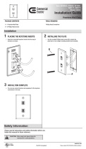
TOOLS RECOMMENDED:
• Drywall saw or Dremel tool (to cut outlet box hole)
• Hand held or power screw driver with Phillips head
• File (optional) to smooth and shape the outlet box cutout (if necessary)
• Utility knife
• Combination strippers
• Long nosed pliers
SIGNAL LINE CONNECTION OPTIONS
Installation instructions for using MIW-SURGE with
G
N
L
G
N
L
15 Amp
Circuit Breaker
Electric Panel
MIW-SURGE
Minimum
14 Gauge Wire
US PATENT NOS.
6,932,624 6,979,205 7,271,991 US PATENT PENDING
CAUTION: USE ONLY IN DRY (INDOOR) LOCATIONS.
ATTENTION: PAR L’USAGER A L’INTERÉRIEUR.
WALL MOUNTING THICKNESS 3/8” - 5/8”
MIW-SURGE
MIW-XT
L
N
G
BLACK
WHITE
GROUND
Suppressed Voltage Rating: 330V @ 500A
Voltage Protection Rating: 400V @ 3KA
US PATENT NOS.
6,932,624 6,979,205 7,271,991
5
6
1

Determine which outlet box for AC power and signal line connections your installation requires.
1. Determine where to place the MIW-SURGE.
Locate where the unit is to be installed and trace
the outline of the cutout hole with the included tem-
plate. (3 3/4” H x 4” W) for the plastic single gang.
2. Using drywall saw, cut out opening along the
drawn lines. If necessary use a file to enlarge the
opening.
3. Bend the two lower wire clamps down on the
bottom, rear of the box to make clearance for the
MIW-SURGE and for Romex cord.
4. Pull through Romex cord and dress accord-
ingly. No more than 1” of sheath should extend
into the outlet box. 2” to 3” of the hot, neutral
and ground wires should extend beyond that.
5. Insert the single gang plastic outlet box into the
left-hand side of the hole and secure the drywall
clamps.
SINGLE GANG PLASTIC OUTLET BOX - RETRO
1.
It’s most likely the metal outlet box is already
installed in the wall as shown here. Using the
template, align the left side of the existing cutout
hole with the left edge of template and draw a line
around the template. The total width of the cut out
hole should be 4” across.
2. Using the drywall saw, cut along the line to
enlarge the cut out hole.
3. Follow STEPS 3 through 11 from the SINGLE
GANG PLASTIC OUTLET BOX instructions to install
the MIW-SURGE.
BEFORE YOU GET STARTED
CAUTION
Only use with 15 Amp branch circuits utilizing 14 or 12 gauge wire. Make sure the branch
circuit is de-energized before installation.
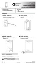
6. Before attaching the MIW-SURGE mounting
bracket, determine which signal line connection
is to be utilized. Remove or adjust the depth of
the insert, or the entire insert assmbly if needed.
For signal line instructions, see Panel 5 for
SIGNAL LINE CONNECTION OPTIONS.
7. After the signal line connection is completed,
attach the MIW-SURGE plastic mounting bracket
to the outlet box with the two panhead screws.
8. Fold the wires as shown to help make
clearance for the faceplate assembly to fit
into outlet box.
9. Twist the hot (black), neutral (white) and
ground (green) wires from the MIW-SURGE to
the three corresponding stripped wires from the
Romex. Connect the splices with the included
yellow wire nuts.
10. Attach the MIW-SURGE faceplate to the
mounting bracket with the 4 flat head screws.
11. Plug in the Flat Plug AC cord to be con-
nected to equipment. The picture shown here
indicates using the HDMI cable as an example
only (Many different options are available).
SINGLE GANG METEL OUTLET BOX - NEW WORK
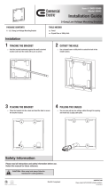
DUAL GANG PLASTIC OUTLET BOX - NEW WORK
Materials Required
• MIW-SURGE unit
• Outlet box, Carlon B114R (plastic
retro-fit) not included, sold separately
Materials Required
• MIW-SURGE unit
• Metal outlet box, Raco 8355 (not included, sold separately).
Materials Required
• MIW-SURGE unit
• Carlon dual gang plastic outlet box,
(not included, sold separately).
1. Most likely the dual gang outlet box is already
installed in the wall as shown here.
2. Follow STEPS 3 through 11 from the SINGLE
GANG PLASTIC OUTLET BOX instructions to install
the MIW-SURGE.
Installation instructions for using MIW-SURGE with
Installation instructions for using MIW-SURGE with
Installation instructions for using MIW-SURGE with
2 3 4
/