Page is loading ...

Vantage Pro
®
Weather Envoy
Installation Manual
Product # 6314 & 6314C
Envoy_front_cover D005.fm Page 1 Monday, November 11, 2002 7:43 AM

3465 Diablo Avenue, Hayward, CA 94545-2778 U.S.A.
510-732-9229 • Fax: 510-732-9188
E-mail: [email protected] • www.davisnet.com
Product #: 6314 & 6314C
Part Number: 7395.181
Weather Envoy Installation Manual
Rev A Manual (September 26, 2002)
This product complies with the essential protection requirements of the EC EMC Directive 89/
336/EC..
(c) Davis Instruments Corp. 2002. All Rights Reserved.
FCC Part 15 Class B Registration Warning
This equipment has been tested and found to comply with the limits for a Class B digital
device, pursuant to Part 15 of the FCC Rules. These limits are designed to provide rea-
sonable protection against harmful interference in a residential installation. This equip-
ment generates, uses, and can radiate radio frequency energy and, if not installed and
used in accordance with the instructions, may cause harmful interference to radio com-
munications.
However, there is no guarantee that interference will not occur in a particular installation.
If this equipment does cause harmful interference to radio or television reception, which
can be determined by turning the equipment on and off, the user is encouraged to try to
correct the interference by one or more of the following measures:
• Reorient or relocate the receiving antenna.
• Increase the separation between the equipment and receiver.
• Connect the equipment into an outlet on a circuit different from that to
which the receiver is connected.
• Consult the dealer or an experienced radio/TV technician for help.
Davis cables must be used for this equipment to comply with the relevant FCC regula-
tions.Changes or modification not expressly approved in writing by Davis Instruments
may void the warranty and user’s authority to operate this equipment.
Envoy_front_cover D005.fm Page 2 Monday, November 11, 2002 7:43 AM

Table of Contents
i
Table of Contents
Welcome to the Weather Envoy! . . . . . . . . . . . . . . . . . . .1
Contents . . . . . . . . . . . . . . . . . . . . . . . . . . . . . . . . . . . . . . . . . . . . . . . .1
Required for Operation . . . . . . . . . . . . . . . . . . . . . . . . . . . . . . .1
All Weather Envoys: . . . . . . . . . . . . . . . . . . . . . . . . . . . . . . .1
Wireless Weather Envoy: . . . . . . . . . . . . . . . . . . . . . . . . . . .1
Cabled Weather Envoy: . . . . . . . . . . . . . . . . . . . . . . . . . . . .1
Optional Accessories . . . . . . . . . . . . . . . . . . . . . . . . . . . . . .2
Hardware Installation . . . . . . . . . . . . . . . . . . . . . . . . . . . .2
Hardware Requirements . . . . . . . . . . . . . . . . . . . . . . . . . . . . . . . . . . . .2
Local Connection Windows Computer Requirements . . . . . . . .2
Local Connection Macintosh Computer Requirements . . . . . . .2
Preparing the Envoy . . . . . . . . . . . . . . . . . . . . . . . . . . . . . . . . . . . . . . .3
Installing the Data Logger . . . . . . . . . . . . . . . . . . . . . . . . . . . . .3
Installing the Batteries . . . . . . . . . . . . . . . . . . . . . . . . . . . . . . . .4
Connecting AC Power . . . . . . . . . . . . . . . . . . . . . . . . . . . . . . . .5
Connecting a Cabled Envoy to the Integrated Sensor Suite (ISS) 5
Mounting the Envoy . . . . . . . . . . . . . . . . . . . . . . . . . . . . . . . . . .6
Local Computer Installation . . . . . . . . . . . . . . . . . . . . . . . . . . . . . . . . . .7
Installing with a Local Computer . . . . . . . . . . . . . . . . . . . . . . . .7
Remote Computer Installation . . . . . . . . . . . . . . . . . . . . . . . . . . . . . . . .8
Remote Modem Connection Hardware Requirements . . . . . . .8
Installing with a Remote Computer . . . . . . . . . . . . . . . . . . . . . .9
A Few Notes About Phone Modem Connections . . . . . . . . . . . .9
Software Installation and Setup . . . . . . . . . . . . . . . . . . .10
Installing the Software . . . . . . . . . . . . . . . . . . . . . . . . . . . . . . . . . . . . . .10
Windows Computer . . . . . . . . . . . . . . . . . . . . . . . . . . . . . . . . . .10
Macintosh Computer . . . . . . . . . . . . . . . . . . . . . . . . . . . . . . . . .10
Running the Software . . . . . . . . . . . . . . . . . . . . . . . . . . . . . . . . . . . . . .10
Station Setup . . . . . . . . . . . . . . . . . . . . . . . . . . . . . . . . . . . . . . . . . . . . .10
Adding a Station . . . . . . . . . . . . . . . . . . . . . . . . . . . . . . . . . . . .10
About the Walkthrough . . . . . . . . . . . . . . . . . . . . . . . . . . . . . . .11
New Station . . . . . . . . . . . . . . . . . . . . . . . . . . . . . . . . . . . . . . . .12
Station Configuration . . . . . . . . . . . . . . . . . . . . . . . . . . . . . . . . .13
Serial Port . . . . . . . . . . . . . . . . . . . . . . . . . . . . . . . . . . . . . . . . .14
Configure Console . . . . . . . . . . . . . . . . . . . . . . . . . . . . . . . . . . .15
Select Units . . . . . . . . . . . . . . . . . . . . . . . . . . . . . . . . . . . . . . . .16
Set Barometer . . . . . . . . . . . . . . . . . . . . . . . . . . . . . . . . . . . . . .17
WE GSG TOC D007.fm Page i Monday, November 11, 2002 7:44 AM

Table of Contents
ii
Set Rain Cal . . . . . . . . . . . . . . . . . . . . . . . . . . . . . . . . . . . . . . .18
Set Temp & Hum Cal . . . . . . . . . . . . . . . . . . . . . . . . . . . . . . . . . 18
Set Total Rain . . . . . . . . . . . . . . . . . . . . . . . . . . . . . . . . . . . . . . 19
Set Time . . . . . . . . . . . . . . . . . . . . . . . . . . . . . . . . . . . . . . . . . .19
Set Archive Interval . . . . . . . . . . . . . . . . . . . . . . . . . . . . . . . . . .20
Set Latitude and Longitude . . . . . . . . . . . . . . . . . . . . . . . . . . . . 20
Set Alarms . . . . . . . . . . . . . . . . . . . . . . . . . . . . . . . . . . . . . . . . .22
Auto Download . . . . . . . . . . . . . . . . . . . . . . . . . . . . . . . . . . . . .23
Alarms . . . . . . . . . . . . . . . . . . . . . . . . . . . . . . . . . . . . . . . 24
Three special alarms . . . . . . . . . . . . . . . . . . . . . . . . . . . . . . . . . . . . . . .25
Weather Data Measured & Calculated . . . . . . . . . . . . . . 25
Wind . . . . . . . . . . . . . . . . . . . . . . . . . . . . . . . . . . . . . . . . . . . . . . . . . . . 25
Temperature . . . . . . . . . . . . . . . . . . . . . . . . . . . . . . . . . . . . . . . . . . . . .25
Apparent Temperatures . . . . . . . . . . . . . . . . . . . . . . . . . . . . . . . . . . . . 25
Humidity . . . . . . . . . . . . . . . . . . . . . . . . . . . . . . . . . . . . . . . . . . . . . . . .26
Dew-Point . . . . . . . . . . . . . . . . . . . . . . . . . . . . . . . . . . . . . . . . . . . . . . . 27
Rainfall . . . . . . . . . . . . . . . . . . . . . . . . . . . . . . . . . . . . . . . . . . . . . . . . .27
Barometric Pressure . . . . . . . . . . . . . . . . . . . . . . . . . . . . . . . . . . . . . . . 27
Solar Radiation . . . . . . . . . . . . . . . . . . . . . . . . . . . . . . . . . . . . . . . . . . .28
UV (Ultra Violet) Radiation . . . . . . . . . . . . . . . . . . . . . . . . . . . . . . . . . . 28
EvapoTranspiration (ET) . . . . . . . . . . . . . . . . . . . . . . . . . . . . . . . . . . . . 31
Leaf Wetness . . . . . . . . . . . . . . . . . . . . . . . . . . . . . . . . . . . . . . . . . . . .31
Soil Moisture . . . . . . . . . . . . . . . . . . . . . . . . . . . . . . . . . . . . . . . . . . . . . 31
Time . . . . . . . . . . . . . . . . . . . . . . . . . . . . . . . . . . . . . . . . . . . . . . . . . . .31
Troubleshooting Guide . . . . . . . . . . . . . . . . . . . . . . . . . . 32
Communications Problems . . . . . . . . . . . . . . . . . . . . . . . . . . . . . . . . . . 32
Finding the Correct Serial Port . . . . . . . . . . . . . . . . . . . . . . . . . . . . . . . 33
Modem Initialization String . . . . . . . . . . . . . . . . . . . . . . . . . . . . . . . . . . 34
Program Problems . . . . . . . . . . . . . . . . . . . . . . . . . . . . . . . . . . . . . . . . 34
Contacting Davis Technical Support . . . . . . . . . . . . . . . . . . . . . . . . . . .35
Specifications . . . . . . . . . . . . . . . . . . . . . . . . . . . . . . . . . . . . . . . . . . . .36
WE GSG TOC D007.fm Page ii Monday, November 11, 2002 7:44 AM

WELCOME TO THE WEATHER ENVOY!
Contents
1
Welcome to the Weather Envoy!
Welcome to Davis Instruments’ Weather Envoy! The Weather Envoy provides a
new and exciting way of getting your Davis weather station data into your
Windows (95 or later) or Macintosh (OS X) computer.
The Weather Envoy includes the data collection and logging functions of the Van-
tage Pro console, but in a smaller package that can be discreetly placed next to
your computer. Both cabled and wireless versions of the Weather Envoy are avail-
able. In combination with our WeatherLink software, the Weather Envoy allows
you to view, store, plot, analyze, export, share and print your weather data.
Contents
Before continuing, please be sure your Weather Envoy package includes the
following:
▲ Envoy console
▲ Two #6 x 1” screws for wall mounting
▲ AC-power adapter
Required for Operation
In order to use your Weather Envoy, you will also need the following Davis
weather products:
All Weather Envoys:
▲ WeatherLink for Vantage Pro (Windows version 5.2 or later (#6510C), Mac OS
X version 5.01 or later (#6520C))
Wireless Weather Envoy:
▲ Wireless Integrated Sensor Suite (ISS) or ISS Plus
or
▲ Wireless Vantage Pro (Plus) Weather Station
Cabled Weather Envoy:
▲ Cabled ISS or Cabled ISS Plus

HARDWARE INSTALLATION
Optional Accessories
2
Optional Accessories
The following optional accessories are designed for use with your Envoy. They
are available from your dealer or may be ordered directly from Davis.
▲ Telephone Modem Adapter (#6533)
Allows transmission of data from the data logger using a modem.
▲ Standard 4-Conductor 40’ Extension Cable (#7876-040)
For more flexibility in the placement of your Weather Envoy, add one 40’
(12 m) extension cable to extend the distance between your station and the
computer. (48’ (14.4 m) maximum)
Hardware Installation
The Weather Envoy allows two types of installation: local connection to a
computer and remote connection to a computer via a modem. Requirements and
installation for each type of connection differ, and are explained separately below.
Hardware Requirements
Note: The amount of storage space necessary for the data files depends on the archive
interval. Each archive record in the database is 88 bytes. Every day in the database
has an additional two records totalling 176 bytes that store daily summary informa-
tion. A database containing data stored at a 30-minute archive interval requires
approximately 4400 bytes of disk space per day or 132KB of disk space per month.
The disk space requirements change in a linear fashion depending on the archive
interval. For example, data stored at a one-minute interval requires approximately 3.8
MB a month while data stored at a two-hour interval requires approximately 32 KB a
month.
Local Connection Windows Computer Requirements
Your Weather Envoy requires the following for a local Windows computer
connection:
▲ Computer running Windows™ 95, 98, 2000, XP, ME, or NT 4.0 with at least 5
MB of free disk space
▲ Windows-compatible display
VGA minimum. SVGA or High (16-bit) Color or better recommended.
▲ One free serial port
Local Connection Macintosh Computer Requirements
Your Weather Envoy requires the following for a local Macintosh computer
connection:
▲ Macintosh computer running Mac OS X v10.01 or newer with at least 5 MB of
free disk space
▲ A USB to serial port converter connected to a Macintosh USB port.

HARDWARE INSTALLATION
Preparing the Envoy
3
Preparing the Envoy
Perform the following procedures to prepare your Envoy for operation.
▲ Install the Data Logger
▲ Install the Batteries
▲ Mount your Envoy
▲ Make the Envoy Connections
▲ Test using WeatherLink
▲ Setup the Envoy using WeatherLink
Installing the Data Logger
CAUTION: The WeatherLink data logger must be installed before you install the
batteries!
1. Remove the three screws from the back of the
Envoy case.
2. Separate the case halves to expose
the data logger connector.

HARDWARE INSTALLATION
Preparing the Envoy
4
3. Carefully insert the data logger into the connector.
Note:Be sure to push down firmly on the data logger to seat the connection.
4. Rejoin the case halves, making sure the data logger cable passes through the
cable channel.
5. Fasten using the three screws you previously removed.
Installing the Batteries
CAUTION: The WeatherLink Data Logger must be installed before you install the
backup batteries!
1. Find the battery cover on the back side of the Envoy case.
2. Remove the battery cover by pressing on the arrow embossed on the cover
and sliding the cover away from the case.
Data Logger Cable Channel
Data Logger
Installing the Data Logger
Installing the Batteries

HARDWARE INSTALLATION
Preparing the Envoy
5
3. Insert the three AA-cell batteries, negative terminal (flat side) first.
The Envoy will run through a brief self-test procedure. If the test is successful
you will hear two (2) beeps.
4. Replace the battery cover on the case.
Note: Operating on battery power alone, the Cabled Weather Envoy will run approximately
10 days and the Wireless Weather Envoy will run approximately 5 months.
Connecting AC Power
CAUTION: The WeatherLink Data Logger and the backup batteries must be
installed before you connect AC power!
1. Locate the power adapter jack on the end of the Envoy case. It’s next to the
data logger output cable.
2. Insert the power adapter plug into the power jack.
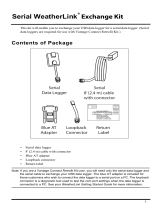
Connecting a Cabled Envoy to the Integrated Sensor Suite (ISS)
Refer to the figure shown in above “Connecting AC Power”.
1. Insert the modular plug into the ISS jack on the Envoy case.
You won’t be able to test the connection between the Envoy and the ISS until
you have finished installing the WeatherLink software.
AC Power
Adapter
Power
Jack
From Integrated
Sensor Suite
(cabled models only)
To
Computer
Envoy
Data Logger
Power, Sensor, and Computer Connections

HARDWARE INSTALLATION
Preparing the Envoy
6
Mounting the Envoy
You can install your Envoy on your desktop or on the wall next to your computer.
Note: Whenever you first install the Weather Envoy, place the antenna in a vertical position.
If necessary, you can adjust the angle for best reception after it’s installed.
Use this procedure for a wall installation.
1. Find the template located on the next page.
2. Hold the template against the wall where you want to mount the Envoy, and
use a pencil to mark the location for the two mounting screws.
The screws should be 3.25” (82.5mm) apart and lined up vertically.
3. Drill the marked locations with a 3/32” or 7/64” ( 2.2 to 2.7 mm) drill bit.
4. Drive the two #6 x 1” (~ 3.5mm x 25mm) pan head self-threading screws into
the wall.
Leave at least a 1/8” (~ 3mm) space between the wall and the heads of the
screws.
5. Slide the keyholes on the back of the case over the two screw heads.
#6 x 1"
Pan-Head
Screws
Wall Mounting the Weather Envoy
3.25"
(82.55mm)
Drill 3/32"
or 7/64"
(~2.2 to 2.7mm)
Holes
Wall Mounting Template

HARDWARE INSTALLATION
Local Computer Installation
7
Local Computer Installation
The instructions below explain how to make a typical local connection. Note that
if you extend the cable run beyond 48’ (14.4 m), the software may have difficulty
communicating with the station.
Note: Mac Users - Refer to your WeatherLink for Mac OS X Getting Started Guide for addi-
tional installation instructions.
Local Computer Installation
Installing with a Local Computer
1. Locate a free serial port on the back of your computer and connect the DB9 to
the port.
2. Insert the cable plug at the end of the short cable coming from the data logger
into the receptacle on the end of the 8’ cable. Then insert the cable plug on the
end of the 8’ cable into the DB9 adapter.
The cable connecting the data logger to the computer is 8’ (2.4 m) long. If you
need to place the station console more than 8’ from the computer, use a 40’ (12
m) standard 4-conductor extension cable (#7876-040). Do not attempt to use
more than 40’ of extension cable, or the data logger may have difficulty com-
municating with the computer.
Note: The Weather Envoy data logger does not need to be connected to the computer for
the logging to work. You can connect the cable to the computer when you’re ready to
download, then disconnect it if you want to place the Weather Envoy somewhere
else. However, the WeatherLink bulletin, summary, or real-time strip charts can be
displayed only while the Weather Envoy is attached to the computer.
9-Pin
Connector
(DB-9)
Optional 40' (12 m) 4-Conductor
Extension Cable and Coupler
8' (2.5 m) Cable
AC Power
Adapter
Weather Envoy
Data Logger

HARDWARE INSTALLATION
Remote Computer Installation
8
Remote Computer Installation
The illustration below shows a typical remote computer installation using a
modem. This involves connecting the data logger to the Weather Envoy and to a
modem at the station console site and connecting your computer’s modem to a
phone line, which will allow you to dial the Weather Envoy .
Note: Mac Users - Refer to your WeatherLink for Mac OS X Getting Started Guide for addi-
tional installation instructions
Note: Before installing the console and modem at a remote location, test the data logger
and connection first using a direct connection like that shown in the section above.
Remote Modem Connection Hardware Requirements
The following additional hardware is required for a phone modem connection.
▲ One internal or external modem connected to your computer
The modem must be Hayes
®
–compatible and run at 1200, 2400, 4800, 9600,
14400 or 19200 baud.
▲ One external modem to connect to the Weather Envoy data logger
The modem must be Hayes
®
–compatible and run at 1200, 2400, 4800, 9600,
14000 or 19200 baud.
▲ Telephone Modem Adapter
The Telephone Modem Adapter (#6533) provides the connection between the
Weather Envoy data logger and the modem.
Weather Envoy
with Data Logger
External
Modem
25-pin Telephone Modem
Adapter (#6533)
8 feet (2.5 m)
Data Logger Cable
(standard)
Windows Computer
External or
Internal Modem
Remote Computer Installation

HARDWARE INSTALLATION
Remote Computer Installation
9
Installing with a Remote Computer
1. Install and set up an internal or external modem (according to the instructions
supplied by the manufacturer) for use with your computer.
Make a note of the COM port used by the modem. You will need this informa-
tion when entering serial port settings for the station.
2. At the Weather Envoy site, put the external modem in a location where it can
connect to both the data logger and the phone jack.
Note: Both the modem and the Weather Envoy should be powered down at this time, if they
are not already turned off.
The cable connecting the data logger to the modem is 8’ (2.4 m) long. If you
need to mount the station console more than 8’ from the modem, use a 40’ (12
m) standard 4-conductor extension cable. Do not attempt to use more than 40’
of extension cable, or the data logger may have difficulty communicating with
the modem.
3. Plug the external modem into the phone jack.
4. Connect the Weather Envoy data logger to the modem.
5. Power up the modem.
6. Power up the Weather Envoy last.
A Few Notes About Phone Modem Connections
If you indicate a phone modem connection when setting up your station, the
software automatically dials the station whenever you initiate a program action
that requires the software to talk to the station.
While connected to a phone modem station, an “On-Line” icon appears in the
toolbar. This icon indicates that you are on-line and may be used to hang up a
remote connection. To hang up, click on the On-Line icon from the toolbar or
choose Hang Up from the File menu.
Toolbar with On-Line Icon
By default, WeatherLink will hang up the connection to the modem after one
minute without any communication with the station. Use the Serial Port dialog
box in the Setup menu of WeatherLink to change this default value. (See the
WeatherLink help files for more on this subject.)
Note: WeatherLink will not hang up the phone line if the Bulletin or Summary windows are
active.
On-Line Icon

SOFTWARE INSTALLATION AND SETUP
Installing the Software
10
Software Installation and Setup
Refer to the following procedure to install WeatherLink software on your
computer.
Installing the Software
Windows Computer
1. Place the Install Disk in your CD ROM drive.
2. The install program should start automatically. If the install program does not
start, choose Run from the Start menu, type D:\SETUP (or E:\SETUP, substi-
tuting the correct drive letter for D or E), and choose OK to begin the installa-
tion.
3. Follow the on-screen prompts to complete the installation.
Macintosh Computer
1. Place the Install Disk in your CD ROM drive.
2. Copy “install.sit” from the CD to your destop and open it.
The installation software will automatically extract itself.
3. Run “install”.
4. Follow the on-screen prompts to complete the installation.
Running the Software
To run the software, double-click on the WeatherLink icon. If you have no stations
in the program directory when you run the software, the software will prompt
you to add a station (see below for details). If you have more than one station in
the program directory when you run the software, the software will open the last
station accessed.
Station Setup
To interact with your station, you must add your station to WeatherLink’s database,
which means naming the station, configuring the software to work with that station
and with your computer hardware, and setting station values such as time,
barometric pressure, total rainfall, and calibration numbers.
Adding a Station
1. Choose New Station from the File menu.
The software opens the Add New Station dialog box.
2. Type the station name into the text box.
The station name may be up to 40 characters/spaces long. Note that the soft-
ware uses the first eight characters of the station name (not counting spaces or
punctuation marks) as the name of the directory into which it saves this sta-
tion’s database and configuration files. The first eight characters of each sta-
tion name must, therefore, be unique.

SOFTWARE INSTALLATION AND SETUP
Station Setup
11
3. Choose OK.
The software saves the station, creates a directory and subdirectories for that
station, and prompts you to indicate whether you want to enter the walk-
through procedure.
About the Walkthrough
The software includes a “Walkthrough” utility that steps you through most of the
station setup and configuration procedures. After adding a new station, the soft-
ware automatically asks you whether or not you want to be walked through the
configuration procedure. You can, of course, choose No and set up the station by
choosing all of the necessary commands from the menus. A Walkthrough com-
mand is included in the Setup menu that lets you begin this procedure at any
time.
Note: If you have a remote computer connection, then the software will automatically dial a
phone modem station when it is necessary.
Note: Mac Users - Your Walkthrough will be a little different. Please refer to your Weather-
Link for Mac OS X Getting Started Guide for Walkthrough information.
If you choose Yes to begin the Walkthrough, the software takes you through the
following dialog boxes:
▲
Station Configuration
Set station name, model, accessories, download options, and data file
extension.
▲
Serial Port Settings
Set COM port to which data logger is connected. Specify modem connec-
tion settings such as baud rate, phone number, and modem initialization
string.
▲
Configure Console
Use the Configure Console dialog box to set the DavisTalk transmitter ID
assignments, turn on and off the console retransmit function, set daylight
savings time, select start of the rain season, and enable or disable averag-
ing of temperatures over the archive period.
▲ Choose Units
Select units of measure in which station information is displayed.
▲
Set Barometer & Elevation
Set the barometric pressure and your elevation on the station and on the
software.
▲
Set Rain Calibration
Set the station’s rainfall calibration number.
▲
Set Temperature and Humidity Calibration
Adjust the temperature and humidity settings on your station if necessary.
▲
Enter Year-to-Date Rainfall
Set the rainfall amount on the station and on the software. You must enter
this information from the software if you want you station and software
readings to agree.
▲
Set Time and Date
Set the time and date on the station, software, and computer and make
sure all three are synchronized.

SOFTWARE INSTALLATION AND SETUP
Station Setup
12
Note:When you set the time and date, you will be prompted to clear your archive memory.
If you do not clear archive memory, you may end up with data stored at an incorrect
time or duplicate records. We recommend that you download before setting the time,
unless you are creating a brand new station or just adjusting the time, so you may
safely clear the archive memory.
▲ Set Archive Interval
Set the interval at which data will be stored in the data logger’s memory.
This will clear any data stored in the data logger.
▲
Set Latitude and Longitude
You must set the correct latitude and longitude for the station’s forecast,
moon phase, and sunrise and sunset algorithms to work correctly.
▲
Set Station Alarms
Set alarm thresholds on the station.
▲
Set Auto Download Time(s)
Specify the stations and the times at which you want data automatically
downloaded to your computer each day.
At each step in the Walkthrough procedure, the software will provide confirma-
tion boxes prompting you to indicate whether or not you wish to continue. To
continue, choose OK. To skip any step and move to the next, choose Skip. To can-
cel the entire Walkthrough procedure, choose Cancel.
New Station
Each station connected to the computer must have its own “station” within the
software. This tells the software into which database new data should be saved,
provides the necessary communication settings (serial port, etc.), and other
station-specific information.
1. Choose New Station from the File menu.
The New Station dialog box appears.
2. To add a station, type the desired station name (up to 40 characters/spaces)
into the Station Name text box and choose OK.
The software saves the station, creates a directory for that station using the
first eight characters in the station name (not including punctuation and
spaces), and prompts you to indicate whether you want to enter the Walk-
through procedure (see “About the Walkthrough” on page 11).
New Station

SOFTWARE INSTALLATION AND SETUP
Station Setup
13
Station Configuration
You may enter information which will help to identify a particular station and
select a number of station-specific settings.
1. Choose Station Config from the Setup menu or press Ctrl-C.
The Station Configuration dialog box appears.
2. Enter the following information:
▲
Name
Enter the desired station name in this text box. Note that when you first
create a station, the software uses the first eight characters of the station
name as the name of the directory into which it saves this station’s data-
base and configuration files. If you change the station name, the software
will prompt you to change the name of the station directory.
▲
Model
Select the weather station model from the drop-down list. Select “Vantage
Pro” or “Vantage Pro Plus” if the list does not include “Envoy”.
▲ Rain Collector
Select the increment in which the rain collector you use with the station
measures rainfall. If you do not have a rain collector, choose None.
▲
Optional Accessories
Check each of the listed optional sensors that are installed in your weather
station.
▲ Download Options
The software can automatically create a space-delimited text file contain-
ing two-days worth of data records after each download. To enable this
feature, check the box. The file is named “download.txt” and is saved into
the station directory.
Station Configuration

SOFTWARE INSTALLATION AND SETUP
Station Setup
14
Note: The “download.txt” file is written as a space-delimited file. The export feature avail-
able in the Browse Window produces a tab-delimited file.
3. When finished, choose OK.
The software saves the station configuration settings.
Serial Port
To communicate with the data logger and station you must select the serial port
you are using and enter the correct settings.
1. Choose Serial Port
from the Setup
menu or press Ctrl-
I.
The Serial Port Set-
tings dialog box
appears.
2. Enter the following
information:
▲
Serial Port
Select the serial
port to which
the data logger
or modem is
connected.
▲
Baud Rate
Set the baud
rate to 19200, the default baud rate for the Weather Envoy Data Logger.
▲ Hangup Wait Time
Enter the amount of time, in minutes, the program should wait before
hanging up the connection and releasing the serial port during an idle con-
nection. If, for example, you’ve dialed your station, downloaded data, and
then left the connection open without the bulleting or summary running,
the software will hang up the modem after the time you specify here. This
feature is useful if another program uses the modem or another program
accesses the data logger.
▲
Dial Up Connection
Select this check box to connect to the Weather Envoy by modem (remote
connection). Once you’ve selected this box, the grayed-out options in the
lower part of the dialog box will be activated.
▲
Weather Station Phone Number
Enter the phone number for the modem connected to the station (Weather
Envoy) in this box. Make sure to enter the area code and any necessary
prefixes (for example, 1, 011, etc.).
▲ Enter a comma (,) to force the modem to pause before dialing the next
digit. You may enter more than one comma to increase the length of
time for which the modem pauses.
▲ Enter a “w” to force the modem to wait for a dial tone before dialing
the next digit.
Serial Port

SOFTWARE INSTALLATION AND SETUP
Station Setup
15
▲ Modem Initialization String
The default modem initialization string should work in almost all cases:
AT &F S7=60 E Q V X4. Before changing the modem string, see “Modem
Initialization String” on page 34 for an explanation of what each part of the
string means.
▲ After Connect Wait
Controls the number of seconds the software waits after it has connected
to a remote station before sending the first command. If you are having
difficulty connecting to a remote statio, try increasing the wait time.
▲
Rotary Dial
Select this check box if you are have a remote connection to the station by
modem using a phone modem connection and your phone is rotary dial.
3. When finished selecting options, choose Test.
The software will check the connection to the station (or modem) using the
current settings and indicate whether or not it successfully connected to your
Weather Envoy. If you cannot connect to the station, you may use Loopback
(see “Finding the Correct Serial Port” on page 33) to determine the correct
serial port or make sure the serial port itself is actually working.
4. Once the serial port settings are correct, choose OK.
The software saves the serial port settings.
Configure Console
Use the Configure Console
dialog box to set the Davi-
sTalk transmitter ID assign-
ments, turn on and off the
Weather Envoy retransmit
function, set daylight sav-
ings time, select start of the
rain season, and enable or
disable averaging of tem-
peratures over the archive
period.
1. Choose Configure Console
from the Setup menu.
The Serial Port Settings dia-
log box appears.
2. Set the Station Types
Select the station type used
by each of the DavisTalk
transmitter IDs.
▲
Cabled Weather Envoys
must have Station No. 1
set to ISS.
▲ If you are using a Temp/
Hum station and no ISS,
select Temp/Hum (ISS).
▲ You can select CLEAR ALL to set all transmitters to Off.
Configure Console

SOFTWARE INSTALLATION AND SETUP
Station Setup
16
3. Set Retransmit
If you want your Weather Envoy to retransmit weather data, say to either a
Vantage Pro console or a Weather Echo, turn Retransmit ON by selecting the
transmitter ID number for the retransmitted signal.
4. Set Daylight Savings
Select your local time zone from the list.
You can manually turn on Daylight Savings by selecting On. If you select Auto
Detect Daylight Savings, daylight savings time will automatically turn on at
1 am on the first Sunday in April and turn off at 2 am on the last Sunday in
October, or will turn off the last Sunday in March in Europe and Australia. If
neither On or Auto Detect Daylight Savings are selected, Daylight savings is
set to off.
5. Set Rain Season Start
Enter the date on which to start the annual rain totals. The rain season will
start on the first day of the month you select.
6. Set Average Temp Over Archive Period
The defalt is to log the temperature at the end of the archive period.
7. When finished configuring the console, choose Set.
The software sets the alarms on the station console to match the settings in this
dialog box.
Select Units
You may select the units of measure in which data is displayed within the
software. All program windows (bulletin, summary, plots, database, etc.) display
data in the selected units of measure.
1. Choose Select Units from the Setup menu or press Ctrl-U.
The Choose Units dialog box appears.
2. Select the desired units of measure:
▲
Temperature: Fahrenheit (°F) or Celsius
(°C)
Wind chill, dew point, degree-days,
and heat index are all displayed in the
same unit of measure as temperature.
▲
Barometer: Inches of Hg (in),
Millimeters of Hg (mm), Millibars (mb),
or Hectopascals (hPa)
▲ Wind Speed: Miles per Hour (mph),
Knots (knot), Kilometers per Hour (km/
hr), or Meters per Second (m/s)
▲ Rain: Inches (in) or Millimeters (mm)
Rain and ET use the same units of
measure.
▲
Elevation: Feet (ft) or Meters (m)
Choose Units
/