Page is loading ...

Vantage Pro2
Weather Envoy Manual
™
For Vantage Pro2 & Vantage Pro2 Plus Weather Stations
™™
Davis Instruments, 3465 Diablo Avenue, Hayward, CA 94545 • 510-732-9229 • www.davisnet.com

Weather Envoy for Vantage Pro2 Manual
Rev. B, April 10, 2006
Document Part Number: 07395.281
For Vantage Pro2 Weather Envoys # 6316 & 6316C
Vantage Pro
®
and Vantage Pro2
™
are trademarks of Davis Instruments Corp., Hayward, CA.
© Davis Instruments Corp. 2006. All rights reserved.
Information in this document subject to change without notice.
3465 D
iablo
A
venue
, H
ayward
,
C
A 94545-2778
510-732-9229 ¥
F
ax
:
510-732-9188
E
-
mail
:
info
@
davi
s
net
.
c
om
¥
www
.
davi
s
net
.
c
om
FCC Part 15 Class B Registration Warning
This equipment has been tested and found to comply with the limits for a Class B digital device, pursuant to Part 15 of the FCC Rules.
These limits are designed to provide reasonable protection against harmful interference in a residential installation. This equipment
generates, uses, and can radiate radio frequency energy and, if not installed and used in accordance with the instructions, may cause
harmful interference to radio communications.
However, there is no guarantee that interference will not occur in a particular installation. If this equipment does cause harmful interfer-
ence to radio or television reception, which can be determined by turning the equipment on and off, the user is encouraged to try to cor-
rect the interference by one or more of the following measures:
• Reorient or relocate the receiving antenna.
• Increase the separation between the equipment and receiver.
• Connect the equipment into an outlet on a circuit different from that to which the receiver is connected.
• Consult the dealer or an experienced radio/TV technician for help.
Changes or modification not expressly approved in writing by Davis Instruments may void the warranty and void the user's authority to
operate this equipment.
IC: 378810-6312
EC EMC Compliance
This product complies with the essential protection requirements of the EC EMC Directive 89/336/EC.

1
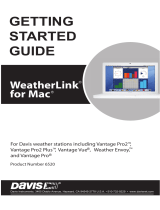
Welcome to the Weather Envoy!
Welcome to Davis Instruments’ Weather
Envoy
®
. The Weather Envoy provides a
new and exciting way of getting weather
data from your Vantage Pro2
™
weather sta-
tion and into your Windows (95 or later) or
Macintosh (OS X) computer.
The Weather Envoy
®
includes the data col-
lection and logging functions of the Van-
tage Pro2
™
console, but in a smaller
package that can be discreetly placed next to your computer. Both cabled and
wireless versions of the Weather Envoy are available. In combination with our
WeatherLink software and data logger, the Weather Envoy allows you to view,
store, plot, analyze, export, share, and print your weather data.
Contents
Before continuing, please be sure your Weather Envoy package includes the
following:
• Envoy
• Two #6 x 1” screws for wall mounting
• AC-power adapter
Required for Operation
You will also need the following Davis weather products to use your Envoy:
All Weather Envoys:
• Any version of WeatherLink for Vantage Pro and Vantage Pro2 (Windows
version 5.2 or later (6510USB, 6510SER, 6540, 6544, 6550, 6560,
6510C), Mac OS X version 5.01 or later (6520, 6520C))
Wireless Weather Envoy:
• Wireless ISS or ISS Plus (6320, 6322, 6325, 6328) or;
• Wireless Vantage Pro2 (Plus) Weather Station (6152, 6153, 6162, 6163)
Cabled Weather Envoy:
• Cabled ISS or Cabled ISS Plus (6322C and 6327C)
Optional Accessories
The following optional accessories are designed for use with your Envoy.
They are available from your dealer or may be ordered directly from Davis
Instruments.
• Telephone Modem Adapter (#6533) (For Serial Connections only) -
Allows transmission of data from the data logger using a modem.

Hardware Installation
2
• Standard 4-Conductor 40' Extension Cable (#7876-040) (For Serial
connections only) - For more flexibility in the placement of your Weather
Envoy, add one 40
' (12 m) extension cable to extend the distance between
your station and the computer. (48
' (14.4 m) maximum)
Hardware Installation
The Weather Envoy can be installed and connected to a computer two different
ways: via a local connection to a computer (using either the USB or serial
connection type) and remote connection to a computer via a modem.
Requirements and installation for each type of connection differ, and are
explained separately below.
Local Connection Windows Computer Requirements
WeatherLink is compatible with computers using a USB port connection
running the following platforms: 98 SE, ME, 2000 or XP.
WeatherLink is compatible with computers using a serial port connection
running the following platforms: 95 (with Internet Explorer 4.0 or higher), 98,
98 SE, ME, NT 4.0, 2000 or XP.
Your Weather Envoy and WeatherLink also require the following for a local
Windows computer connection.
• Windows-compatible display.
• VGA minimum. SVGA or High (16-bit) Color or better recommended.
• One free serial port or USB Port.
Local Connection Macintosh Computer Requirements
Your Weather Envoy requires the following for a local Macintosh computer
connection:
• Macintosh computer running Mac OS X v10.01 or newer with at least 5
MB of free disk space.
• One free USB Port.
Preparing the Envoy
Perform the following procedures to prepare your Envoy for operation.
• Install the Data Logger
• Install the Batteries and Optional AC power source
• Mount your Envoy
• Connect Envoy to WeatherLink software
• Test using WeatherLink software
• Setup the Envoy using WeatherLink software
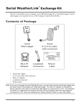
Install the Data Logger
Installing the data logger that is supplied with the WeatherLink package is the
first step in preparing the Weather Envoy to transmit data to the WeatherLink
software.

Install the Data Logger
3
CAUTION: Plugging or unplugging the data logger while power is applied to the Envoy can
lock up or damage the logger. The WeatherLink data logger must be installed
before you install the batteries.
1. Remove the three screws from the back of the Envoy case
2. Separate the case halves to expose the data logger connector.

Install the Batteries
4
3. Carefully insert the data logger (Serial or USB) into the connector slot,
making sure to push data logger firmly in place.
4. Rejoin the case halves, making sure the data logger cable passes through the
cable channel.
5. Fasten using the three screws you previously removed.
Install the Batteries
1. Find the battery cover on the back side of the Envoy case.
2. Remove the battery cover by pressing on the arrow embossed on the cover
and sliding the cover away from the case.
3. Insert the three AA-cell batteries, negative terminal (flat side) first. The
Envoy emits two beeps if the start up test is successful.
4. Replace the battery cover on the case.
Data Logger Cable Channel
USB Data Logger
Data Logger Cable Channel
Serial Data Logger

Mount Your Weather Envoy
5
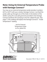
Optional: Connecting AC Power
The operating battery power for a cabled Weather Envoy is approximately 10
days. For a wireless Weather Envoy, the battery power is approximately 5
months. The Weather Envoy is supplied with an option AC power adapter that
can be installed as an optional power source.
Note: If installing the optional AC power supply, make sure the WeatherLink Data Logger is
already installed and that the backup batteries are installed
1. Locate the power adapter jack on the end of the Envoy case. It’s next to the
data logger output cable.
2. Insert the power adapter plug into the power jack.
Optional: Connecting a Cabled Envoy to the Integrated Sen-
sor Suite (ISS)
Refer to the figure shown above “Connecting AC Power”.
1. Insert the modular plug into the ISS jack on the Envoy case.
Note: You won’t be able to test the connection between the Envoy and the ISS until you
have finished installing the WeatherLink software.
Mount Your Weather Envoy
You can place your Envoy on your desktop, install it on a wall near your com-
puter, or install it with the optional Multi-Purpose Shelter (7728). Here are
some guidelines for placing your Weather Envoy.
AC Power
Adapter
Power
Jack
From Integrated
Sensor Suite
(cabled models only)
To
Computer
Envoy
Data Logger

Mount Your Weather Envoy
6
Envoy Location
You should place the Envoy in a location where it easily accessible and can be
easily connected to a computer. For more accurate readings, follow these sug-
gestions:
• Avoid placing the Envoy in direct sunlight. This may cause erroneous
inside temperature and humidity readings and may damage the unit.
• Avoid placing the Envoy near radiators or heating/air conditioning ducts.
• If you are mounting the Envoy on a wall, choose an interior wall. Avoid
exterior walls that tend to heat up or cool down depending on the weather.
The range of the radio transmission that the Envoy can receive from the wire-
less ISS depends on several factors. Try to position the Envoy around the
transmitting weather station as close as possible for best results.
Typical maximum ranges include:
• Line of sight: 1000 feet (300 m).
• Under most conditions: 200 - 400 feet (60 - 120 m).
Other range and transmission considerations include:
• Range may be reduced by walls, ceilings, trees, foliage, a metal roof or
other large metal structures or objects such as aluminum siding, metal
ducts, and metal appliances, such as refrigerators.
• Frequency interferers also reduce transmission distance. Cordless phones
(900 Mhz) is a common example of frequency interference.
• Transmission between wireless units may be obscured by something uni-
dentifiable, or by some obstacle that can’t be worked around.
Note: For best results, orient the ISS antenna and the Envoy antenna so that the orienta-
tion and angles of the antennas are parallel to each other.
• If possible, align the pivot joints of both the ISS and the Envoy antennas so
that the are facing each other for maximum signal strength.
For better reception over greater distances or for weaker signals, consider using a Wire-
less Repeater (product #7626 or #7627) to strengthen the signal or increase the distance
between your ISS and the Envoy.
Wall Mounting the Envoy
Use this procedure for a wall installation.
1. Use the provided wall mounting template as an example of hole spacing and
alignment when installing your Envoy.
2. Use the template as a guideline for the hole markings on the wall where you
want to mount the Envoy, and use a pencil to mark the location for the two
mounting screws.

Local Computer Installation
7
The screws should be 3.25'' (82.5 mm)
apart and lined up vertically.
3. Drill the marked locations with a 3/32
'' or
7/64
'' (2.2 to 2.7 mm) drill bit.
4. Drive the two #6 x 1
'' (3.5 mm x 25 mm)
pan head self-threading screws into the
wall.
5. Leave at least a 1/8
'' (3 mm) space
between the wall and the heads of the
screws.
6. Slide the keyholes on the back of the
case over the two screw heads.
Local Computer Installation
The instructions below contain the base procedures for connecting and setting
up a local or remote connection between your Weather Envoy and a computer.
Additional setup not featured in this manual is required for all Weather Envoy,
3.25"
(82.55mm)
Drill 3/32"
or 7/64"
(~2.2 to 2.7mm)
Holes
Template to Scale
#6 X 1"
Pan-Head
Screws

Local Computer Installation
8
Vantage Pro and Vantage Pro2 consoles. See the WeatherLink Getting Started
Guide for complete instructions on connecting the data logger to your com-
puter. Also, see WeatherLink Online Help for additional setup instructions.
USB Connection
Complete the local USB connection by using the instructions below:
1. Locate the Envoy receiving the WeatherLink USB connection.
2. Locate a free USB port on your computer and connect the USB connector
to the port.
3. Insert the USB - Mini B connector on the USB connector of the USB data
logger. The connection between the Envoy and the computer can be
extended up to 16' (5 m) using a USB-to-USB connector cable.
Note: Do not attempt to use more than a 16' extension cable, or the data logger may have
difficulty communicating with the computer.
Serial Port Connection
These instructions explain how to make a typical local connection between
your Envoy and your computer via a serial port. Note that if you extend the
cable run beyond 48' (14.4 m), the software may have difficulty communicat-
ing with the station
Installing with a Local Computer
1. Locate a free serial port on the back of your computer and connect the DB9
adapter to the port.
2. Insert the cable plug at the end of the short cable coming from the data log-
ger into the receptacle on the end of the 8' cable. Then insert the cable plug
on the end of the 8' cable into the DB9 adapter.
The cable connecting the data logger to the computer is 8' (2.4 m) long. If
you need to place the station Envoy more than 8' from the computer, use a
40' (12 m) standard 4-conductor extension cable (#7876-040). Do not

Remote Computer Installation
9
attempt to use more than 40' of extension cable, or the data logger may have
difficulty communicating with the computer.
Note: The data logger does not require a constant connection with a computer to continue
logging and storing data. Although the data logger should remain connected to the
Envoy at all times, the data logger only needs to be connected to the computer when
data is being downloaded or when the computer is actively using data from the data
logger. The data logger and Envoy can be disconnected from the computer if the
Envoy is placed in a location where the data logger cable cannot reach. However,
WeatherLink’s bulletin, summary, or other real-time window displays are only acces-
sible if the Envoy is attached to the computer.
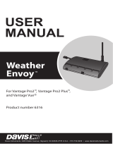
Remote Computer Installation
The illustration below shows a typical remote computer installation using a
modem. This involves connecting the data logger to the Weather Envoy and to
a modem at the station Envoy site and connecting your computer’s modem to
a phone line, which will allow you to dial the Weather Envoy.
Note: Mac Users - Refer to your WeatherLink for Mac OS X Getting Started Guide for addi-
tional installation instructions
9-Pin
Connector
(DB-9)
Optional 40' (12 m) 4-Conductor
Extension Cable and Coupler
8' (2.5 m) Cable
AC Power
Adapter
Weather Envoy
Data Logger
Weather Envoy
with Data Logger
External
Modem
25-pin Telephone Modem
Adapter (#6533)
8 feet (2.5 m)
Data Logger Cable
(standard)
Windows Computer
External or
Internal Modem

Remote Modem Connection Notes
10
Note: Before installing the Envoy and modem at a remote location, test the data logger and
connection first using a direct connection like that shown in the section above.
Remote Modem Connection Hardware Requirements
The following additional hardware is required for a phone modem connection.
• One internal or external modem connected to your computer. The modem
must be Hayes
®
–compatible and run at 1200, 2400, 4800, 9600, 14400 or
19200 baud.
• One external modem to connect to the Weather Envoy data logger. The
modem must be Hayes
®
–compatible and run at 1200, 2400, 4800, 9600,
14000 or 19200 baud.
• Telephone Modem Adapter
• The Telephone Modem Adapter (#6533) provides the connection between
the Weather Envoy data logger and the modem.
Installing with a Remote Computer
1. Install and set up an internal or external modem (according to the
instructions supplied by the manufacturer) for use with your computer.
Make a note of the COM port used by the modem. You will need this infor-
mation when entering serial port settings for the station.
2. At the Weather Envoy site, put the external modem in a location where it
can connect to both the data logger and the phone jack.
Note: Both the modem and the Weather Envoy should be powered down at this time, if they
are not already turned off.
The cable connecting the data logger to the modem is 8' (2.4 m) long. If you
need to mount the station Envoy more than 8
' from the modem, use a 40' (12
m) standard 4-conductor extension cable. Do not attempt to use more than
40
' of extension cable, or the data logger may have difficulty communicat-
ing with the modem.
3. Plug the external modem into the phone jack.
4. Connect the Weather Envoy data logger to the modem.
5. Power up the modem.
6. Power up the Weather Envoy last.
Remote Modem Connection Notes
When accessing a remote modem connection, WeatherLink automatically
dials the station and Envoy whenever an action has been performed in the soft-
ware that requires it to talk to the station.
While connected to a remote station, an On-Line icon displays in the toolbar.
This icon indicates that WeatherLink has established a connection with the
remote Envoy and weather station. Select the On-Line icon from the toolbar
or select Hang Up from the File menu to disconnect the phone connection.

Installing the Software
11
By default, WeatherLink hangs up the connection to the modem after one
minute without any communication with the station. Use the Communica-
tions Port dialog box in the Setup menu of WeatherLink to change this
default value. (See the WeatherLink help files for more information.)
Note: WeatherLink will not hang up the phone line if the Bulletin or Summary windows are
active.
Software Installation and Setup
Refer to the following procedure to install WeatherLink software on your com-
puter. The instructions below contain the base procedures for running the
WeatherLink software and setting up a connection to your Weather Envoy. All
information about the software is included as an overview. Additional setup
not featured in this manual is required for all Weather Envoy, Vantage Pro and
Vantage Pro2 consoles. See WeatherLink Online Help for complete setup
instructions.
Note: If you are installing a Davis specialized data logger (6540, 6544, 6550, 6560) please
see the included addendum for complete installation instructions.
Installing the Software
Windows Computer Using USB Connection
Follow the steps below to install the WeatherLink software.
1. Place the WeatherLink software CD in your CD ROM drive.
The install program should start automatically. If the install program does
not start, select Run from the Start menu, type D:\SETUP (or the correct
letter for your CD ROM drive), and click OK to begin the installation.
2. Follow the on-screen prompts to complete the installation.
Windows Computer Using a Serial Port Connection
1. Place the Install Disk in your CD ROM drive.
The install program should start automatically. If the install program does
not start, choose Run from the Start menu, type D:\SETUP (or E:\SETUP,
substituting the correct drive letter for D or E), and choose OK to begin the
installation.
2. Follow the on-screen prompts to complete the installation.

Running the Software
12
Macintosh Computer
1. Place the Install Disk in your CD ROM drive.
2. Copy “install.sit” from the CD to your desktop and open it.
3. The installation software will automatically extract itself.
4. Run “install”.
5. Follow the on-screen prompts to complete the installation.
Running the Software
To run the software, double-click the WeatherLink icon. If no stations have
been assigned in the program directory, the software prompts you to add a sta-
tion (see below for details). If there is more than one station in the program
directory when the application opens, the last station that was displayed is
automatically opened.
Adding a Station
1. Select New Station from the File menu. The New Station dialog displays.
2. Type the desired station name (up to 40 characters/spaces) into the Station
Name text box. The software uses the first eight characters of the station
name (not counting spaces or punctuation marks) as the name of the direc-
tory into which it saves this station’s database and configuration files. The
first eight characters of each station name must, therefore, be unique.
3. Click OK to save the new station or click Cancel to exit without saving.
The software saves the new station, creates a directory and a configuration
file for the station, and prompts you to enter the walk-through procedure.
About the Walkthrough
The software includes a station setup walkthrough that steps you through the
weather station configuration procedures. After adding a new station, the
Walkthrough dialog box automatically displays. By selecting Yes, the walk-
through process begins. By selecting No, the Walkthrough process is exited.
You can set up and configure your station by separately selecting all of the
necessary setup options from the Setup menu. A Walkthrough option is
included in the Setup menu that allows you to access the Walkthrough at any
time.
By selecting the Walkthrough process, the software displays a series of dialog
boxes. At each step in the Walkthrough process, confirmation boxes are pro-
vided to perform or skip the next step in the Walkthrough. To continue, select
OK. To skip this step and move to the next step, select Skip. To cancel the
entire walkthrough process, select Cancel.
Note: The Walkthrough, as well as all the options in the Setup menu, is the only interface for
configuring all the Weather Envoy setup options, such as Time and Date and Latitude
and Longitude settings. Please refer to the WeatherLink online help for more informa-
tion about the Walkthrough.

Running the Software
13
Communication Port Settings
WeatherLink contains a dialog box for locating the communications port
(either USB or serial) that the data logger and Weather Envoy are connected
to. Use the Communications Port dialog box to select the communications
port that is used to communicate with the Envoy.
1. Select Communications Port from the Setup menu or use the Walkthrough
to display the dialog box. The Communications Port dialog box displays.
2. Click Auto Detect. The program searches for the port that the Envoy data
logger is connected to. When the correct connection is found, the following
dialog box displays:
3. Click OK. The Communications Port dialog box displays with the correct
port selected in the Com Port drop down box.
4. Select the desired baud Rate from the Baud Rate drop down box.
19200 is the default baud rate for the Weather Envoy data logger.
5. Click OK to select the port settings and exit the dialog.
Set Alarms
You may quickly set the alarm thresholds on the Weather Envoy using the
WeatherLink software. See the Alarms section in this manual for more infor-
mation on the types of alarms available and how they work.

Running the Software
14
Note: The only way to clear an alarm in the Weather Envoy is to modify the threshold in the
Alarm Setup screen to a value that would not cause an alarm, or to delete the value
altogether.
1. Select Set Alarms from the Setup menu or press Ctrl-A.
The Set Station Alarms dialog box displays.
Enter the following information:
• High/Low Alarm - For all standard high/low alarms, enter the desired alarm
threshold into the text box. To clear an alarm, clear the contents of the text box
or enter two (2) dashes: "--".
• Barometer - Enter the 3-hour low (fall) and /or high (rise) pressure trend thresh-
olds. To clear an alarm, clear the contents of the text box or enter two (2) dashes:
"--" (two dashes).
• Time - Enter the time for the alarm in the text box. To clear the alarm, clear the
contents of the text box or enter two (2) dashes: "--".
2. When finished entering alarm information, choose Set.
The software sets the alarms on the station Envoy to match the settings in
this dialog box.
Alarms
The Weather Envoy features more than 30 alarms that can be programmed to
sound whenever a reading exceeds a set value. With the exception of baromet-
ric pressure and time, all alarms sound when a reading reaches the alarm
threshold. For example, if the high outside temperature alarm threshold is set
at 65 ºF, the alarm will sound when the temperature rises to 65.0 ºF.

Running the Software
15
Low alarms work the same way. For example, if the wind chill threshold is set
for 30 ºF, the alarm begins sounding when the temperature drops to 30.0 º and
will continue until the temperature again rises above 30.0º.
If you’re on battery power, the alarm will sound for two minutes only. If
you’re using the AC adapter, the alarm will continue as long as the condition
exists. The alarm will also sound again for each new alarm.
To silence a sounding alarm, edit the Alarm setup screen to either delete the
alarm threshold or to modify the threshold so that the current conditions don’t
cause an alarm.
Three special alarms
ET (Evapotranspiration)
ET is updated only once an hour, on the hour. If during a given hour the ET
Value exceeds the alarm threshold, the ET alarm sounds at the end of that hour.
This is true for daily, monthly, and yearly ET alarms. You must have the
optional Solar Radiation Sensor to use this alarm.
Barometric Pressure
The Weather Envoy allows you to set two barometric pressure alarms: a “rise”
alarm and a “fall” alarm. You may select any rate of change per hour between
0.01 to 0.25 in Hg (0.1 to 6.4 mm Hg, 0.1 to 8.5 hPa/mb); the alarm will sound
if the rate of change (in the selected direction) exceeds the threshold you set.
Time
The time alarm is a standard “alarm clock”. It sounds at the set tim. Make sure
you choose AM or PM, if you’re in 12-hour mode. It sounds for one minute.
Auto Download
You may set up the software to automatically download data at specified times
each day (the software must be running and a constant connection to the data
logger in the Envoy must be made).
1. Select Auto Download from the Setup menu or press Ctrl-J.

Running the Software
16
The Auto Download dialog box appears. The stations which appear in the
Auto Download List will be downloaded automatically.
2. To add a station to the Auto Download List, double-click on the station
name or select the station from the Station Names list and click Add.
The station name moves to the Auto Download List. You may select more
than one station before clicking Add to add several stations at once. You
may quickly add all stations in the Station Names list by clicking Add All.
3. To remove a station from the Auto Download List, select the station and
click Remove.
The station name removes from the Auto Download List. You may select
more than one station before clicking Remove to remove several stations at
once. You may quickly remove all stations in the list by choosing Clear.
4. To set the time(s) at which the selected station should be downloaded,
choose Download At.

Weather Data Measured & Calculated
17
The Download At dialog box appears.
5. Enter the following information:
• Download Times - Select the hour(s) at which the software should automati-
cally download information from this station by clicking on the desired hour in
the list. You may select as many download hours as you want; the software will
download data from your station during each of the specified hours. To de-select
a previously selected hour, click on it again. To quickly select all hours, choose
Choose All. To quickly clear all selected hours, choose Clear.
• Offset Time - To force the software to automatically download a specific num-
ber of minutes after the selected hour(s), enter the number of minutes here. For
example, in the illustration above the software would automatically download at
8:05 and 9:05 am.
6. After setting the download time(s), click OK.
The software saves the automatic download time settings.
Weather Data Measured & Calculated
This section outlines each of the weather conditions measured and/or calcu-
lated by the Weather Envoy, by the Vantage Pro Integrated Sensor Suite (ISS),
and by optional Vantage Pro sensors. Each section includes a brief discussion
of the weather condition and a listing of the various ways in which the unit dis-
plays or stores that condition. Be aware that some of the weather conditions
require an optional sensor in order to measure or calculate a value.

Weather Data Measured & Calculated
18
Wind
The anemometer measures wind speed and wind direction.
Temperature
The Weather Envoy uses the ISS temperature sensor to measure the outside air
temperature. A second temperature sensor in the Weather Envoy measures the
inside air temperature. Additional temperature sensors (available only with
wireless Vantage Pro and Weather Envoy systems) can be used to measure
temperature in other locations. You may use these extra sensors to measure
any other temperatures that are within the sensor’s range, including liquids
such as water.
Apparent Temperatures
The Weather Envoy calculates three apparent temperature readings: wind
chill, heat index, and the temperature/humidity/wind index (THW Index).
Wind chill
Wind chill takes into account how the speed of the wind affects our perception
of the air temperature. Our bodies warm the surrounding air molecules by
transferring heat from the skin. If there’s no air movement, this insulating
layer of warm air molecules stays next to the body and offers some protection
from cooler air molecules. However, wind sweeps that warm air surrounding
the body away. The faster the wind blows, the faster heat is carried away and
the colder you feel.
Wind chill is not stored in archive memory. Wind chill is calculated whenever
it is displayed. Editing temperature or wind speed values changes the wind
chill value.
Note: WeatherLink versions 5.1 and later use the Osczevski (1995) equation to calculate
wind chill. This is the adopted method used by the US National Weather Service.
Heat Index
The Heat Index uses the temperature and the relative humidity to determine
how hot the air actually “feels.” When humidity is low, the apparent tempera-
ture will be lower than the air temperature, since perspiration evaporates rap-
idly to cool the body. However, when humidity is high (i.e., the air is saturated
with water vapor) the apparent temperature “feels” higher than the actual air
temperature, because perspiration evaporates more slowly.
THW (Temperature - Humidity - Wind)
The THW Index uses humidity and temperature to calculate an apparent tem-
perature, but includes the cooling and heating effects of wind on our percep-
tion of temperature.
THSW (Temperature - Humidity - Solar - Wind)
The THSW Index uses humidity and temperature to calculate an apparent tem-
perature, including the cooling and heating effects of both and solar radiation
/