Grizzly M1022 Owner's manual

Category
Lathes
Type
Owner's manual

Grizzly M1022 is a taper attachment specifically designed for use with the Grizzly M1019 Gear Head Lathe. It enables accurate taper production up to 12 inches without repositioning. The attachment features scales reading inches-per-foot and degrees, along with an angle adjusting screw for precise taper control. Additionally, it offers the convenience of being operable without disengaging the locking nut, allowing for quick adjustments.

Grizzly M1022 is a taper attachment specifically designed for use with the Grizzly M1019 Gear Head Lathe. It enables accurate taper production up to 12 inches without repositioning. The attachment features scales reading inches-per-foot and degrees, along with an angle adjusting screw for precise taper control. Additionally, it offers the convenience of being operable without disengaging the locking nut, allowing for quick adjustments.

INSTRUCTION MANUAL
MODEL M1022
TAPER ATTACHMENT
FOR USE WITH MODEL M1019
Phone: (360) 734-3482 On-Line Technical Support: tech-support@shopfox.biz
COPYRIGHT © DECEMBER, 2004 BY WOODSTOCK INTERNATIONAL, INC.
WARNING: NO PORTION OF THIS MANUAL MAY BE REPRODUCED IN ANY SHAPE OR FORM WITHOUT
THE WRITTEN APPROVAL OF WOODSTOCK INTERNATIONAL, INC.
Printed in China
#6809BL
-2-
-3-
M1022 Taper Attachment
NOTICE
When ordering replacement parts, refer
to the parts list and diagram in the back
of the manual.
The following is a description of the main components
shipped with the
SHOP FOX
®
Model M1022 Taper
Attachment. Lay the components out to inventory them.
Box Contents (Figure
1)
QTY
A. Taper Attachment Body ..................................1
B. Clamping Block ............................................1
C. Support Rod ................................................1
D. Vertical Rod with Cap Screw M6 x 1.0-16 .............1
E. Cap Screws M8-1.25 x 30 ................................4
F. Cap Screw M6-1.0 x 20 ...................................1
G. Roll Pins .....................................................2
H. Washers 8mm ..............................................4
I. Washer 17mm ..............................................1
If any parts appear to be missing, examine the packag
-
ing carefully to be sure those parts are not among the
packing materials. If any parts are missing, find the
part number in the back of this manual and contact
Woodstock International, Inc. at (360) 734-3482 or at
INVENTORY
Figure 1. Main contents.
A
B
G
C
D
H
F
I
E
SUFFOCATION
HAZARD!
Immediately
discard
all plastic bags and
packing materials to
eliminate choking/suf-
focation hazards for
children and animals.
-4-
M1022 Taper Attachment
INSTALLATION
Figure 2. Back of lathe with splash guard
removed.
Installing the Taper
Attachment
To install the taper attachment, do these steps:
1. Disconnect the lathe from its power source!
2. Remove the splash guard from the back of the lathe
(Figure 2). If the lathe must be moved to allow
access to the splash guard, consult the lathe manual
for safe moving information.
Note
: If you move the lathe, be sure to re-level it
after returning the lathe to its final location.
3. Remove the locking nut that holds the bearings and
spacers in place at the end of the cross slide lead
screw (Figures 2 &
3). You may need to bend one or
more tangs of the external tooth washer to accom
-
plish this.
Figure 3. Cross lead screw components on
lathe.
MAKE your shop child
safe.Ensure that your
workplace is inacces
-
sible to youngsters by
closing and locking all
entrances when you
are away. NEVER allow
untrained visitors in
your shop when assem
-
bling, adjusting or
operating equipment.
The Model M1022 Taper Attachment mounts quickly to
the back of the carriage and bed way of the Model M1019
Gear Head Lathe. Accurate tapers up to 12" can be pro
-
duced without repositioning the attachment. The Model
M1022 features scales at both ends, reading inches-per-
foot and degrees. An angle adjusting screw with fine
threads achieves exacting control when setting tapers.
Another feature is the ability to use it without disengaging
the locking nut. This will allow it to be functional at any
time by simply tightening the clamping block.
The Model M1022 comes carefully packaged and coated
with grease for rust protection. You will need to clean all
pieces thoroughly with a solvent cleaner prior to instal
-
lation and use. For optimum performance from your
taper attachment, make sure you clean all moving
parts or sliding contact surfaces that are coated. Avoid
chlorine-based solvents as they may damage painted
surfaces should they come in contact. Always follow the
manufacturers instructions when using any type of clean
-
ing product.
Bearing
Housing
Lead
Screw
Bearing Dust
Cover
Thrust
Bearings
External Tooth
Washer
Locking Nut
Cross Slide Lead Screw
Spacer
-5-
M1022 Taper Attachment
4. Remove the spacer, bearing dust cover, and thrust
bearing (
Figure 6) from the end of the lead screw.
5. Remove the two cap screws securing the bearing
housing, along with the housing. Leave the remain
-
ing thrust bearing on the lead screw (
Figure 6).
6. Remove the six Phillips head screws from the top
cover plate (
Figure 4) of the taper attachment body.
Set the screws and cover aside for later use.
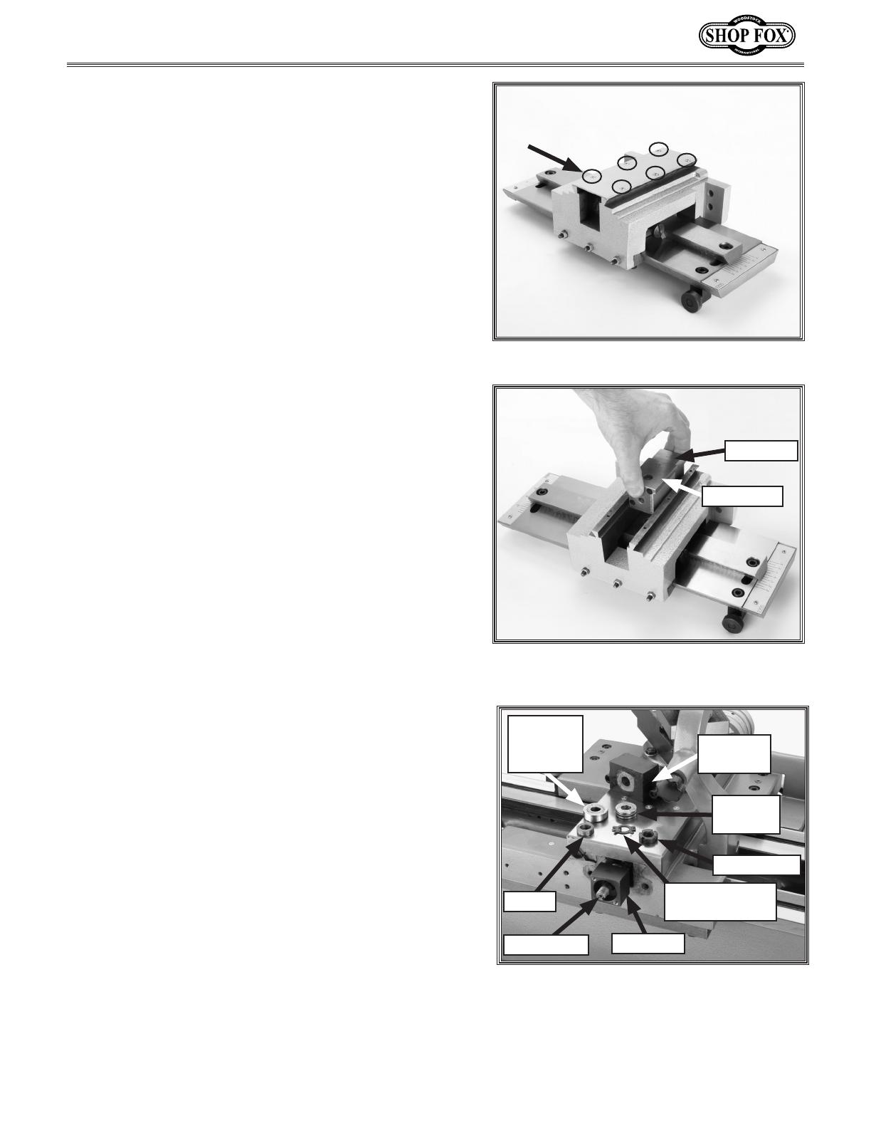
7. Remove the end block and slide block from the taper
attachment body by pulling up, as shown in
Figure 5.
These blocks are connected by two cap screws.
Note: The slide block is loosely pinned to a portion of
the cross
slide. Be careful not to lose the pin. Set it
aside for future installation or keep the
pin in place.
8. Separate the end block and slide block by removing
the two cap screws in the slide block. Set the slide
block and cap screws aside for
Step 13.
9. Slide the end block over the lead screw. The end
block bearing pocket and the threaded holes must
face outwards, as shown in
Figure 6.
10. Install the thrust bearing, spacer, and external tooth
washer in the same order they were removed into
the opening in the end block. Save the bearing dust
cover in case you want to remove the taper attach
-
ment.
11. Thread the locking nut (Figure 6) onto the end of
the lead screw and tighten the nut while holding the
cross slide handwheel
. Do not over-tighten the lock-
ing nut. To check, turn the end block. Only a small
amount of resistance should be felt. Adjust the lock-
ing nut as needed.
12. Hold the locking nut in place and bend one or more
tangs of the external tooth washer over the nut.
13. Connect the slide block to the end block using the
two cap screws that were removed in Step 8. The end
block may need to be rotated to line up the holes
.
Figure 4. Head screws on cover plate.
Figure 5. End block and slide block removed
from taper attachment body.
Figure 6. Lead screw component
identification.
Bearing
Dust
Cover
Thrust
Bearing
Lead Screw
Bearing
Housing
End Block
External Tooth
Washer
Locking Nut
Spacer
End Block
Slide Block
-6-
M1022 Taper Attachment
Figure 7. Slide block assembly.
Mounting Taper
Attachment Body
The taper attachment is heavy and could cause seri-
ous injury if it drops on you. To minimize this pos
-
sibility, have an assistant hold the taper attachment
body while it is being attached to the lathe
.
To mount the taper attachment, do these steps:
1. Remove any paint or debris from the four threaded
holes (
Figure 7) on the rear of the lathe carriage
and from the corresponding holes on the taper
attachment. Debris could cause the mounting screws
to not screw in completely.
2. With the help of an assistant, align the the four
holes on the taper attachment body with the thread
-
ed holes on the lathe carriage. Use the four M8-1.25
x 30 cap screws to loosely fasten the taper attach
-
ment body to the lathe. A long-handled, ball end, 6
mm hex wrench works best for this step.
Note:
If you are only able to use two of the holes after
Step 2, you will need to use the two roll pins included
with the taper attachment. To do this you will need
to drill holes through the main body and into the c
ar-
riage. Use a #9 or a 5 mm drill bit. Be sure not to
drill any deeper tha
n 5/8" into the carriage. Once the
holes are drilled, clean out any debris and insert the
roll pins.
Threaded Holes
Slide Block
-7-
M1022 Taper Attachment
Figure 8. Taper attachment body mounted
onto lathe.
Cross Slide
Main Slide
Taper Bar
Taper Bar Slide
Slide Block
3. With the taper attachment body loosely fastened (see
Figure 8), move the slide block back and forth, by
either pulling or pushing on the lead screw or turning
the cross slide handwheel. Stop when the pin in the
slide block can be inserted into the hole in the taper
bar slide. Push the pin into place to secure the slide
block (see Step 7 on Page 5).
Note: The dovetail ways of the cross slide must clear
the top of the taper attachment and line up with the
dovetails on the taper attachment. The mounting
holes in the taper attachment are oversized to allow
for minor height adjustments.
4. Adjust the taper attachment for clearance and check
that the cross slide moves in and out, along its full
range of motion, without increased resistance. When
the cross slide moves unobstructed and smoothly,
tighten the mounting screws.
5. Reassemble the top cover plate, using the six Phillips
head screws to fasten it together.
-8-
M1022 Taper Attachment
Figure 9. Clamping block components.
Figure 10. Support rod and clamping
block installed onto taper attachment.
Clamping Block Installation
The clamping block is composed of a solid cast clamping
bracket and a loose clamping jaw. The bracket has two
holes for clamping screws that attach the clamping jaw
(Figure 9). It also has a lip that must extend beyond the
flat surface of the bed way.
To attach the clamping block, do these steps:
1. Loosen clamping screws on the clamping bracket and
place the clamping bracket over the bed way.
2. Tighten the clamping screws.
3. Adjust the two leveling setscrews on the clamping
jaw until clamping surfaces on the clamping jaw
and the bottom of the bed way are parallel when
the clamping screws are tight. If these surfaces are
not parallel, loosen the clamping screws and adjust
them as needed.
4. Insert the end of the support rod through a hole in
the vertical rod. Tighten the cap screw on the verti
-
cal rod.
5. Insert the vertical rod into the hole in the clamping
bracket, making sure the top of the rod is flush with
the top of the clamping bracket, and secure the rod
with an M6-1 x 16 cap screw.
6. Position the support rod, as shown in Figure 10, and
secure the rod to the bottom of the taper attach
-
ment body with the M6-1 x 20 cap screw.
7. Adjust the position of the vertical rod until the sup-
port rod is parallel with the lathe bed, and tighten
the cap screws on the clamping block and bottom of
the taper attachment
.
Note: Position the clamping block as close to the
main body as possible for the best stability
.
8. Re-attach the splash guard to the lathe and reposi-
tion the lathe as needed.
Clamping
Bracket
Bed
Way
Clamping Jaw
Support Rod
Clamping Block
Clamping
Screw
Leveling
Setscrew
Vertical Rod
-9-
M1022 Taper Attachment
OPERATIONS
Angle Adjustments
The taper angle is adjusted by loosening the two cap
screws at the ends of the taper bar and pivoting the
taper bar on the center pin. The angle adjusting knob
allows for fine control of the angle (Figure
11).
There are two scales, one at each end of the main body.
One is labeled for degrees and the other is labeled for
inches-per-foot (I.P.F). Either of these scales will allow
you to get close to the desired taper, but finer adjust
-
ments should be made with an indicator and test bar.
Once the desired setting is reached, tighten the two cap
screws. Double check the setting to ensure accuracy.
Always wear safety glasses when oper-
ating the lathe. Failure to comply may
result in serious personal injury.
DO NOT investigate problems or adjust
the lathe while it is running. Wait until
the machine is turned off, unplugged
and all working parts have come to a
complete stop before proceeding!
To use the taper attachment, tighten the clamping screws
on the clamping block to secure it to the lathe bed. When
not in use, loosen the clamping screws. Removal of the
clamping block or the taper attachment is not necessary
when changing from taper turning to straight turning.
Clamping Block
Adjustments
Figure 11. Taper attachment adjustments.
Cap Screws on
Taper Bar
Bottom
Gib
Screws
Angle
Adjusting Knob
-10-
M1022 Taper Attachment
The bottom gib is mounted on the back inside edge of the
main body casting. Three M6 hex screws (Figure 12) hold
it in place and are secured with nuts. If the gib is too
loose, finish problems will occur. If the gib is too tight,
the main slide will not move smoothly.
To adjust the bottom gib, do these steps:
1. Loosen the three nuts and apply tension evenly to
the three setscrews. Use only moderate pressure
when tightening these setscrews. They should be
tight enough to keep the main slide from rocking in
the main body casting. Check by rocking the main
slide by hand.
2. When satisfied with your results, tighten the nuts
while maintaining the setscrew position. Double
check the main slide to ensure that it moves smooth
-
ly. Re-adjust if necessary.
3. Re-attach the support rod to the taper attachment
body.
Bottom Gib Adjustments
Top Gib Adjustments
The top gib (see Figure 12) is mounted to a taper slide
that moves along the taper bar on the taper attachment.
The taper slide maintains the motion of the cross slide
to produce the taper. If the gib is too loose, the angle
can be affected and the finish will suffer. If the gib is too
tight, the slide will not move freely.
To adjust the top gib, do these steps:
1. Remove the cap screw that holds the support rod to
the taper attachment body.
2. Adjust the taper bar angle to zero.
3. To tighten the gib, loosen the gib screw on the left
side of the taper slide (as viewed from the front of
the lathe) and tighten the right screw. To loosen
the gib, loosen the right screw and tighten the left
screw. When adjustments are complete, tighten the
loose gib screws so the gib doesn't move.
4. The gib is properly adjusted when the taper slide
can be moved by hand with moderate force.
Note: Do not replace the support rod at this time.
Figure 12. Gibs and gib screws.
Top Gib Screw
Bottom Gib Screws
Bottom Gib
Top Gib
-11-
M1022 Taper Attachment
PARTS





































-12-
M1022 Taper Attachment
Parts List
REF PART # DESCRIPTION REF PART # DESCRIPTION
1 XPSB02M CAP SCREW M6-1 X 20 24 XM1022024 GIB
2 XPSB45M CAP SCREW M8-1.25 X 45 25 XM1022025 SLIDE
3 XM1022003 CLAMPING PLATE 26 XM1022026 ADJUSTING BLOCK
4 XPSS11M SET SCREW M6-1 X 16 27 XPSB06M CAP SCREW M6-1 X 25
5 XPSB01M CAP SCREW M6-1 X 16 28 XM1022028 SLANT IRON
6 XM1022006 BRACKET 29 XPN01M HEX NUT M6-1
7 XPSB01M CAP SCREW M6-1 X 16 30 XPSS25M SET SCREW M6-1 X 20
8 XM1022008 VERTICAL ROD 31 XM1022031 COVER
9 XM1022009 SUPPORTING ROD 32 XPS07M PHLP HD SCR M4-.7 X 8
10 XM1022010 SIGN PLATE 33 XPSB13M CAP SCREW M8-1.25 X 30
11 XPS79M PHLP HD SCR M3-.5 X 8 34 XM1022034 PIN 5 X 25
12 XPSB13M CAP SCREW M8-1.25 X 30 35 XPW01M FLAT WASHER 8MM
13 XM1022013 COPYING PLATE 36 XM1022036 MAIN BRACKET
14 XM1022014 POSITIONING SCREW 37 XPSB108M CAP SCREW M5-.8 X 45
15 XPSB13M CAP SCREW M8-1.25 X 30 38 XPSS16M SET SCREW M8-1.25 X 10
16 XM1022016 MOVING BLOCK 39 XM1022039 PIN 12 X 50
17 XM1022017 COPYING MODE 40 XM1022040 SLIDE BLOCK
18 XM1022018 SIGN PLATE 41 XM1022041 END BLOCK
19 XM1022019 PIN 3 X 18 42 XPLN09 LOCKING NUT M12-1.25
20 XM1022020 HANDLE 43 XPTLW12M EXT TOOTH WASHER M12
21 XM1022021 SUPPORTING BLOCK 44 XM1022044 SPACER M12 X 8
22 XM1022022 THREADED ROD 45 XP51101 THRUST BEARING 51101
23 XM1022023 ROUND NUT
Warranty
Woodstock International, Inc. warrants all SHOP FOX
®
machinery to be free of defects from workmanship and
materials for a period of two years from the date of original purchase by the original owner. This warranty does
not apply to defects due directly or indirectly to misuse, abuse, negligence or accidents, lack of maintenance, or
reimbursement of third party expenses incurred.
Woodstock International, Inc. will repair or replace, at its expense and at its option, the
SHOP FOX
®
machine or
machine part which in normal use has proven to be defective, provided that the original owner returns the prod
-
uct prepaid to the
SHOP FOX
®
factory service center or authorized repair facility designated by our Bellingham,
WA office, with proof of their purchase of the product within two years, and provides Woodstock International,
Inc. reasonable opportunity to verify the alleged defect through inspection. If it is determined there is no defect,
or that the defect resulted from causes not within the scope of Woodstock International Inc.'s warranty, then the
original owner must bear the cost of storing and returning the product.
This is Woodstock International, Inc.'s sole written warranty and any and all warranties that may be implied by
law, including any merchantability or fitness, for any particular purpose, are hereby limited to the duration of
this written warranty. We do not warrant that
SHOP FOX
®
machinery complies with the provisions of any law or
acts. In no event shall Woodstock International, Inc.'s liability under this warranty exceed the purchase price paid
for the product, and any legal actions brought against Woodstock International, Inc. shall be tried in the State of
Washington, County of Whatcom. We shall in no event be liable for death, injuries to persons or property or for
incidental, contingent, special or consequential damages arising from the use of our products.
Every effort has been made to ensure that all
SHOP FOX
®
machinery meets high quality and durability stan-
dards. We reserve the right to change specifications at any time because of our commitment to continuously
improve the quality of our products.
  • Page 1 1
  • Page 2 2
  • Page 3 3
  • Page 4 4
  • Page 5 5
  • Page 6 6
  • Page 7 7
  • Page 8 8
  • Page 9 9
  • Page 10 10
  • Page 11 11
  • Page 12 12
  • Page 13 13
  • Page 14 14
  • Page 15 15
  • Page 16 16

Grizzly M1022 Owner's manual

Category
Lathes
Type
Owner's manual

Grizzly M1022 is a taper attachment specifically designed for use with the Grizzly M1019 Gear Head Lathe. It enables accurate taper production up to 12 inches without repositioning. The attachment features scales reading inches-per-foot and degrees, along with an angle adjusting screw for precise taper control. Additionally, it offers the convenience of being operable without disengaging the locking nut, allowing for quick adjustments.

Ask a question and I''ll find the answer in the document

Finding information in a document is now easier with AI