Page is loading ...

www.gemeasurement.com
BHGE Data Classification: Public
Druck PV 212
Hydraulic Hand-pump
Instruction Manual
English 1 - 8
Deutsch 9 - 16
Español 17 - 24
Français 25 - 32
Italiano 33 - 40
Português 41 - 48
Русский 49 - 56
Иކ
57 - 62
মୁ
63 - 70

© 2005 Baker Hughes, a GE company – All rights reserved. PV 212 Instruction Manual-English | i
1
2
8
10
7
9
3
4
6
5
11
1/4”
#1

ii | PV 212 Instruction Manual-English © 2005 Baker Hughes, a GE company – All rights reserved.

© 2005 Baker Hughes, a GE company – All rights reserved. PV 212 Instruction Manual-English | 1
Introduction
This manual provides operating instructions for the PV 212 hydraulic hand-pump.
Safety
The manufacturer has designed this equipment to be safe when operated using the
procedures detailed in this manual. The user must not use this equipment for any other
purpose than that stated.
This manual contains safety and operating instructions that must be followed to make sure of
safe operation and to keep the equipment in a safe condition. The safety instructions are
either warnings or cautions issued to protect the user and the equipment from injury or
damage.
Use suitably qualified technicians
*
and good engineering practice for all procedures in this
manual.
Pressure
Do not apply pressure greater than the maximum safe working pressure stated in the
specification.
Toxic Materials
There are no known toxic materials used in construction of this equipment.
Maintenance
The equipment must be maintained using the procedures in this publication. Further
manufacturer’s procedures should be done by an authorized service agents or the
manufacturer’s service departments.
Technical Advice
For technical advice contact the manufacturer or subsidiary.
* A qualified technician must have the necessary technical knowledge, documentation, special test
equipment and tools to carry out the required work on this equipment.

2 | PV 212 Instruction Manual-English © 2005 Baker Hughes, a GE company – All rights reserved.
Symbols
The following symbols mark this equipment:
Abbreviations
The following abbreviations are used in this publication.
Note: Abbreviations are the same in the singular and plural.
1. Introduction
The PV 212 is a portable source of hydraulic pressure. Each pump includes a reservoir, and a
volume control for fine adjustment. To prevent damage to sensitive instruments, there are
five pressure relief valves available for different pressure ranges.
Symbol Description
This symbol, on the equipment, indicates a warning and that the user should refer to the
user manual.
Ce symbole, sur l'appareil, est un avertissement qui indique que l'utilisateur doit
consulter le manuel d'utilisation.
Do not dispose of this product as household waste. Use an approved organization that
collects and/or recycles waste electrical and electronic equipment. For more information,
contact one of these:
- Our customer service department: www.gemeasurement.com
- Your local government office.
Abbreviation Description
°C degrees Celsius
BSP British Standard Pipe thread
COSHH Control of Substances Hazardous to Health regulations
°F degrees Fahrenheit
lb pounds
kg kilogram
mm millimetre
MSDS Material Safety Data Sheet
NPT National Pipe Thread
psi pounds per square inch
PTFE polytetrafluoroethylene

© 2005 Baker Hughes, a GE company – All rights reserved. PV 212 Instruction Manual-English | 3
2. Operation
Note: Wherever possible, use o-ring seals in the BSP connection ports this is the
recommended method of sealing.
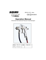
Key to Figure #1
1. Pressure release valve.
2. Fine adjust vernier.
3. Prime/High pressure selector.
4. Scissor handles.
5. Reservoir.
6. Fluid inlet tube.
7. Reservoir fill plug.
8. Output port.
9. Output port.
10. Rear port for an optional pressure relief valve. Do not use for other functions.
11. Recommended fluid level.
2.1 Connecting the Pump
BSP ports can be fitted with any suitable length ¼ BSP male connector, sealing either with an
o-ring at the bottom of the port or a bonded seal at the top. Adaptors are supplied to convert
the BSP ports to ¼ NPT. Fit a suitable blanking plug to an unused port.
2.2 Pressure Release Valve (Figure #1)
Use this (1) to reduce or release the pressure in the system. The amount of turn sets the rate
to release the pressure. Only minimum force is necessary to seal the system.
WARNING Before applying pressure, make sure all connections are
correct and equipment is internally clean and free from damage.
Make sure that all equipment is to the correct pressure rating.
Do not exceed the maximum operating pressure stated in the specification.
Observe the relevant health and safety precautions.
CAUTION If PTFE tape is used to seal NPT threads, ensure that only a
sufficient amount is used to achieve pressure seal. If excess tape is used,
particles can become loose during the connector mating process and enter
the pump, potentially leading to loss of pump performance or pressure
leaks.

4 | PV 212 Instruction Manual-English © 2005 Baker Hughes, a GE company – All rights reserved.
2.3 Fine Adjust Vernier (Figure #1)
To make accurate adjustments to the pressure, turn the fine adjust vernier (2) clockwise to
increase the pressure or counterclockwise to decrease the pressure.
3. Operation
1. Remove the reservoir fill plug (7), fill the reservoir (5) to the indicated level (11), and
replace the fill plug.
2. Connect a reference instrument to connection (8).
Note: Use PTFE tape or appropriate sealant to seal all NPT connections. Do not
use PTFE tape on parallel threads. If PTFE tape is used to seal NPT threads, ensure
that only a sufficient amount is used to achieve pressure seal. If excess tape is
used, particles can become loose during the connector mating process and enter
the pump, potentially leading to loss of pump performance or pressure leaks.
3. Connect the instrument under test to connection (9). Use pressure-rated flexible
hose or use the optional accessories to direct mount it.
4. Set the fine adjust vernier (2) to the midpoint of its travel. Turn it fully clockwise, then
four to six turns counterclockwise.
5. Open the pressure release valve (1). Turn it fully clockwise and then one turn
counterclockwise.
6. Squeeze the scissor handles (4) fully together and turn the selector (3) to the “Prime”
position.
7. Remove trapped air from the pump by squeezing the scissor handles (4) several
times. Make sure that the fluid inlet tube (6) remains immersed in fluid at all times.
8. Close the pressure release valve (1) by turning it fully clockwise, and tighten to seal.
9. To prime the system, squeeze the scissor handles (4) together and then release them
to get the fluid into the pump cylinder. Repeat this operation until the system is fully
INFORMATION To prevent damage, DO NOT use force to turn the fine
adjust vernier (2).
WARNING Uncontrolled release of high pressure is dangerous and may
cause damage to equipment. Because the internal pressure can get very
high during operation, make sure that all the connections are made
correctly.
DO NOT ignore the maximum operating pressure specified on the pump
label.
Before you connect a pressure component to the PV 212, make sure that it
is isolated from the pressure supply and release the internal pressure
slowly. DO NOT connect the pump to an external pressure source.

© 2005 Baker Hughes, a GE company – All rights reserved. PV 212 Instruction Manual-English | 5
primed, as indicated by pressure build-up on the reference instrument or the
instrument under test.
10. With the scissor handles (4) fully together, turn the selector (3) to the “High” position.
Operate the scissor handles (4) until the pressure is almost correct.
Note: At higher pressures, it is easier to use short handle strokes.
11. To adjust the pressure to the correct value, turn the fine adjust vernier (2) clockwise
to increase the pressure or counterclockwise to decrease the pressure.
Note: Initially, small pressure changes can occur (thermodynamic effects, the
seals settle, the hoses expand). The pressure will stabilize after a short time.
12. To fully release the pressure from the system, slowly turn the pressure release
valve (1) counterclockwise one full turn. This completes the procedure.
Note: Careful operation of the pressure release valve (1) gives a controlled release
of pressure.
4. Fault Finding
1. If the system appears to lose pressure, repeat the above procedure. Make sure: there
is no damage to the seals, the adapters are tightened sufficiently, the pressure
release valve (1) is tightened sufficiently to seal.
2. Check the optional pressure release valve (10) setting, if fitted.
3. When in operation, if the fluid level in the reservoir falls by a large amount, this can
create a partial vacuum and affect pump performance. To prevent this, loosen the fill
plug (7) and let air into the reservoir.
4. If the PV 212 has not been used for a period of time, it may be difficult to operate on
the first stroke. It will become free after this.
5. For seal replacement refer to the service kit instructions.
If, for any reason, a fault occurs within the pump, it is recommended that the equipment be
returned to an appointed agent.

6 | PV 212 Instruction Manual-English © 2005 Baker Hughes, a GE company – All rights reserved.
5. General Specification
6. Returned Goods Procedure
If the unit requires calibration or is unserviceable, return it to the nearest GE Service Centre
listed at: www.gemeasurement.com
Contact the Service Department to obtain a Return Authorization (Worldwide excluding
USA).
In the USA, obtain a Return Material Authorization [RMA].
Provide the following information on either a RGA or RMA:
• Product (i.e. PV 212)
• Serial number
• Details of defect/work to be undertaken
• Operating conditions
6.1 Safety Precautions
You must inform GE if the product has been in contact with any hazardous or toxic substance.
The relevant COSHH or in the USA, MSDS, references and precautions to be taken when
handling.
INFORMATION Hydraulic fluids must be compatible with stainless
steel, anodized aluminum, nitrile rubber, PTFE, polypropylene, Delrin,
acrylic and nylon.
Item Specification
Hydraulic Pressure Range PV 212-22: 0 to 700 bar (0 to 10,000 psi)
PV 212-23: 0 to 1000 bar (0 to 15,000 psi)
Pressure Connections ¼” BSP parallel female
Recommended Hydraulic Fluids De-mineralized water or low viscosity mineral-based
hydraulic oil.
Dimensions (Length x Width x Depth) 230 mm (9.0”) x 160 mm (6.25”) x 70 mm (2.75”)
Weight (approximate) 1.45 kg (3.2 lb)
INFORMATION Service by unauthorized sources will affect the
warranty and may not guarantee further performance.

© 2005 Baker Hughes, a GE company – All rights reserved. PV 212 Instruction Manual-English | 7
6.2 Approved Service Agents
For the list of service centers:
www.gemeasurement.com

8 | PV 212 Instruction Manual-English © 2005 Baker Hughes, a GE company – All rights reserved.

16 | PV212 Bedienungsanleitung-Deutsch © 2005 Baker Hughes, a GE Company – Alle Rechte vorbehalten.

24 | Manual de instrucciones PV 212-Español © 2005 Baker Hughes, a GE Company – Reservados todos los derechos.

32 | PV 212 Notice d'emploi-Français © 2005 Baker Hughes, a GE Company – Tous droits réservés.

40 | PV 212 Manuale d’uso-Italiano © 2005 Baker Hughes, a GE company – Tutti i diritti riservati.

56 | Руководство по эксплуатации PV212. Русский © Baker Hughes, a GE company, 2005. Все права защищены.

© 2005 Baker Hughes, a GE Company – ґऊ۱߄ߓӯ澞 PV 212 ݱҁ۴ӆ - Иކ | 61
12. О؏ҶୋݹԹԃۣͫଢޞޔԹԃୋݹஂ (1) ▲ޅ֥澞߽ؼ؏ۨд
ӕ澞
ࡉଚ : شڶݱҁԹԃୋݹஂ (1)ͫљؘ࣫ԹԃՉݏୋݹ澞
4. ݻஞ߲
1. ײߧरѷԹԃѺͫө୍זЇଚଋ३澞ेґإدўߌְ݃澝ଠ֘ҭӣ
㝲ব澝Թԃୋݹஂ (1) ҭӣ㝲বљґચإد澞
2. ࠒ߲ՕଣԹԃୋݹஂ (10) ગ ͧײٝ؍ͨ澞
3. ֨ݱҁଋ३Иͫײߧҥ䃠য়ङ䃠ѹםٱЈͫөѫфࣿୂӣऱॱͫڧր䀿ङ
ۅਈ澞Оஅ࠲ӟ࣫࠴ەӑͫબߠԈҭ (7)ͫએॱࡈҵҥ䃠য়澞
4. ײߧ▲࠼ޞӄߌ҅ऀ PV 212ͫআ▲੧३ИङݱҁՕਈࡁૻ֟澞࠴եرՊڱ
ி࢝澞
5. ثйإدў݅ͫબՀৰ߆ԇўݱҁપޢ澞
ײߧ֜ѠѾԽ֜ͫ䀿ӄӟ࣫ݻஞͫڏઑرગוଟ֛ܶؔїࣲה澞
5. ▲ਢઁࠀ
ґ㔴 䃎Ը䃎ڶஏЉЈ敕ଥ澝୕߃ࣔ斂支澝▂勮ࠉ澝 PTFE澝ো▏䏥澝ো䟣
戆ߚ劮澝勮傰ոؾӂ؟澞
ࣹ ߡ
䃠Թਸ֠ PV 212-220 ӱ 700 bar ͧ0 ӱ 10,000 psiͨ
PV 212-230 ӱ 1000 bar ͧ0 ӱ 15,000 psiͨ
Թԃݎף ¼” BSP ٵ੧࠾ݎף
ݐ਼ङ䃠Թ䃠 ԗࡊ۪Ѻ溒چ䩳࣒澞
ؾت ͧ x ء x ࢋͨ
230 mm (9.0”) x 160 mm (6.25”) x 70 mm (2.75”)
୍ ͧםͨ
1.45 kg (3.2 lb)

62 | PV 212 ݱҁ۴ӆ - Иކ © 2005 Baker Hughes, a GE Company – ґऊ۱߄ߓӯ澞
6. ଞૄ३پ
ײߧગוӕ۪ৱޗࡣғͫબرҿଏଟਙљЈৠ֭Їӧӟङ߂ GE ߆ԇИڶ
www.gemeasurement.com
Њ߆ԇୂ৻љੂڱଞૄ݉ߓ ͧ২֢љיङҶࣱ՟֪ͨ澞
২֢ऀۯݎՉଞމؙ߲ [RMA]澞
ݕ҈Ҽй RGA ۪ RMA ङЈӧҒێ
• фս ͧԯ PV 212ͨ
• پӧ՚
• ߄Ҽ / ۼ੧ङٗҁङદূપޢ
• ݱҁߚў
6.1 ؍Ҷஅݒޑ
ײߧфսݎઇଋѠѾԮக۪߄ࡀ࣒ૅͫબԇڷପऽ GE澞
ݱҁޞͫબՀஃबҼ 澦߄؞࣒ૅ҅ऀࣲઁؔ澧 (COSHH) ͧ২֢О 澦ԗ؆ս؍Ҷރ݇પ
ޢа澧 (MSDS)ͨٷՈஅݒޑ澞
6.2 ઍՕङ߆ԇїࣲ
߄Ҽ߆ԇИڶङӧ੮ͫબઘ
www.gemeasurement.com
ґ㔴 ࣒ޭܪъճঢ۵ذѪڦտҐҒͧЋՔৗݸࡄҐ੩ૡ▁ࣩࠖ㓬ৗ澞

© 2005 Baker Hughes, a GE company – ↓᩿㌿㍕ࢆ⚗ࡎࡿࠋ PV 212 ྲྀᢅㄝ᫂᭩ - ᪥ᮏㄒ | 69
6.2 ㄆᐃࢧ࣮ࣅࢫ௦⌮ᗑ
ࢧ࣮ࣅࢫࢭࣥࢱ࣮ࡢࣜࢫࢺࡘ࠸࡚ࡣࠊḟࢆཧ↷ࡋ࡚ࡃࡔࡉ࠸ࠋ
www.gemeasurement.com

70 | PV 212 ྲྀᢅㄝ᫂᭩ - ᪥ᮏㄒ © 2005 Baker Hughes, a GE company – ↓᩿㌿㍕ࢆ⚗ࡎࡿࠋ
/