Page is loading ...

Baker Hughes Data Classication: Public
Masoneilan
™
10900 Series
Spring Diaphragm and Differential Pressure
Actuators for use with 500 Series Regulators
Instruction Manual (Rev.D)

2 | Baker Hughes Copyright 2020 Baker Hughes Company. All rights reserved.
THESE INSTRUCTIONS PROVIDE THE CUSTOMER/OPERATOR WITH IMPORTANT PROJECT-
SPECIFIC REFERENCE INFORMATION IN ADDITION TO THE CUSTOMER/OPERATOR’S
NORMAL OPERATION AND MAINTENANCE PROCEDURES. SINCE OPERATION AND
MAINTENANCE PHILOSOPHIES VARY, BAKER HUGHES COMPANY (AND ITS SUBSIDIARIES
AND AFFILIATES) DOES NOT ATTEMPT TO DICTATE SPECIFIC PROCEDURES, BUT TO
PROVIDE BASIC LIMITATIONS AND REQUIREMENTS CREATED BY THE TYPE OF EQUIPMENT
PROVIDED.
THESE INSTRUCTIONS ASSUME THAT OPERATORS ALREADY HAVE A GENERAL
UNDERSTANDING OF THE REQUIREMENTS FOR SAFE OPERATION OF MECHANICAL AND
ELECTRICAL EQUIPMENT IN POTENTIALLY HAZARDOUS ENVIRONMENTS. THEREFORE,
THESE INSTRUCTIONS SHOULD BE INTERPRETED AND APPLIED IN CONJUNCTION WITH
THE SAFETY RULES AND REGULATIONS APPLICABLE AT THE SITE AND THE PARTICULAR
REQUIREMENTS FOR OPERATION OF OTHER EQUIPMENT AT THE SITE.
THESE INSTRUCTIONS DO NOT PURPORT TO COVER ALL DETAILS OR VARIATIONS IN
EQUIPMENT NOR TO PROVIDE FOR EVERY POSSIBLE CONTINGENCY TO BE MET IN
CONNECTION WITH INSTALLATION, OPERATION OR MAINTENANCE. SHOULD FURTHER
INFORMATION BE DESIRED OR SHOULD PARTICULAR PROBLEMS ARISE WHICH ARE NOT
COVERED SUFFICIENTLY FOR THE CUSTOMER/OPERATOR’S PURPOSES THE MATTER
SHOULD BE REFERRED TO BAKER HUGHES.
THE RIGHTS, OBLIGATIONS AND LIABILITIES OF BAKER HUGHES AND THE CUSTOMER/
OPERATOR ARE STRICTLY LIMITED TO THOSE EXPRESSLY PROVIDED IN THE CONTRACT
RELATING TO THE SUPPLY OF THE EQUIPMENT. NO ADDITIONAL REPRESENTATIONS OR
WARRANTIES BY BAKER HUGHES REGARDING THE EQUIPMENT OR ITS USE ARE GIVEN
OR IMPLIED BY THE ISSUE OF THESE INSTRUCTIONS.
THESE INSTRUCTIONS ARE FURNISHED TO THE CUSTOMER/OPERATOR SOLELY TO
ASSIST IN THE INSTALLATION, TESTING, OPERATION, AND/OR MAINTENANCE OF THE
EQUIPMENT DESCRIBED. THIS DOCUMENT SHALL NOT BE REPRODUCED IN WHOLE OR IN
PART WITHOUT THE WRITTEN APPROVAL OF BAKER HUGHES.

Masoneilan 10900 Series Actuator Instruction Manual | 3
Copyright 2020 Baker Hughes Company. All rights reserved.
Safety Information
Important - Please read before installation
These instructions contain DANGER, WARNING, and CAUTION
labels, where necessary, to alert you to safety related or other
important information. Read the instructions carefully before
installing and maintaining your control valve. DANGER and
WARNING hazards are related to personal injury. CAUTION
hazards involve equipment or property damage. Operation
of damaged equipment can, under certain operational
conditions, result in degraded process system performance
that can lead to injury or death. Total compliance with all
DANGER, WARNING, and CAUTION notices is required for
safe operation.
This is the safety alert symbol. It alerts you to potential personal
injury hazards. Obey all safety messages that follow this symbol
to avoid possible injury or death.
Indicates a potentially hazardous situation which, if not avoided,
could result in death or serious injury.
Indicates a potentially hazardous situation which, if not avoided,
could result in serious injury.
Indicates a potentially hazardous situation which, if not avoided,
could result in minor or moderate injury.
When used without the safety alert symbol, indicates a
potentially hazardous situation which, if not avoided, could
result in property damage.
Note: Indicates important facts and conditions.
About this Manual
• The information in this manual is subject to change
without prior notice.
• The information contained in this manual, in whole or part,
shall not be transcribed or copied without Baker Hughes’s
written permission.
• Please report any errors or questions about the information
in this manual to your local supplier.
• These instructions are written specically for the 10900
Series Actuators, and do not apply for other valves
outside of this product line.
Useful Period
The current estimated useful life period for the 10900 Series
Actuators is 25+ years. To maximize the useful life of the
product, it is essential to conduct annual inspections, routine
maintenance and ensure proper installation to avoid any
unintended stresses on the product. The specific operating
conditions will also impact the useful life of the product. Consult
the factory for guidance on specific applications if required prior
to installation.
Warranty
Items sold by Baker Hughes are warranted to be free from defects
in materials and workmanship for a period of one year from the
date of shipment provided said items are used according to
Baker Hughes recommended usages. Baker Hughes reserves
the right to discontinue manufacture of any product or change
product materials, design or specifications without notice.
Note: Prior to installation:
• The valve must be installed, put into service and
maintained by qualified and competent professionals who
have undergone suitable training.
• All surrounding pipe lines must be thoroughly flushed to
ensure all entrained debris has been removed from the
system.
• Under certain operating conditions, the use of damaged
equipment could cause a degradation of the performance
of the system which may lead to personal injury or death.
• Changes to specifications, structure, and components
used may not lead to the revision of this manual unless
such changes affect the function and performance of the
product.

4 | Baker Hughes Copyright 2020 Baker Hughes Company. All rights reserved.
1. General
These adjustment and maintenance instructions apply to the
10900 Series Actuators used with the Masoneilan 500 Series
Pressure Regulators. They include a parts reference list
including recommended spare parts.
For installation, operation, adjustment and maintenance of the
500 Series Regulators body S/A refer to instructions numbers
indicated by the following table.
Regulator
Model No
525; 525-50
526; 526-50
Body S/A
Instruction No
535H; 535H-50
536H; 536H-50
535V; 535V-50
30557
31597
176419
E
Spare parts
When performing maintenance always use Baker Hughes
replacement parts. Masoneilan Parts are obtainable through
your local Baker Hughes Representative or Masoneilan Spare
Parts Department. When ordering parts, always include
Masoneilan Model and Serial Numbers shown on serial plate.
After sales Department
Baker Hughes has a highly skilled After Sales Department
available for start-up, maintenance and repair of our regulators and
components parts. Contact the nearest Baker Hughes Sales
Office or Representative.
Training
Baker Hughes Masoneilan regularly holds training seminars
for technicians. In order to participate in one of these training
seminars you should contact our local Baker Hughes Masoneilan
Representative or our Training Department.
The following instructions should be thoroughly
reviewed and understood prior to installing operating
or performing maintenance on this equipment. Only
qualified personnel to service this equipment.
Non-compliance with safety rules and caution notes
of this instruction may bring about malfunction of
the device or damage it seriously. In addition, such
negligence might expose personnel present in the field
to grave hazards.
2. Description-Operation
The 10900 Actuator is a simple powerful mechanical device. It
is Air-to-Extend Stem type. The nominal range of an actuator is
the pressure range in pounds per square inch (psi) in which the
pressure setting can be obtained by adjustment.
Conformation of the diaphragm (11) to the diaphragm plate (10)
serves as a flexible upper guide for the actuator stem (6). Nylon
reinforced neoprene diaphragms permit smooth, sensitive
operation. The lower guide is an oil impregnated bronze bush-
ing (3) located in the spring adjuster (2).
Note: On request, for special services, the nylon reinforced
neoprene diaphragm may be provided with a PTFE coating.
Other materials are optional and available to suit the fluids
involved.
Regulator
Model No
REDUCING
Function
Spring Diaphragm
Actuator Type
525
535H
535V
BACK
PRESSURE
DIFFERENTIAL
REDUCING
525-50
535H-50
535V-50
526
536H
Differential
526-50
536H-50
DIFFERENTIAL
BACK PRESSURE
The 10900 Series Actuators are designed for use with the 500
Series Regulators for reducing, back pressure and differential
pressure applications.
The opposite chart indicates the combinations available to
provide the desired function. The 10900 Series Actuators are
designated by the nominal range (psi). See the following chart.
In Spring Diaphragm Actuators, three actuator cases are
available: a case rated for 60 psi static pressure, a case rated
for 250 psi static pressure and a case rated for 750 psi static
pressure.
In Differential Pressure Actuators, two actuator cases are
available: a low-pressure case rated for 250 psi static pressure,
and a high-pressure case rated at 600, 1000 and 1500 psi static
pressure.
Range
(psi)
Actuator
Type
0.5 - 3
Max. Static
Pressure
(psi)
Case
Size
2 - 10
6 - 20
15 - 40
30 - 75
60 - 125
80 - 250
150 - 750
3 - 12
10 - 35
30 - 75
60 - 125
3 - 15
30 - 85
5 - 30
10 - 60
75 - 185
Low Pressure Case
Spring
Diaphragm
Differential
H igh Pressure Case
100 - 330
250
600
1000
1500
5
4
5
4
3 1/2
5
9
4
3 1/2
Special
60
250
750

Masoneilan 10900 Series Actuator Instruction Manual | 5
Copyright 2020 Baker Hughes Company. All rights reserved.
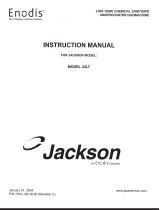
Design for the 30-75, 60-125
and 80-250 psi ranges
Design for the 0.5-3 ; 2-10 ; 6-20
and 15-40 psi ranges
Figure 1 — Spring-Diaphragm Actuators for 500, 500H and 500V Model Regulators
Design for the 150-750 psi range
8
7
5
1
4
2
13
16
6
15
11
28
14
10
23
22
3
27
Serial
Plate
Regulator
Plug
Stem
Plug Stem
Nuts
8
5
1
13
16
6
17
9
11
10
2
4
3
Serial
Plate
Regulator
Plug
Stem
Plug Stem
Nuts
PARTS REFERENCE
1 Yoke
2 Spring Adjuster
3 Bushing (Incl. Ref. 2)
4 Lower Spring Seat
5 Actuator Spring
6 Actuator Stem
7 Cap Screw (L. case to yoke)
8 Diaphragm Case (Lower)
9
(2)
Diaphragm Chamber
10 Diaphragm Plate
11 Diaphragm •
13 Diaphragm Case (Upper)
14
(1)
Diaphragm Washer
15 Cap Screw (Diaph.case)
16 Nut (Diaph.case)
17
(2)
Stud (Diaph. case)
18 Stop Cup
21
(4)
Reducing Ring
22
(5)
Stop Screw
23
(5)
Stop Spacer
27
(1)
Upper Spring Washer
28
(1)
Locknut (Actuator stem)
30 Spacer Ring (size 3.5 only)
• Recommended spare parts
(1)
Only on 0.5-3 ; 2-10 ; 6-20 and 15-40 psi ranges
(2)
Only on 150-750 psi range
(4)
Only on 60-125 and 80-250 psi ranges
(5)
Only on 0.5-3 ; 2-10 ; 6-20 and 15-40 psi ranges actuators mounted on types 526 and 536H
regulators
Ref. Part Name Ref. Part Name Ref. Part Name

6 | Baker Hughes Copyright 2020 Baker Hughes Company. All rights reserved.
8
5
1
6
2
4
3
16
7
17
9
10
11
13
16
25
24
26
27
Regulator
Plug
Stem
Serial
Plate
Plug Stem
Nuts
3
2
4
1
5
7
8
6
16
27
9
10
11
15
12
13 14 28
26
25
24
29
25
Regulator
Plug
Stem
Serial
Plate
Plug Stem
Nuts
Figure 2 — Differential Pressure Actuators for 500-50, 500H-50 and 500V-50 Models Regulators
PARTS REFERENCE
High Pressure Case Design
1 Yoke
2 Spring Adjuster
3 Bushing (Incl. Ref. 2)
4 Lower Spring Seat
5 Actuator Spring
6 Actuator Stem
7 Cap Screw (L. case to yoke)
8 Diaphragm Case (Lower)
9 Diaphragm Chamber
10 Diaphragm Plate (Incl. w. Ref. 24)
11 Diaphragm •
12
(1)
Upper Diaphragm Plate
13 Diaphragm Case (Upper)
14
(1)
Diaphragm Washer
15
(1)
Cap Screw (Diaph.case)
16 Nut (Diaph.case)
17
(2)
Stud (Diaph. case)
24 Plunger Sub-assembly
25
(3)
O-Ring •
26 O-Ring Retainer
27 Upper Spring Seat (Incl. w. Ref. 6)
28
(1)
Locknut
29
(1)
Connection Adapter
Ref. Part Name Ref. Part Name Ref. Part Name
• Recommended spare parts
(1)
Only on Low Pressure Case Design
(2)
Only on High Pressure Case Design
(3)
Qty: 2 on Low Pressure Case Design
Qty: 1 on High Pressure Case Design
3. Installation
On steam service, the regulator should be installed with the
actuator down so that the diaphragm will be protected by a
condensate barrier. If installed otherwise, an adequate
condensate barrier must be incorporated.
In the Spring Diaphragm Actuators, the 1/2” NPT pressure
connection is located on the upper diaphragm case (13).
In the Differential Pressure Actuators, the 1/2” NPT high
pressure connection is located on the upper diaphragm case
(13) and the 1/2” NPT low pressure connection is located on
the diaphragm chamber (9) or on the connection adapter (29).
Refer to Regulators Body S/A Instructions for installation
according to the regulator function.
Low Pressure Case Design

Masoneilan 10900 Series Actuator Instruction Manual | 7
Copyright 2020 Baker Hughes Company. All rights reserved.
4. Adjustment
When pressure setting has been specified in order, the regulator
is set accordingly at the factory for test. Then, the spring
compression is fully removed to avoid unnecessary stress
to parts (diaphragm, spring) during the stocking.
The regulator pressure range is engraved on the serial plate.
Proceed as follows :
• Open stop valve on the outlet side of the regulator and
partially open stop valve on the inlet side, allowing pressure
in the system to build up slowly.
• Open controlled pressure line valve(s) and check setting by
means of the gauge(s). Set by means of the spring adjuster
(2) of the actuator.
Note: To increase pressure setting (or pressure
differential), turn adjusting screw clockwise to compress
the spring. To decrease the setting, turn adjusting screw
counterclockwise to relieve spring compression.
• Fully open stop valve on the inlet side of the regulator.
5. Maintenance
Regulator must be isolated and pressure vented before
disassembly.
Replacing diaphragm
On Spring Diaphragm Actuators
(500 Series Regulators - Figure 1)
• Remove the controlled pressure line from the diaphragm case
(13) and relieve all spring compression by unscrewing spring
adjuster (2).
Remove upper diaphragm case (13), [nuts (16) and screws
(15)], [not screws (15) on 150-750 psi range].
a) On 0.5-3 / 2-10 / 6-20 / 15-40 / 30-75 / 60-125 and 80-250
psi ranges:
Remove locknut (28), diaphragm washer (14) and diaphragm (11).
b) On 150-750 psi range:
Remove diaphragm (11).
Note: By means of a wrench applied on the plug stem
nuts, hold the actuator stem during this operation.
• Install new diaphragm and reassemble by reversing of the
above description order.
• Readjust the spring compression (see above).
On Differential Actuators
(500-50 Series Regulators - Figure 2)
a. On low pressure case design:
• Remove the high and low pressure lines from the
diaphragm case (13) and the diaphragm chamber (9).
• Relieve all spring compression by unscrewing spring
adjuster (2).
• Remove nuts (16) and cap screws (15). Remove upper
diaphragm case (13).
• Remove locknut (28), upper diaphragm plate (12),
upper O-Ring (25), washer (14) and diaphragm (11).
• Install new diaphragm and reassemble by reversing of
the above description order. Replace upper O-Ring (25) if
necessary.
• Readjust the spring compression (see above).
b. On high pressure case design:
• Remove the high and low pressure lines from the
diaphragm case (13) and the diaphragm chamber (9).
• Relieve all spring compression by unscrewing spring
adjuster (2).
• Remove nuts (16), upper diaphragm case (13) and
diaphragm (11).
• Install new diaphragm and reassemble by reversing of the
above description order.
• Readjust the spring compression (see above).
Replacing O-ring(s) (25)
(low and high pressure case)
On differential actuators, (Figure 2)
• Disassemble the actuator head as described on the
paragraph : “Replacing diaphragm”.
• Remove diaphragm chamber (9) with plunger S/A (24).
• With a wrench applied over O-Ring retainer (26), unscrew
it out of diaphragm chamber (9).
• Remove O-Ring (25), being careful not to damage plunger.
Install new O-Ring, replace and tighten O-Ring retainer (26).
• Reassemble and readjust spring compression.
Uniformly tighten all diaphragm case nuts (16) when
reassembling.
It is necessary to proceed with adjustment before servicing.

Tech Field Support & Warranty:
Phone: +1-866-827-5378
valvesupport@bakerhughes.com
Copyright 2020 Baker Hughes Company. All rights reserved. Baker Hughes provides this information on an
“as is” basis for general information purposes. Baker Hughes does not make any representation as to the
accuracy or completeness of the information and makes no warranties of any kind, specic, implied or oral,
to the fullest extent permissible by law, including those of merchantability and tness for a particular purpose
or use. Baker Hughes hereby disclaims any and all liability for any direct, indirect, consequential or special
damages, claims for lost prots, or third party claims arising from the use of the information, whether a claim
is asserted in contract, tort, or otherwise. Baker Hughes reserves the right to make changes in specications
and features shown herein, or discontinue the product described at any time without notice or obligation.
Contact your Baker Hughes representative for the most current information. The Baker Hughes logo and
Masoneilan are trademarks of Baker Hughes Company. Other company names and product names used in
this document are the registered trademarks or trademarks of their respective owners.
BHMN-10900-IOM-31593D-0720 07/2020
Direct Sales Office Locations
Find the nearest local Channel Partner in your area:
valves.bakerhughes.com/contact-us
valves.bakerhughes.com
Australia
Brisbane
Phone: +61-7-3001-4319
Perth
Phone: +61-8-6595-7018
Melbourne
Phone: +61-3-8807-6002
Brazil
Phone: +55-19-2104-6900
China
Phone: +86-10-5738-8888
France
Courbevoie
Phone: +33-1-4904-9000
India
Mumbai
Phone: +91-22-8354790
New Delhi
Phone: +91-11-2-6164175
Italy
Phone: +39-081-7892-111
Japan
Tokyo
Phone: +81-03-6871-9008
Korea
Phone: +82-2-2274-0748
Malaysia
Phone: +60-3-2161-03228
Mexico
Phone: +52-55-3640-5060
Russia
Veliky Novgorod
Phone: +7-8162-55-7898
Moscow
Phone: +7-495-585-1276
Saudi Arabia
Phone: +966-3-341-0278
Singapore
Phone: +65-6861-6100
South Africa
Phone: +27-11-452-1550
South & Central
America and the Caribbean
Phone: +55-12-2134-1201
Spain
Phone: +34-935-877-605
United Arab Emirates
Phone: +971-4-8991-777
United Kingdom
Phone: +44-7919-382-156
United States
Houston, Texas
Phone: +1-713-966-3600
bakerhughes.com
/