Sony STR-DB830 User manual

Category
AV receivers
Type
User manual

This manual is also suitable for

STR-DB930
STR-DB830
GB
FR
NL
3-866-968-51(1)
FM Stereo
FM-AM Receiver
1999 by Sony Corporation
SE
Operating Instructions
Mode d’emploi
Gebruiksaanwijzing
Bruksanvisning
2
GB
WARNING
To prevent fire or shock
hazard, do not expose the
unit to rain or moisture.
To avoid electrical shock,
do not open the cabinet.
Refer servicing to qualified
personnel only.
Do not install the
appliance in a confined
space, such as a bookcase
or built-in cabinet.
Precautions
On safety
Should any solid object or liquid fall into
the cabinet, unplug the receiver and have it
checked by qualified personnel before
operating it any further.
On power sources
• Before operating the receiver, check that
the operating voltage is identical with
your local power supply. The operating
voltage is indicated on the nameplate at
the rear of the receiver.
• The unit is not disconnected from the AC
power source (mains) as long as it is
connected to the wall outlet, even if the
unit itself has been turned off.
• If you are not going to use the receiver
for a long time, be sure to disconnect the
receiver from the wall outlet. To
disconnect the AC power cord, grasp the
plug itself; never pull the cord.
• AC power cord must be changed only at
the qualified service shop.
On placement
• Place the receiver in a location with
adequate ventilation to prevent heat
buildup and prolong the life of the
receiver.
• Do not place the receiver near heat
sources, or in a place subject to direct
sunlight, excessive dust or mechanical
shock.
• Do not place anything on top of the
cabinet that might block the ventilation
holes and cause malfunctions.
On operation
Before connecting other components, be
sure to turn off and unplug the receiver.
On cleaning
Clean the cabinet, panel and controls with
a soft cloth slightly moistened with a mild
detergent solution. Do not use any type of
abrasive pad, scouring powder or solvent
such as alcohol or benzine.
If you have any question or problem
concerning your receiver, please
consult your nearest Sony dealer.
3
GB
About This Manual
The instructions in this manual are for models STR-DB930
and STR-DB830. Check your model number by looking at
the upper right corner of the front panel. In this manual,
the STR-DB930 is used for illustration purposes unless
stated otherwise. Any difference in operation is clearly
indicated in the text, for example, “STR-DB930 only.”
Type of differences
Model DB930 DB830
Feature
5 audio/5 video inputs r
4 audio/5 video inputs r
TABLE OF CONTENTS
Hooking Up the Components 4
Unpacking 4
Antenna Hookups 5
Audio Component Hookups 6
Video Component Hookups 8
Digital Component Hookups 9
5.1CH Input Hookups 11
Other Hookups 12
Hooking Up and Setting Up the
Speaker System 14
Speaker System Hookup 15
Performing Initial Setup Operations 17
Multi Channel Surround Setup 18
Before You Use Your Receiver 22
Location of Parts and Basic
Operations 24
Front Panel Parts Description 24
Enjoying Surround Sound 29
Selecting a Sound Field 30
Understanding the Multi-Channel Surround Displays 34
Customizing Sound Fields 36
Receiving Broadcasts 41
Storing FM Stations Automatically (AUTOBETICAL) 42
Direct Tuning 43
Automatic Tuning 43
Preset Tuning 44
Using the Radio Data System (RDS) 45
Other Operations 48
Naming Preset Stations and Program Sources 49
Recording 49
Adjustments Using the SET UP Button 50
Additional Information 52
Troubleshooting 52
Specifications 54
Glossary 56
Tables of Settings Using SUR, LEVEL, EQ, and SET
UP buttons 57
Index 59
Conventions
The instructions in this manual describe the controls on
the receiver. You can also use the controls on the
supplied remote if they have the same or similar names
as those on the receiver. For details on the use of your
remote, refer to the separate operating instructions
supplied with the remote.
The following icon is used in this manual:
z Indicates hints and tips for making the task easier.
This receiver incorporates Dolby
* Digital and Pro Logic
Surround and the DTS** Digital Surround System.
*
Manufactured under license from Dolby Laboratories.
“Dolby”, “AC-3”, “Pro Logic” and the double-D symbol a are
trademarks of Dolby Laboratories.
**
Manufactured under license from Digital Theater Systems, Inc. US
Pat. No. 5,451,942 and other worldwide patents issued and pending.
“DTS” and “DTS Digital Surround” are trademarks of Digital
Theater Systems, Inc. © 1996 Digital Theater Systems, Inc. All
rights reserved.
Demonstration Mode
The demonstration will activate the first time you turn on
the power. When the demonstration starts, the following
message appears in the display twice:
“Now Demonstration Mode!! If you finish
demonstration, please press POWER KEY while
this message appears in the display. Thank you!”
To cancel the demonstration
Press 1/u to turn the receiver off during the previous
message. The next time you turn the receiver on, the
demonstration will not appear.
To view the demonstration
Hold down SET UP and press 1/u to turn on the power.
Note
Running the demonstration will clear the receiver’s
memory. For details on what will be cleared, see “Clearing
the receiver's memory” on page 17.
GB
4
GB
Hooking Up
the
Components
This chapter describes how to connect
various audio and video components
to the receiver. Be sure to read the
sections for the components you have
before you actually connect them to
the receiver.
Unpacking
Check that you received the following items with the unit:
FM wire antenna (1)
AM loop antenna (1)
STR-DB930 only
Remote commander RM-LJ302 (remote) (1)
LR6 (size-AA) alkaline batteries (3)
STR-DB830 only
Remote commander RM-PP402 (remote) (1)
R6 (size-AA) batteries (2)
Inserting batteries into the remote
Insert the LR6 (STR-DB930) or R6 (STR-DB830) (size-AA)
batteries with the + and – properly oriented in the battery
compartment. When using the remote, point it at the
remote sensor g on the receiver.
For details, refer to the operating instructions supplied
with your remote.
z
When to replace batteries
Under normal conditions, the batteries should last for about 3
months (STR-DB930 only) or 6 months (STR-DB830 only). When
the remote no longer operates the receiver, replace all batteries
with new ones.
Notes
Do not leave the remote in an extremely hot or humid place.
Do not use a new battery with an old one.
Do not expose the remote sensor to direct sunlight or lighting
apparatuses. Doing so may cause a malfunction.
If you don’t use the remote for an extended period of time,
remove the batteries to avoid possible damage from battery
leakage and corrosion.
This remote is designed for use with alkaline batteries only. Do
not use a combination of different battery types (STR-DB930
only).
Before you get started
Turn off the power to all components before making
any connections.
Do not connect the AC power cords until all of the
connections are completed.
Be sure to make connections firmly to avoid hum and
noise.
When connecting an audio/video cord, be sure to
match the color-coded pins to the appropriate jacks on
the components: yellow (video) to yellow; white (left,
audio) to white; and red (right, audio) to red.
5
GB
Hooking Up the Components
SUB WOOFER
SUB
WOOFER
4 8
BA
R
L
R
L
R
LRL
+
SPEAKERS
IMPEDANCE USE 4-16
IN
L
R
L
R
REC OUT
SIGNAL
GND
AM
FM
75
COAXIAL
y
y
ANTENNA
TAPE
IMPEDANCE
SELECTOR
IN
PHONO
IN
CD
REARFRONT CENTER
REARFRONT
5.1CH INPUT
CENTER
DVD
COAXIAL
IN
DVD
OPTICAL
IN
TV/LD
OPTICAL
IN
MD/DAT
OPTICAL
IN
MD/DAT
OPTICAL
OUT
REARFRONT
PRE OUT
CENTER
DIGITAL
MONITOR
INREC OUT
MD/DAT
AUDIO
IN
IN
VIDEO
OUT
VIDEO
S-VIDEO
IN
VIDEO
S-VIDEO
IN
VIDEO
S-VIDEO
OUT
VIDEO
S-VIDEO
OUT
VIDEO
S-VIDEO
IN
VIDEO
AUDIO
OUT
VIDEO 1
2ND AUDIO OUT
AUDIO
IN
TV/LD
AUDIO
IN
DVD
AUDIO
IN
AUDIO
OUT
VIDEO 2
RL
AC OUTLET
CONTROL A1
FM wire antenna
(supplied)
AM loop antenna
(supplied)
Important
If you connect the receiver to an outdoor antenna, ground
it against lightning. To prevent a gas explosion, do not
connect the ground wire to a gas pipe.
Note
Do not use the y SIGNAL GND terminal for grounding the
receiver.
Terminals for connecting the antennas
Connect the To the
AM loop antenna AM terminals
FM wire antenna FM 75 COAXIAL terminal
Antenna Hookups
Notes on antenna hookups
To prevent noise pickup, keep the AM loop antenna
away from the receiver and other components.
Be sure to fully extend the FM wire antenna.
After connecting the FM wire antenna, keep it as
horizontal as possible.
Ground wire
(not supplied)
To ground
AM
FM
75
COAXIAL
y
ANTENNA
z
If you have poor FM reception
Use a 75-ohm coaxial cable (not supplied) to connect the receiver
to an outdoor FM antenna as shown below.
Outdoor FM antenna Receiver
6
GB
Hooking Up the Components
IN OUT
IN OUT
SUB
WOOFER
SUB WOOFER
4 8
BA
R
L
R
L
R
LRL
SPEAKERS
IMPEDANCE USE 4-16
IN
L
R
L
R
REC OUT
SIGNAL
GND
AM
FM
75
COAXIAL
y
y
ANTENNA
TAPE
IMPEDANCE
SELECTOR
IN
PHONO
IN
CD
REARFRONT CENTER
REARFRONT
5.1CH INPUT
CENTER
DVD
COAXIAL
IN
MD/DAT
OPTICAL
IN
MD/DAT
OPTICAL
OUT
REARFRONT
PRE OUT
CENTER
DIGITAL
MONITOR
INREC OUT
MD/DAT
AUDIO
IN
IN
VIDEO
OUT
VIDEO
S-VIDEO
IN
VIDEO
S-VIDEO
IN
VIDEO
S-VIDEO
OUT
VIDEO
S-VIDEO
OUT
VIDEO
S-VIDEO
IN
VIDEO
AUDIO
OUT
VIDEO 1
2ND AUDIO OUT
AUDIO
IN
AUDIO
IN
AUDIO
IN
AUDIO
OUT
VIDEO 2
RL
AC OUTLET
LINE
L
R
LINE
INPUT OUTPUT
LINE
L
R
LINE
INPUT OUTPUT
LINE
L
R
OUTPUT
ç
ç
ç
ç
+
DVD
OPTICAL
IN
TV/LD
OPTICAL
IN
TV/LD DVD
CONTROL A1
Jacks for connecting audio components
Connect a To the
Turntable PHONO jacks
CD player CD jacks
Tape deck TAPE jacks
MD deck or DAT deck MD/DAT jacks
Note on audio component hookups
If your turntable has a ground wire, connect it to the
y SIGNAL GND terminal on the receiver.
Required cords
Audio cords (not supplied)
When connecting a cord, be sure to match the color-coded pins to
the appropriate jacks on the components.
Audio Component Hookups
Turntable
Tape deck
MD/DAT deck
CD player
White (L) White (L)
Red (R) Red (R)
STR-DB930
7
GB
Hooking Up the Components
IN OUT
SUB
WOOFER
SUB WOOFER
4 8
BA
R
L
R
L
R
LRL
SPEAKERS
IMPEDANCE USE 4-16
L
R
L
R
SIGNAL
GND
AM
FM
75
COAXIAL
y
y
ANTENNA
IMPEDANCE
SELECTOR
IN
PHONO
IN
CD
REARFRONT CENTER
REARFRONT
5.1CH INPUT
CENTER
DVD
COAXIAL
IN
MD/TAPE
OPTICAL
IN
MD/TAPE
OPTICAL
OUT
REARFRONT
PRE OUT
CENTER
DIGITAL
MONITOR
INREC OUT
MD/TAPE
AUDIO
IN
IN
VIDEO
OUT
VIDEO
IN
VIDEO
S-VIDEO
IN
VIDEO
S-VIDEO
OUT
VIDEO
S-VIDEO
OUT
VIDEO
S-VIDEO
IN
VIDEO
AUDIO
OUT
VIDEO 1
AUDIO
IN
AUDIO
IN
AUDIO
IN
AUDIO
OUT
VIDEO 2
RL
AC OUTLET
LINE
L
R
LINE
INPUT OUTPUT
LINE
L
R
OUTPUT
ç
ç
+
DVD
OPTICAL
IN
TV/LD
OPTICAL
IN
TV/LD DVD
CONTROL A1
Jacks for connecting audio components
Connect a To the
Turntable PHONO jacks
CD player CD jacks
MD deck or Tape deck MD/TAPE jacks
Note on audio component hookups
If your turntable has a ground wire, connect it to the
y SIGNAL GND terminal on the receiver.
Required cords
Audio cords (not supplied)
When connecting a cord, be sure to match the color-coded pins to
the appropriate jacks on the components.
Turntable
MD/Tape deck
CD player
White (L) White (L)
Red (R) Red (R)
STR-DB830
8
GB
Hooking Up the Components
IN OUT IN OUT
SUB
WOOFER
SUB WOOFER
4 8
BA
R
L
R
L
R
LRL
SPEAKERS
IMPEDANCE USE 4-16
IN
L
R
L
R
REC OUT
SIGNAL
GND
AM
FM
75
COAXIAL
y
y
ANTENNA
TAPE
IMPEDANCE
SELECTOR
IN
PHONO
IN
CD
REARFRONT CENTER
REARFRONT
5.1CH INPUT
CENTER
DVD
COAXIAL
IN
MD/DAT
OPTICAL
IN
MD/DAT
OPTICAL
OUT
REARFRONT
PRE OUT
CENTER
DIGITAL
MONITOR
INREC OUT
MD/DAT
AUDIO
IN
IN
VIDEO
OUT
VIDEO
S-VIDEO
IN
VIDEO
S-VIDEO
IN
VIDEO
S-VIDEO
OUT
VIDEO
S-VIDEO
OUT
VIDEO
S-VIDEO
IN
VIDEO
AUDIO
OUT
VIDEO 1
2ND AUDIO OUT
AUDIO
IN
AUDIO
IN
AUDIO
IN
AUDIO
OUT
VIDEO 2
RL
AC OUTLET
ç
ç
VIDEO
OUT
R
VIDEO
IN
AUDIO
OUT
AUDIO
IN
INPUT OUTPUT
L
ç
ç
VIDEO
OUT
R
VIDEO
IN
AUDIO
OUT
AUDIO
IN
INPUT OUTPUT
L
VIDEO
IN
INPUT
RL
AUDIO OUT VIDEO
OUT
OUTPUT
RL
AUDIO OUT VIDEO
OUT
OUTPUT
+
DVD
OPTICAL
IN
TV/LD
OPTICAL
IN
TV/LD DVD
CONTROL A1
To the front panel
Note on video component hookups
You can connect your TV’s audio output jacks to the TV/
LD AUDIO IN jacks on the receiver and apply sound
effects to the audio from the TV. In this case, do not
connect the TV’s video output jack to the TV/LD VIDEO
IN jack on the receiver. If you are connecting a separate
TV tuner (or LD player), connect both the audio and video
output jacks to the receiver as shown above.
z
When using the S-video jacks instead of the video jacks
Your monitor must also be connected via an S-video jack. S-video
signals are on a separate bus from the video signals and will not
be output through the video jacks.
Jacks for connecting video components
Connect a To the
TV tuner or LD player TV/LD jacks
VCR VIDEO 1 jacks
Additional VCR VIDEO 2 jacks
DVD player DVD jacks
TV monitor MONITOR VIDEO OUT jack
Camcorder or video game VIDEO 3 INPUT jacks on the
front panel
Required cords
Audio/video cords (not supplied)
When connecting a cord, be sure to match the color-coded pins to
the appropriate jacks on the components.
Video cord for connecting a TV monitor (not supplied)
Video Component Hookups
Camcorder
or video
game
TV monitor
TV tuner or LD player
DVD player
Yellow Yellow
Yellow (video) Yellow (video)
White (L/audio) White (L/audio)
Red (R/audio) Red (R/audio)
VCR
VCR
9
GB
Hooking Up the Components
SUB WOOFER
SUB
WOOFER
4 8
BA
R
L
R
L
R
LRL
SPEAKERS
IMPEDANCE USE 4-16
IN
L
R
L
R
REC OUT
SIGNAL
GND
AM
FM
75
COAXIAL
y
y
ANTENNA
TAPE
IMPEDANCE
SELECTOR
IN
PHONO
IN
CD
REARFRONT CENTER
REARFRONT
5.1CH INPUT
CENTER
MD/DAT
OPTICAL
IN
MD/DAT
OPTICAL
OUT
REARFRONT
PRE OUT
CENTER
DIGITAL
MONITOR
INREC OUT
MD/DAT
AUDIO
IN
IN
VIDEO
OUT
VIDEO
S-VIDEO
IN
VIDEO
S-VIDEO
IN
VIDEO
S-VIDEO
OUT
VIDEO
S-VIDEO
OUT
VIDEO
S-VIDEO
IN
VIDEO
AUDIO
OUT
VIDEO 1
2ND AUDIO OUT
AUDIO
IN
AUDIO
IN
AUDIO
IN
AUDIO
OUT
VIDEO 2
RL
AC OUTLET
VIDEO
OUT
R
AUDIO
OUT
OUTPUT
L
DIGITAL
COAXIAL
OUTPUT
VIDEO
OUT
R
AUDIO
OUT
OUTPUT
L
DIGITAL
OPTICAL
OUTPUT
DIGITAL
OPTICAL
OUTPUT
+
DVD
COAXIAL
IN
DVD
OPTICAL
IN
TV/LD
OPTICAL
IN
TV/LD DVD
CONTROL A1
TV/LD
VIDEO IN
DIGITAL
DVD/LD IN
(COAXIAL)
(OPTICAL)
AC-3 RF
OUT
VIDEO OUT
5
0
1
3
9
7
46
2
8
10
PHONES
SPEAKERS
A
OFF
A
+B
B
MASTER VOLUME
SHIFT FM/AM
– +
DOOR OPEN
PRESET TUNING
VIDEO 3 INPUT
RLVIDEOS-VIDEO AUDIO
VIDEO 1
FM MODE PTY EON
BASS BOOST
5.1CH INPUT EQUALIZER
INPUT MODE
PTY SELECT +
TUNING/
SOUND FIELD
A.F.D. MODE
2CH
MODE 2CH
BASS BOOST
A.F.D.
MEMORY RDS
VIDEO 2 VIDEO 3 DVD TV/LD TAPE MD/DAT CD TUNER PHONO
MULTI CHANNEL DECODING
SUR
LEVEL
EQ
DIMMER DISPLAY
+
SET UP
NAME
ENTER
MODE FUNCTION MUTING
DVD player (etc.)*
Required cords
Optical digital cords (not supplied)
Coaxial digital cord (not supplied)
Audio/video cords (not supplied)
When connecting a cord, be sure to match the color-coded pins to
the appropriate jacks on the components.
Connect the digital output jacks of your DVD player and
TV tuner (etc.) to the receiver’s digital input jacks to bring
the multi channel surround sound of a movie theater into
your home. To enjoy full effect of multi channel surround
sound, five speakers (two front speakers, two rear
speakers, and a center speaker) and a sub woofer are
required. You can also connect an LD player with an RF
OUT jack via an RF demodulator, like the Sony MOD-RF1
(not supplied).
Digital Component Hookups
TV tuner or LD player
Please note that you cannot connect an LD player’s AC-3 RF OUT jack directly to this unit’s digital input jacks. You must
first convert the RF signal to either an optical or coaxial digital signal. Connect the LD player to the RF demodulator, then
connect the RF demodulator’s optical output to this unit’s OPTICAL TV/LD IN jack. Refer to the instruction manual
supplied with your RF Demodulator for details on AC-3 RF hookups.
Example of LD player connected via an RF demodulator
RF demodulatorLD player
Black Black
Yellow Yellow
Yellow (video) Yellow (video)
White (L/audio) White (L/audio)
Red (R/audio) Red (R/audio)
DIGITAL
TV/LD IN
(OPTICAL)
Note
When making connections as shown above, be sure to set INPUT MODE (3 on page 25) manually. This unit may not operate correctly if
INPUT MODE is set to “AUTO.”
*
Make either coaxial or optical connections. We recommended making coaxial connections instead of optical connections.
10
GB
Hooking Up the Components
IN OUT
ç
IN
ç
ç
OUT
ç
LINE
L
R
LINE
INPUT OUTPUT
DIGITAL
IN
OPTICAL
OUT
SUB
WOOFER
SUB WOOFER
4 8
BA
R
L
R
L
R
LRL
SPEAKERS
IMPEDANCE USE 4-16
IN
L
R
L
R
REC OUT
SIGNAL
GND
AM
FM
75
COAXIAL
y
y
ANTENNA
TAPE
IMPEDANCE
SELECTOR
IN
PHONO
IN
CD
REARFRONT CENTER
REARFRONT
5.1CH INPUT
CENTER
MD/DAT
OPTICAL
IN
MD/DAT
OPTICAL
OUT
REARFRONT
PRE OUT
CENTER
DIGITAL
MONITOR
INREC OUT
MD/DAT
AUDIO
IN
IN
VIDEO
OUT
VIDEO
S-VIDEO
IN
VIDEO
S-VIDEO
IN
VIDEO
S-VIDEO
OUT
VIDEO
S-VIDEO
OUT
VIDEO
S-VIDEO
IN
VIDEO
AUDIO
OUT
VIDEO 1
2ND AUDIO OUT
AUDIO
IN
AUDIO
IN
AUDIO
IN
AUDIO
OUT
VIDEO 2
RL
AC OUTLET
+
DVD
COAXIAL
IN
DVD
OPTICAL
IN
TV/LD
OPTICAL
IN
TV/LD DVD
CONTROL A1
Digital Component Hookups
Required cords
Optical digital cords (not supplied)
Audio cords (not supplied)
When connecting a cord, be sure to match the color-coded pins to
the appropriate jacks on the components.
Connect the digital output jacks of your MD or DAT deck
to the receiver’s digital input jack and connect the digital
input jacks of your MD or DAT deck to the receiver’s
digital output jack. These connections allow you to make
digital recordings of a CDs played back through your
DVD (or LD player) and TV broadcasts.
Black Black
Notes
• Please note that you cannot make a digital recording of a digital multi channel surround signal.
• To make a digital recording from your CD player, connect the CD player’s digital output directly to the digital input on your MD or DAT
deck. Refer to the instructions supplied with your CD player and MD or DAT deck for details.
• The DVD OPTICAL and COAXIAL jacks are compatible with 32 kHz, 44.1 kHz, 48 kHz and 96 kHz sampling frequencies.
• The TV/LD OPTICAL IN jack and MD/DAT OPTICAL IN and OUT jacks are compatible with 32 kHz, 44.1 kHz, and 48 kHz sampling
frequencies.
• It is not possible to record analog signals to TAPE and VIDEO with only digital connections. To record analog signals, make analog
connections. To record digital signals, make digital connections.
• Input signals with 96 kHz sampling frequencies to the DVD OPTICAL or COAXIAL jacks. Using other jacks may result in intermittent
sound.
MD or DAT deck
White (L) White (L)
Red (R) Red (R)
11
GB
Hooking Up the Components
REAR
CENTER
WOOFER
5.1 CH OUTPUT
FRONT
SUB WOOFER
SUB
WOOFER
4 8
BA
R
L
R
L
R
LRL
SPEAKERS
IMPEDANCE USE 4-16
IN
L
R
L
R
REC OUT
SIGNAL
GND
AM
FM
75
COAXIAL
y
y
ANTENNA
TAPE
IMPEDANCE
SELECTOR
IN
PHONO
IN
CD
REARFRONT CENTER
REARFRONT
5.1CH INPUT
CENTER
MD/DAT
OPTICAL
IN
MD/DAT
OPTICAL
OUT
REARFRONT
PRE OUT
CENTER
DIGITAL
MONITOR
INREC OUT
MD/DAT
AUDIO
IN
IN
VIDEO
OUT
VIDEO
S-VIDEO
IN
VIDEO
S-VIDEO
IN
VIDEO
S-VIDEO
OUT
VIDEO
S-VIDEO
OUT
VIDEO
S-VIDEO
IN
VIDEO
AUDIO
OUT
VIDEO 1
2ND AUDIO OUT
AUDIO
IN
AUDIO
IN
AUDIO
IN
AUDIO
OUT
VIDEO 2
RL
AC OUTLET
+
DVD
COAXIAL
IN
DVD
OPTICAL
IN
TV/LD
OPTICAL
IN
TV/LD DVD
CONTROL A1
5.1CH INPUT
VIDEO OUT
SUB WOOFER
SPEAKERS
REAR/CENTER
SPEAKERS
FRONT
5
0
1
3
9
7
46
2
8
10
PHONES
SPEAKERS
A
OFF
A
+B
B
MASTER VOLUME
SHIFT FM/AM
– +
DOOR OPEN
PRESET TUNING
VIDEO 3 INPUT
RLVIDEOS-VIDEO AUDIO
VIDEO 1
FM MODE
BASS BOOST
5.1CH INPUT EQUALIZER
INPUT MODE
SOUND FIELD
A.F.D. MODE
2CH
MODE 2CH
BASS BOOST
A.F.D.
MEMORY
VIDEO 2 VIDEO 3 TAPE MD/DAT CD TUNER PHONO
MULTI CHANNEL DECODING
SUR
LEVEL
EQ
DIMMER DISPLAY
+
SET UP
NAME
ENTER
MODE FUNCTION MUTING
PTY EONPTY SELECT +
TUNING/
RDS
DVD TV/LD
5.1CH Input Hookups
Required cords
Audio cords (not supplied)
Two for the 5.1CH INPUT FRONT and REAR jacks
White (L) White (L)
Red (R) Red (R)
Monaural audio cords (not supplied)
Two for the 5.1CH INPUT CENTER and SUB WOOFER jacks
Black Black
Video cord (not supplied)
One for the DVD VIDEO IN jacks (etc.)
Yellow Yellow
Note
When using the connections described below, adjust the level of
your surround speakers and subwoofer from the DVD player or
multichannel decoder.
Although this receiver incorporates a multi channel
decoder, it is also equipped with 5.1CH INPUT jacks.
These connections allow you to enjoy multichannel
software encoded in formats other than Dolby Digital
(AC-3) and DTS. If your DVD player is equipped with
5.1CH OUTPUT jacks, you can connect them directly to
this unit to enjoy the sound of the DVD player’s multi
channel decoder. Alternatively, the 5.1CH INPUT jacks
can be used to connect an external multi channel decoder.
To fully enjoy multi channel surround sound, you will
need five speakers (two front speakers, two rear speakers,
and a center speaker) and a subwoofer. Refer to the
instruction manual supplied with your DVD player, multi
channel decoder, etc., for details on the 5.1 channel input
hookups.
Example of a DVD player hookup using the 5.1CH INPUT jacks
Note
See page 15 for details on speaker system hookup.
DVD player
Front Speaker (L)
Front Speaker (R)
Rear Speaker (L)
Rear Speaker (R)
Center Speaker
Active Woofer
DVD player,
Multichannel decoder, etc.
DVD
IN VIDEO etc.
12
GB
Hooking Up the Components
AC OUTLET
*
CONTROL A1
b
SUB
WOOFER
SUB WOOFER
4 8
BA
R
L
R
L
R
LRL
SPEAKERS
IMPEDANCE USE 4-16
IN
L
R
L
R
REC OUT
SIGNAL
GND
AM
FM
75
COAXIAL
y
y
ANTENNA
TAPE
IMPEDANCE
SELECTOR
IN
PHONO
IN
CD
REARFRONT CENTER
REARFRONT
5.1CH INPUT
CENTER
MD/DAT
OPTICAL
IN
MD/DAT
OPTICAL
OUT
REARFRONT
PRE OUT
CENTER
DIGITAL
MONITOR
INREC OUT
MD/DAT
AUDIO
IN
IN
VIDEO
OUT
VIDEO
S-VIDEO
IN
VIDEO
S-VIDEO
IN
VIDEO
S-VIDEO
OUT
VIDEO
S-VIDEO
OUT
VIDEO
S-VIDEO
IN
VIDEO
AUDIO
OUT
VIDEO 1
2ND AUDIO OUT
AUDIO
IN
AUDIO
IN
AUDIO
IN
AUDIO
OUT
VIDEO 2
RL
AC OUTLET
+
DVD
COAXIAL
IN
DVD
OPTICAL
IN
TV/LD
OPTICAL
IN
TV/LD DVD
CONTROL A1
AC power cord
Required cords
Audio cords (not supplied)
When connecting a cord, be sure to match the color-coded pins to the
appropriate jacks on the components.
CONTROL A1 connecting cord (not supplied)
Black Black
*
The configuration, shape, and number of AC outlets on the rear panel varies according to the model and country to which the receiver is shipped.
To a wall outlet
Other Hookups
White (L) White (L)
Red (R) Red (R)
You can use the 2ND AUDIO OUT jacks to output the audio signal of the selected component to a stereo amplifier located
in another room. Use MODE and FUNCTION (2 on page 24 and 25) to turn the sub room output on or off.
Example of a sub room hookup using the 2ND AUDIO OUT jacks (STR-DB930 only)
Speaker (L)
Speaker (R)
Main room
Stereo amplifier
Sub room
2ND AUDIO OUT
(STR-DB930 only)
2ND
AUDIO
OUT
AUDIO
IN
SPEAKERS
R
L
5
0
1
3
9
7
46
2
8
10
PHONES
SPEAKERS
A
OFF
A
+
B
B
MASTER VOLUME
SHIFT FM/AM
– +
DOOR OPEN
PRESET TUNING
VIDEO 3 INPUT
RLVIDEOS-VIDEO AUDIO
VIDEO 1
FM MODE
BASS BOOST
5.1CH INPUT EQUALIZER
INPUT MODE
SOUND FIELD
A.F.D. MODE
2CH
MODE 2CH
BASS BOOST
A.F.D.
MEMORY
VIDEO 2 VIDEO 3 TAPE MD/DAT CD TUNER PHONO
MULTI CHANNEL DECODING
SUR
LEVEL
EQ
DIMMER DISPLAY
+
SET UP
NAME
ENTER
MODE FUNCTION MUTING
PTY EON
PTY SELECT
+
TUNING/
RDS
DVD TV/LD
Note
This function is not available when 5.1CH INPUT is selected.
13
GB
Hooking Up the Components
CONTROL A1 hookup
If you have a CONTROL A1 compatible Sony
CD player, tape deck, or MD deck
Use a CONTROL A1 cord (not supplied) to connect the
CONTROL A1
jack on the CD player, tape deck, or
MD deck to the CONTROL A1
jack on the receiver.
Refer to the separate manual “CONTROL-A1
Control
System” and the operating instructions supplied with
your CD player, tape deck, or MD deck for details.
Note
If you make CONTROL A1 connections from the receiver to
an MD deck that is also connected to a computer, do not
operate the receiver while using the “Sony MD Editor”
software. This may cause a malfunction.
If you have a Sony CD changer with a
COMMAND MODE selector
If your CD changer’s COMMAND MODE selector can
be set to CD 1, CD 2, or CD 3, be sure to set the
command mode to “CD 1” and connect the changer to
the CD jacks on the receiver.
If, however, you have a Sony CD changer with VIDEO
OUT jacks, set the command mode to “CD 2” and
connect the changer to the VIDEO 2 jacks on the
receiver.
Connecting the AC power cord
Before connecting the AC power cord of this receiver to a
wall outlet:
Connect the speaker system to the receiver (see page
15).
Turn the MASTER VOLUME control to the leftmost
position (0).
Connect the AC power cord(s) of your audio/video
components to a wall outlet.
If you connect other audio/video components to the AC
OUTLET on the receiver, the receiver will supply power
to the connected component, allowing you to turn the
whole system on or off when you turn the receiver on/off.
Caution
Make sure that the total power consumption of the component
connected to the receiver’s AC OUTLET does not exceed the
wattage stated on the rear panel. Do not connect high-wattage
electrical home appliances such as electric irons, fans, or TVs to
this outlet.
Note
If the AC power cord is disconnected for about two weeks, the
receiver’s entire memory will be cleaned and the demonstration
will start.
14
GB
Hooking Up
and Setting Up
the Speaker
System
This chapter describes how to hook
up your speaker system to the
receiver, how to position each speaker,
and how to set up your speakers to
enjoy multi channel surround sound.
Brief descriptions of buttons and control
used to set up the speaker system
SET UP button: Press to enter the setup mode when
specifying speaker types and distances.
Cursor buttons ( / ): Use to select parameters after
pressing the SET UP button.
Jog dial: Use to adjust the setting of each parameter.
Cursor buttons
Jog dial
5
0
1
3
9
7
46
2
8
10
PHONES
SPEAKERS
A
OFF
A
+
B
B
MASTER VOLUME
SHIFT FM/AM
– +
DOOR OPEN
PRESET TUNING
VIDEO 3 INPUT
RLVIDEOS-VIDEO AUDIO
VIDEO 1
FM MODE
BASS BOOST
5.1CH INPUT EQUALIZER
INPUT MODE
SOUND FIELD
A.F.D. MODE
2CH
MODE 2CH
BASS BOOST
A.F.D.
MEMORY
VIDEO 2 VIDEO 3 TAPE MD/DAT CD TUNER PHONO
MULTI CHANNEL DECODING
SUR
LEVEL
EQ
DIMMER DISPLAY
+
SET UP
NAME
ENTER
MODE FUNCTION MUTING
PTY EON
PTY SELECT
+
TUNING/
RDS
DVD TV/LD
SET UP
15
GB
Hooking Up and Setting Up the Speaker System
IMPEDANCE
SELECTOR
FRONT
SPEAKERS B
SUB WOOFER
SUB
WOOFER
4 8
BA
R
L
R
L
R
LRL
SPEAKERS
IMPEDANCE USE 4-16
IN
L
R
L
R
REC OUT
SIGNAL
GND
AM
FM
75
COAXIAL
y
y
ANTENNA
TAPE
IMPEDANCE
SELECTOR
IN
PHONO
IN
CD
REARFRONT CENTER
REARFRONT
5.1CH INPUT
CENTER
MD/DAT
OPTICAL
IN
MD/DAT
OPTICAL
OUT
REARFRONT
PRE OUT
CENTER
DIGITAL
MONITOR
INREC OUT
MD/DAT
AUDIO
IN
IN
VIDEO
OUT
VIDEO
S-VIDEO
IN
VIDEO
S-VIDEO
IN
VIDEO
S-VIDEO
OUT
VIDEO
S-VIDEO
OUT
VIDEO
S-VIDEO
IN
VIDEO
AUDIO
OUT
VIDEO 1
2ND AUDIO OUT
AUDIO
IN
AUDIO
IN
AUDIO
IN
AUDIO
OUT
VIDEO 2
RL
AC OUTLET
}
]
}
]
}
]
}
]
}
]
INPUT
AUDIO
IN
+
DVD
COAXIAL
IN
DVD
OPTICAL
IN
TV/LD
OPTICAL
IN
TV/LD DVD
CONTROL A1
Front speaker (R) Front speaker (L)
Center speaker
Active sub wooferRear speaker (R) Rear speaker (L)
z
To connect certain speakers to another amplifier
Use the PRE OUT jacks. The same signal is output from both the
SPEAKERS jacks and the PRE OUT jacks. For example, if you
want to connect just the front speakers to another amplifier,
connect that amplifier to the PRE OUT FRONT L and R jacks.
Notes on speaker system hookup
Twist the stripped ends of the speaker cords about 10
mm. Be sure to match the speaker cord to the
appropriate terminal on the components: + to + and –
to –. If the cords are reversed, the sound will be
distorted and will lack bass.
If you use front speakers with low maximum input
rating, adjust the volume carefully to avoid excessive
output on the speakers.
* See “Speaker impedance” on the next page.
** You can connect an active sub woofer to either of the two jacks. The
remaining jack can be used to connect a second active sub woofer.
Terminals for connecting the speakers
Connect the To the
Front speakers (8 or 4* ohm) SPEAKERS FRONT A terminals
Additional pair of front
speakers (8 or 4* ohm)
SPEAKERS FRONT B terminals
Rear speakers (8 or 4* ohm) SPEAKERS REAR terminals
Center speaker (8 or 4* ohm) SPEAKERS CENTER terminals
Active sub woofer PRE OUT SUB WOOFER jack**
Required cords
Speaker cords (not supplied)
One for each front, rear, and center speaker
(+) (+)
(–) (–)
Monaural audio cord (not supplied)
One for an active woofer
Black Black
Speaker System Hookup
16
GB
Hooking Up and Setting Up the Speaker System
Speaker impedance
To enjoy multi channel surround, connect front, center,
and rear speakers with a nominal impedance of 8 ohms or
higher, and set the speaker IMPEDANCE SELECTOR to
“8.” Check the instruction manual supplied with your
speakers if you’re not sure of their impedance. (This
information is usually printed on a label on the back of
the speaker.)
You may connect a pair of speakers with a nominal
impedance between 4 and 8 ohms to the SPEAKERS
terminals, if you set the IMPEDANCE SELECTOR to
“4Ω.
Note
Be sure to connect front speakers with a nominal impedance of 8
ohms or higher and set the IMPEDANCE SELECTOR to “4” if
you want to select both sets (A+B) of front speakers (see page 26).
Speaker System Hookup
To avoid short-circuiting the speakers
Short-circuiting of the speakers may damage the receiver.
To prevent this, make sure to take the following
precautions when connecting the speakers.
Make sure the stripped ends of each speaker cord
does not touch another speaker terminal or the
stripped end of another speaker cord.
Examples of poor conditions of the speaker cord
Stripped speaker cord is touching another speaker terminal.
Stripped cords are touching each other due to excessive
removal of insulation.
After connecting all the components, speakers,
and AC power cord, output a test tone to check
that all the speakers are connected correctly. For
details on outputting a test tone, see page 21.
If no sound is heard from a speaker while outputting a
test tone or a test tone is output from a speaker other than
the one whose name is currently displayed on the
receiver, the speaker may be short-circuited. If this
happens, check the speaker connection again.
17
GB
Hooking Up and Setting Up the Speaker System
Performing Initial Setup Operations
Once you have hooked up the speakers and turned on the
power, clear the receiver’s memory. Then specify the
speaker parameters (size, position, etc.) and perform any
other initial setup operations necessary for your system.
Before turning on the receiver
Make sure that you have:
Turned MASTER VOLUME to the leftmost position (0).
Selected the appropriate front speakers (see “7
SPEAKERS selector” on page 26).
Clearing the receiver’s memory
Before using your receiver for the first time, or when you
want to clear the receiver’s memory, do the following.
This procedure is not necessary if the demonstration
activates when you turn the power on.
1 Turn off the receiver.
2 Hold down 1/u for 5 seconds.
The currently selected function, then the
demonstration message appears in the display. All of
the following items are reset or cleared:
All preset stations are reset or cleared.
All sound field parameters are reset to their factory
settings.
All index names (of preset stations and program
sources) are cleared.
All adjustments made with the SET UP button are
reset to their factory settings.
The sound field memorized for each program source
and preset stations are cleared.
Performing initial setup operations
Before using your receiver for the first time, use the SET
UP button to adjust the setup parameters so that they
correspond to your system. You can adjust the following
items. For details on how to make adjustments, see the
page in parenthesis.
Speaker size and placement (pages 18~21).
Speaker distance (page 21).
Whether other components will turn on/off
automatically via the CONTROL A1
control system
(page 50).
STR-DB930 only: 2 way remote control system
operation (page 51).
5
0
1
3
9
7
46
2
8
10
PHONES
SPEAKERS
A
OFF
A
+
B
B
MASTER VOLUME
SHIFT FM/AM
– +
DOOR OPEN
PRESET TUNING
VIDEO 3 INPUT
RLVIDEOS-VIDEO AUDIO
VIDEO 1
FM MODE
BASS BOOST
5.1CH INPUT EQUALIZER
INPUT MODE
SOUND FIELD
A.F.D. MODE
2CH
MODE 2CH
BASS BOOST
A.F.D.
MEMORY
VIDEO 2 VIDEO 3 TAPE MD/DAT CD TUNER PHONO
MULTI CHANNEL DECODING
SUR
LEVEL
EQ
DIMMER DISPLAY
+
SET UP
NAME
ENTER
MODE FUNCTION MUTING
PTY EON
PTY SELECT
+
TUNING/
RDS
DVD TV/LD
1/u
18
GB
Hooking Up and Setting Up the Speaker System
Multi Channel Surround Setup
Specifying the speaker parameters
1 Press 1/u to turn on the receiver.
2 Press SET UP.
3 Press the cursor buttons ( or ) to select the
parameter you want to adjust.
4 Turn the jog dial to select setting you desire. The
setting is entered automatically.
5 Repeat steps 3 and 4 until you have set all of the
parameters that follow.
p Front speaker size (FRONT)
Initial setting : LARGE
If you connect large speakers that will effectively
reproduce bass frequencies, select “LARGE”. Normally,
select “LARGE”.
If the sound is distorted, or you feel a lack of surround
effects when using multi channel surround sound,
select “SMALL” to activate the bass redirection circuitry
and output the front channel bass frequencies from the
sub woofer.
When the front speaker is set to “SMALL”, the center
and rear speakers are also automatically set to
“SMALL” (unless previously set to “NO”).
For the best possible surround sound all speakers should
be the same distance from the listening position (A).
(However, this unit lets you to place the center speaker up
to 1.5 meters (5 feet) closer (B) and the rear speakers up
to 4.5 meters (15 feet) closer (C) to the listening position.
The front speakers can be placed from 1.0 to 12.0 meters (3
to 40 feet) from the listening position (A).)
You can place the rear speakers either behind you or to
the side, depending on the shape of your room (etc.).
Note
Do not place the center speaker farther away from the listening
position than the front speakers.
45°
90°
20°
A A
B
CC
45°
90°
20°
A A
B
CC
When placing rear speakers to your side
When placing rear speakers behind you
19
GB
Hooking Up and Setting Up the Speaker System
60°
90°
20°
A
B
30°
B
C C
A
z
About speaker sizes (LARGE and SMALL)
Internally, the LARGE and SMALL settings for each speaker
determine whether or not the internal sound processor will cut
the bass signal from that channel. When the bass is cut from a
channel the bass redirection circuitry sends the corresponding
bass frequencies to the sub woofer or other “LARGE” speaker.
However, since bass sounds have a certain amount of
directionality it best not to cut them, if possible. Therefore, even
when using small speakers, you can set them to “LARGE” if you
want to output the bass frequencies from that speaker. On the
other hand, if you are using a large speaker, but prefer not to
have bass frequencies output from that speaker, set it to
“SMALL”.
If the overall sound level is lower than you prefer set all speakers
to “LARGE”. If there is not enough bass you can use the
equalizer to boost the bass levels. To adjust the equalizer, see
page 38.
p Rear speaker position (REAR PL.)*
Initial setting : BEHIND
This parameter lets you specify the location of your rear
speakers for proper implementation of the Digital Cinema
Sound surround modes in the “VIRTUAL” sound fields.
Refer to the illustration below.
Select “SIDE” if the location of your rear speakers
corresponds to section A.
Select “MIDDLE” if the location of your rear speakers
corresponds to section B.
Select “BEHIND” if the location of your rear speakers
corresponds to section C.
This setting only effects the surround modes in the
“VIRTUAL” sound fields.
p Center speaker size (CENTER)
Initial setting : LARGE
If you a connect large speaker that will effectively
reproduce bass frequencies, select “LARGE”. Normally,
select “LARGE”. However, if the front speakers are set
to “SMALL”, you cannot set the center speaker to
“LARGE”.
If the sound is distorted, or you feel a lack of surround
effects when using multi channel surround sound,
select “SMALL” to activate the bass redirection circuitry
and output the center channel bass frequencies from the
front speakers (if set to “LARGE”) or sub woofer. *
1
If you do not connect the center speaker, select “NO”.
The sound of the center channel will be output from the
front speakers.*
2
p Rear speaker size (REAR)
Initial setting : LARGE
If you connect large speakers that will effectively
reproduce bass frequencies, select “LARGE”. Normally,
select “LARGE”. However, if the front speakers are set
to “SMALL”, you cannot set the rear speakers to
“LARGE”.
If the sound is distorted, or you feel a lack of surround
effects when using multi channel surround sound,
select “SMALL” to activate the bass redirection circuitry
and output the rear channel bass frequencies from the
sub woofer or other “LARGE” speakers.
If you do not connect rear speakers, select “NO”.*
3
z
*1~*3 correspond to the following Dolby Pro Logic modes
*
1
NORMAL
*
2
PHANTOM
*
3
3 STEREO
20
GB
Hooking Up and Setting Up the Speaker System
Multi Channel Surround Setup
p Sub woofer selection (SUB WOOFER)
Initial setting : YES
If you connect a sub woofer, select “YES”.
If you do not connect a sub woofer, select “NO”. This
activates the bass redirection circuitry and outputs the
LFE signals from other speakers.
In order to take full advantage of the Dolby Digital
(AC-3) bass redirection circuitry, we recommend that
you set your sub woofer’s cut off frequency as high as
possible.
p Front speaker distance (FRONT)
Initial setting : 5.0 meter
Set the distance from your listening position to the front
(left or right) speaker (A on page 18).
Front speaker distance can be set in 0.1 meter (1 foot)
steps from 1.0 to 12.0 meters (3 to 40 feet).
If both speakers are not placed an equal distance from
your listening position, set the distance to the closest
speaker.
p Center speaker distance (CENTER)
Initial setting : 5.0 meter
Set the distance from your listening position to the center
speaker.
Center speaker distance can be set in 0.1 meter (1 foot)
steps from a distance equal to the front speaker distance
(A on page 18) to a distance 1.5 meters (5 feet) closer to
your listening position (B on page 18).
Do not place the center speaker farther away from your
listening position than the front speakers.
p Rear speaker distance (REAR)
Initial setting : 3.5 meter
Set the distance from your listening position to the rear
(left or right) speaker.
Rear speaker distance can be set in 0.1 meter (1 foot)
steps from a distance equal to the front speaker distance
(A on page 18) to a distance 4.5 meters (15 feet) closer
to your listening position (C on page 18).
Do not place the rear speakers farther away from your
listening position than the front speakers.
If both speakers are not placed an equal distance from
your listening position, set the distance to the closest
speaker.
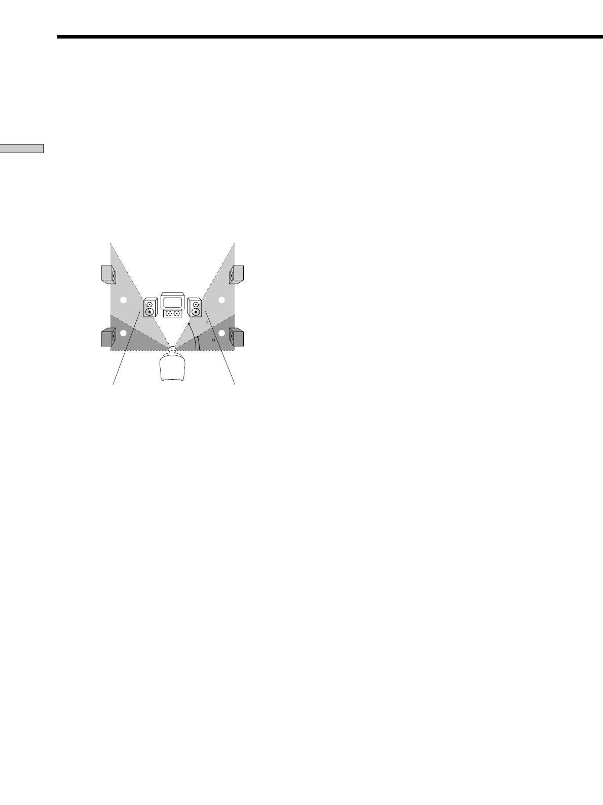
p Rear speaker height (REAR HGT.)*
Initial setting : LOW
This parameter lets you specify the height of your rear
speakers for proper implementation of the Digital Cinema
Sound surround modes in the “VIRTUAL” sound fields.
Refer to the illustration below.
Select “LOW” if the location of your rear speakers
corresponds to section A.
Select “HIGH” if the location of your rear speakers
corresponds to section B.
This setting only effects the surround modes in the
“VIRTUAL” sound fields.
* These parameters are not available when “Rear speaker
size (REAR)“ is set to “NO”.
z
About the rear speaker position (SIDE, MIDDLE, and BEHIND)
This setting is designed specifically for implementation of the
Digital Cinema Sound modes in the “VIRTUAL” sound fields.
With the Digital Cinema Sound modes, speaker position is not as
critical as other modes. All of the modes in the “VIRTUAL”
sound fields were designed under the premise that the rear
speaker would be located behind the listening position, but
presentation remains fairly consistent even with the rear speakers
positioned at a rather wide angle. However, if the speakers are
pointing toward the listener from the immediate left and right of
the listening position, the “VIRTUAL” sound fields will not be
effective unless the rear speaker position parameter is set to
“SIDE”.
Nevertheless, each listening environment has many variables,
like wall reflections, and you may obtain better results using
“BEHIND” or “MIDDLE” if your speakers are located high above
the listening position, even if they are to the immediate left and
right.
Therefore, although it may result in a setting contrary to the
“Rear speaker position” explanation, we recommend that you
playback multi channel surround encoded software and listen to
the effect each setting has on your listening environment. Choose
the setting that provides a good sense of spaciousness and that
best succeeds in forming a cohesive space between the surround
sound from the rear speakers and the sound of the front speakers.
If you are not sure which sounds best, select “BEHIND” and then
use the speaker distance parameter and speaker level
adjustments to obtain proper balance.
60
30
A
B
A
B
  • Page 1 1
  • Page 2 2
  • Page 3 3
  • Page 4 4
  • Page 5 5
  • Page 6 6
  • Page 7 7
  • Page 8 8
  • Page 9 9
  • Page 10 10
  • Page 11 11
  • Page 12 12
  • Page 13 13
  • Page 14 14
  • Page 15 15
  • Page 16 16
  • Page 17 17
  • Page 18 18
  • Page 19 19
  • Page 20 20
  • Page 21 21
  • Page 22 22
  • Page 23 23
  • Page 24 24
  • Page 25 25
  • Page 26 26
  • Page 27 27
  • Page 28 28
  • Page 29 29
  • Page 30 30
  • Page 31 31
  • Page 32 32
  • Page 33 33
  • Page 34 34
  • Page 35 35
  • Page 36 36
  • Page 37 37
  • Page 38 38
  • Page 39 39
  • Page 40 40
  • Page 41 41
  • Page 42 42
  • Page 43 43
  • Page 44 44
  • Page 45 45
  • Page 46 46
  • Page 47 47
  • Page 48 48
  • Page 49 49
  • Page 50 50
  • Page 51 51
  • Page 52 52
  • Page 53 53
  • Page 54 54
  • Page 55 55
  • Page 56 56
  • Page 57 57
  • Page 58 58
  • Page 59 59
  • Page 60 60
  • Page 61 61
  • Page 62 62
  • Page 63 63
  • Page 64 64
  • Page 65 65
  • Page 66 66
  • Page 67 67
  • Page 68 68
  • Page 69 69
  • Page 70 70
  • Page 71 71
  • Page 72 72
  • Page 73 73
  • Page 74 74
  • Page 75 75
  • Page 76 76
  • Page 77 77
  • Page 78 78
  • Page 79 79
  • Page 80 80
  • Page 81 81
  • Page 82 82
  • Page 83 83
  • Page 84 84
  • Page 85 85
  • Page 86 86
  • Page 87 87
  • Page 88 88
  • Page 89 89
  • Page 90 90
  • Page 91 91
  • Page 92 92
  • Page 93 93
  • Page 94 94
  • Page 95 95
  • Page 96 96
  • Page 97 97
  • Page 98 98
  • Page 99 99
  • Page 100 100
  • Page 101 101
  • Page 102 102
  • Page 103 103
  • Page 104 104
  • Page 105 105
  • Page 106 106
  • Page 107 107
  • Page 108 108
  • Page 109 109
  • Page 110 110
  • Page 111 111
  • Page 112 112
  • Page 113 113
  • Page 114 114
  • Page 115 115
  • Page 116 116
  • Page 117 117
  • Page 118 118
  • Page 119 119
  • Page 120 120
  • Page 121 121
  • Page 122 122
  • Page 123 123
  • Page 124 124
  • Page 125 125
  • Page 126 126
  • Page 127 127
  • Page 128 128
  • Page 129 129
  • Page 130 130
  • Page 131 131
  • Page 132 132
  • Page 133 133
  • Page 134 134
  • Page 135 135
  • Page 136 136
  • Page 137 137
  • Page 138 138
  • Page 139 139
  • Page 140 140
  • Page 141 141
  • Page 142 142
  • Page 143 143
  • Page 144 144
  • Page 145 145
  • Page 146 146
  • Page 147 147
  • Page 148 148
  • Page 149 149
  • Page 150 150
  • Page 151 151
  • Page 152 152
  • Page 153 153
  • Page 154 154
  • Page 155 155
  • Page 156 156
  • Page 157 157
  • Page 158 158
  • Page 159 159
  • Page 160 160
  • Page 161 161
  • Page 162 162
  • Page 163 163
  • Page 164 164
  • Page 165 165
  • Page 166 166
  • Page 167 167
  • Page 168 168
  • Page 169 169
  • Page 170 170
  • Page 171 171
  • Page 172 172
  • Page 173 173
  • Page 174 174
  • Page 175 175
  • Page 176 176
  • Page 177 177
  • Page 178 178
  • Page 179 179
  • Page 180 180
  • Page 181 181
  • Page 182 182
  • Page 183 183
  • Page 184 184
  • Page 185 185
  • Page 186 186
  • Page 187 187
  • Page 188 188
  • Page 189 189
  • Page 190 190
  • Page 191 191
  • Page 192 192
  • Page 193 193
  • Page 194 194
  • Page 195 195
  • Page 196 196
  • Page 197 197
  • Page 198 198
  • Page 199 199
  • Page 200 200
  • Page 201 201
  • Page 202 202
  • Page 203 203
  • Page 204 204
  • Page 205 205
  • Page 206 206
  • Page 207 207
  • Page 208 208
  • Page 209 209
  • Page 210 210
  • Page 211 211
  • Page 212 212
  • Page 213 213
  • Page 214 214
  • Page 215 215
  • Page 216 216
  • Page 217 217
  • Page 218 218
  • Page 219 219
  • Page 220 220
  • Page 221 221
  • Page 222 222
  • Page 223 223
  • Page 224 224
  • Page 225 225
  • Page 226 226
  • Page 227 227
  • Page 228 228
  • Page 229 229
  • Page 230 230
  • Page 231 231
  • Page 232 232
  • Page 233 233
  • Page 234 234
  • Page 235 235
  • Page 236 236

Sony STR-DB830 User manual

Category
AV receivers
Type
User manual
This manual is also suitable for

Ask a question and I''ll find the answer in the document

Finding information in a document is now easier with AI