Shure UA874 User manual

Category
Television antennas
Type
User manual
©2013 Shure Incorporated
27B16709 (Rev. 2)
Printed in U.S.A.
UA874
Active Directional Antenna
Antenne directionnelle active
Aktive Richtantenne
Antena direccional activa
Antenna direttiva attiva
Actieve richtantenne
Активная направленная антенна
Antena Direcional Ativa
Antena Terarah Aktif
ブ指向性
액티브 지향성 안테나
有源指向性天线
有源指向性天線
3
Active Directional Antenna
General Description
The Shure UA874 uses a log periodic dipole array to offer enhanced re-
ception when directed toward the desired coverage area. An integrated
amplifier and four gain settings compensate for varying degrees of coaxial
cable signal loss. The UA874 can be mounted on a microphone stand,
suspended from the ceiling, or mounted to a wall using the integrated
swivel adapter bracket.
Features
Low-noise signal amplifier compensates for insertion loss in coaxial
cable
Compatible with Shure wireless receivers and antenna distribution
systems that provide 10–15 V DC bias
Integrated threaded adapter mounts easily to microphone stands
Four-position gain selector switch
Shure quality, ruggedness, and reliability
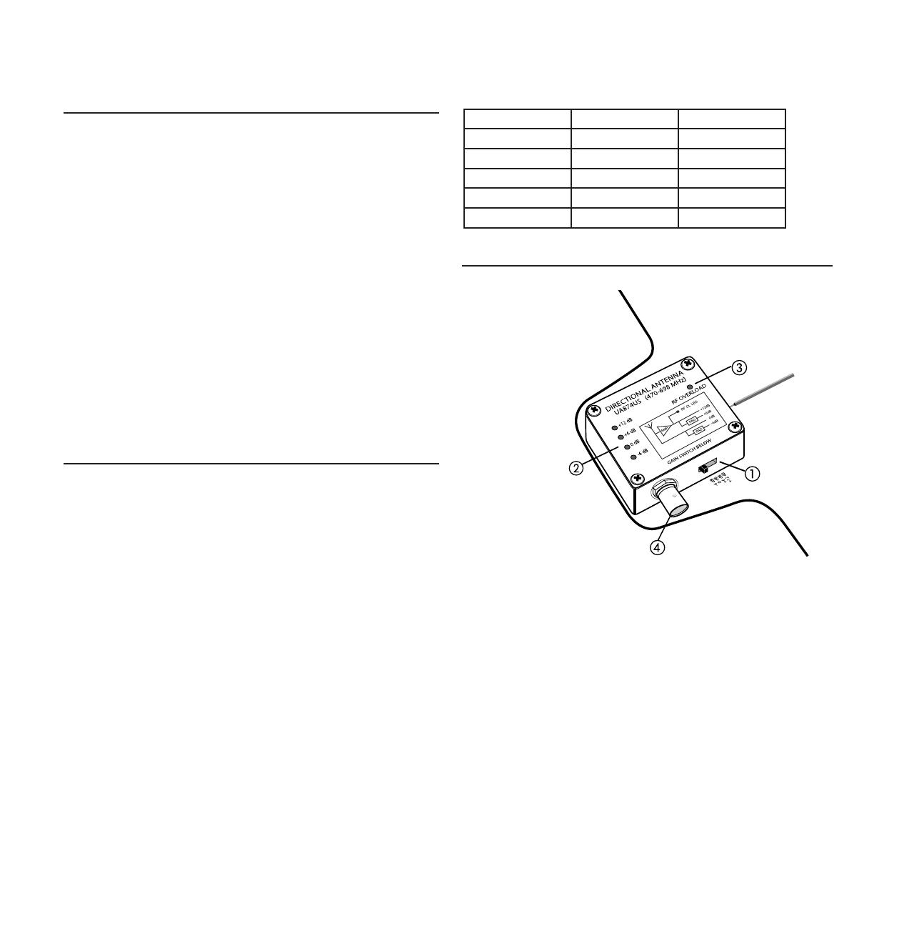
Interface
Gain Switch
Adjust the four-position gain switch to compensate for the calculated
cable loss, based on the length and type of cable.
Caution: There may be a small RF dropout when changing the gain
setting.
Gain Mode LED
Indicates the current gain switch setting.
RF Overload LED
Indicates a strong RF signal that is overloading the antenna amplifier,
which results in distortion or poor performance. Increase the distance
between the antenna and transmitter, or lower the antenna gain
setting.
NOTE: RF Overload LED does not operate for passive gain settings
(−6 dB or 0 dB).
BNC Connector
Connect to a reciever or antenna combiner with RF inputs that supply
10–15 V DC bias.
Installation
Connect the antenna to the receiver or distribution system using
Shure antenna cables (or any 50 ohm, low-loss coaxial cable, such as
RG-8U).
The antenna only operates with receivers or distribution systems that
provide 10–15 V DC bias.
Lower the gain setting for short cable runs, or increase gain for longer
runs. Note that the quality of the cable, not just the length, contributes
to signal loss. A lighter-grade 50 foot cable may require more gain than
a 100 foot, low-loss cable. Contact the cable manufacturer for cable
loss specifications.
Direct the antenna toward the intended coverage area.
Do not use this antenna for transmitting (such as with PSM
transmitters)
Cable Maintenance
To maintain top performance for UA825, UA850 or UA8100 antenna
cables:
Avoid sharp bends or kinks in the cables.
Do not deform cables with makeshift clamps, such as bending a nail
over the cable.
Do not use in permanent outdoor installations.
Do not expose to extreme moisture.
Antenna Cables from Shure
Shure offers the following pre-terminated antenna cables:
Length Type Model No.
6 foot RG58 UA806
10 foot RG58 PA725
25 foot RG8X UA825
50 foot RG213 UA850
100 foot RG213 UA8100
4
Antenna Placement
Use the following guidelines when mounting antennas:
Antennas and receivers must be from the same band.
Mount antennas at least four feet apart.
Position antennas so there is nothing obstructing a line of sight to the
transmitter (including the audience).
Keep antennas away from large metal objects.
Important: Always perform a "walk around" test to verify coverage before
using a wireless system during a speech or performance. Experiment
with antenna placement to find the optimum location. If necessary, mark
"trouble spots" and ask presenters or performers to avoid those areas.
Setting Gain
The gain setting should only be used to compensate for the calculated
cable signal loss. Additional signal gain does not mean better RF perfor-
mance. Too much gain actually reduces reception range and the number
of available channels. This is because Shure receivers are optimized to
deliver the best performance when the sum of signal gain and cable loss
equals 0 dB. Additional gain just amplifies everything in the RF range—in-
cluding interference and ambient RF noise. It cannot selectively increase
the signal from the transmitter.
Use the lowest gain setting necessary to achieve good reception of the
transmitter RF signal, as indicated on the receiver’s RF LED or meter.
Only increase the gain setting to compensate for the calculated cable
loss.
The −6 dB gain setting can be useful for applications with short cable
runs (25 feet or less) and where the distance between the transmitter
and antenna is less than 100 feet.
Reduce gain if the antenna RF Overload LED illuminates—the signal is
strong enough, so gain is not needed.
Recommend Gain Settings
Use the following chart as a guideline for setting gain based on cable type
where the distance from the antenna to the transmitter is greater than 100
feet.
NOTE: For installations where the antenna is less than 75 feet from the
transmitter, lower the gain setting one step.
Cable Length Gain Setting (based on cable type)
RG58* RG8X RG213/
RG8
Low-loss
RG8/
RG213**
10' (3 m) 0 0 0 0
25' (8 m) +6* 0 0 0
50' (15 m) * +6 +6 0
100' (30 m) * +12 +6 +6
* RG58 cable has high signal loss and is not recommended for cable
runs greater than 10 feet
** Low-loss RG8/RG213 cables include Times Microwave Systems
LMR400 and Belden 9913 or 7810A
Find More Information Online
For setup tips and more information on wireless accessories, visit http://
www.shure.com/WirelessAccessoryWizard
Optional Accessories
Protective zipper pouch WA874ZP
15.35 in
14.33 in
390 mm
364 mm
5
Certifications
Meets essential requirements of the following European Directives:
R&TTE Directive 99/5/EC
WEEE Directive 2002/96/EC, as amended by 2008/34/EC
RoHS Directive 2002/95/EC, as amended by 2008/35/EC
Note: Please follow your regional recycling scheme for batteries and
electronic waste
Meets requirements of the following standards: EN60065, EN 301 489
Parts 1 and 9.
The CE Declaration of Conformity can be obtained from Shure
Incorporated or any of its European representatives. For contact informa-
tion please visit www.shure.com
The CE Declaration of Conformity can be obtained from: www.shure.com/
europe/compliance
Authorized European representative:
Shure Europe GmbH
Headquarters Europe, Middle East & Africa
Department: EMEA Approval
Jakob-Dieffenbacher-Str. 12
75031 Eppingen, Germany
Phone: 49-7262-92 49 0
Fax: 49-7262-92 49 11 4
Specifications
Connector Type
BNC, Female
Impedance
50 Ω
Power Requirements
10 to 15 V DC bias from coaxial connection, 75 mA
RF Frequency Range
UA874US
470–698 MHz
UA874E
470–790 MHz
UA874WB
470–900 MHz
UA874X
925–952 MHz
Reception Pattern
3 dB Beam Width
70 degrees
Third-order Overload Intercept Point (OIP3)
>30 dBm
Antenna Gain
On Axis
7.5dBi
Signal Gain
±1 dB, Switchable
+12 dB
+6 dB
0 dB
−6 dB
RF Overload LED Threshold
−5 dBm
RF overload LED does not operate for passive gain settings
Dimensions
UA874
316 x 359 x 36 mm (H x W x D)
UA874X
224 x 234 x 36 mm (H x W x D)
Weight
UA874
317 g (11.2 oz.)
UA874X
213 g (7.5 oz.)
Operating Temperature Range
−18°C (0°F) to 63°C (145°F)
Storage Temperature Range
−29°C (-20°F) to 74°C (165°F)
35
认证
符合下列欧盟指令的基本要求:
R&TTE 指令 99/5/EC
2008/34/EC 修订的 WEEE 指导原则 2002/96/EC
2002/95/EC 修订的 RoHS 指导原则 2002/95/EC
注意: 请遵循您所在地的电池和电子废弃物回收方案
符合下列标准的要求: EN60065, EN 301,489 第 1 章和第 9 章.
可从舒尔公司或其任何欧洲代表处获得“欧盟符合性声明”。有关联系信息,
请访问 www.shure.com
可从以下地址获得“CE 符合性声明”:www.shure.com/europe/compliance
授权的欧洲代表:
Shure Europe GmbH
欧洲、中东、非洲总部
部门:欧洲、中东、非洲批准部
Jakob-Dieffenbacher-Str.12
75031 Eppingen, Germany
电话:49-7262-92 49 0
传真:49-7262-92 49 11 4
电子邮件:[email protected]
规格
接头类型
BNC, 插孔
阻抗
50 Ω
电源要求
来自同轴连接的 10 至 15 伏直流偏移, 75 mA
射频频率范围
UA874US
470–698 MHz
UA874E
470–790 MHz
UA874WB
470–900 MHz
UA874X
925–952 MHz
接收模式
3 dB 波束宽度
70 角度
三阶过载交截点 (OIP3)
>30 dBm
天线增益
在轴
7.5dBi
信号增益
±1 dB, 可切换
+12 dB
+6 dB
0 dB
−6 dB
射频信号过强指示灯阈值
−5 dBm
射频信号过载指示灯无法在无源增益设置下工作
外观尺寸
UA874
316 x 359 x 36 毫米 (高度 x 宽度 x 深度)
UA874X
224 x 234 x 36 毫米 (高度 x 宽度 x 深度)
重量
UA874
317 克 (11.2 盎司)
UA874X
213 克 (7.5 盎司)
工作温度范围
−18°C (0°F) 到 63°C (145°F)
存储温度范围
−29°C (-20°F) 到 74°C (165°F)
选配附件
保护的拉链袋 WA874ZP
15.35 in
14.33 in
390 mm
364 mm
38
認證
符合下列歐盟指令的基本要求:
R&TTE 指令 99/5/EC
2008/34/EC 修訂的 WEEE 指令 2002/96/EC
請遵循您所在地的電子廢棄物回收方案
2008/35/EC 修訂的 RoHS 指令 2002/95/EC
符合下列標準的要求:EN60065, EN 301 489 第 1 章和第 9 章.
可從舒爾公司或其任何歐洲代表處獲得“歐盟符合性聲明”。 有關聯繫資
訊,請存取 www.shure.com
可從以下地址獲得“CE 符合性聲明”:www.shure.com/europe/compliance
歐盟授權代表:
Shure Europe GmbH
歐洲、中東、非洲總部
部門:歐洲、中東、非洲批准部
Jakob-Dieffenbacher-Str.12
75031 Eppingen, Germany
電話:49-7262-92 49 0
傳真:49-7262-92 49 11 4
電子郵件:[email protected]
規格
接头类型
BNC, 插孔
阻抗
50 Ω
電源要求
來自同軸連接的 10 至 15 伏直流偏移, 75 mA
頻率範圍
UA874US
470–698 MHz
UA874E
470–790 MHz
UA874WB
470–900 MHz
UA874X
925–952 MHz
接收模式
3 dB 波束寬度
70 度
三階過載交截點 (OIP3)
>30 dBm
天線增益
在軸
7.5dBi
訊號增益
±1 dB, 可切換
+12 dB
+6 dB
0 dB
−6 dB
RF 訊號過強指示燈閾值
−5 dBm
RF 訊號過強指示燈無法在無源增益設定下工作
外觀尺寸
UA874
316 x 359 x 36 毫米 (高度 x 寬度 x 深度)
UA874X
224 x 234 x 36 毫米 (高度 x 寬度 x 深度)
重量
UA874
317 克 (11.2 盎司)
UA874X
213 克 (7.5 盎司)
工作溫度範圍
−18°C (0°F) 到 63°C (145°F)
存儲溫度範圍
−29°C (-20°F) 到 74°C (165°F)
可選配件
保護的拉鍊袋 WA874ZP
15.35 in
14.33 in
390 mm
364 mm
PT. GOSHEN SWARA INDONESIA
Kompleks Harco Mangga Dua Blok L No. 35 Jakarta Pusat
I.16.GSI31.00501.0211
Europe, Middle East, Africa:
Shure Europe GmbH
Jakob-Dieffenbacher-Str. 12,
75031 Eppingen, Germany
Phone: 49-7262-92490
Fax: 49-7262-9249114
  • Page 1 1
  • Page 2 2
  • Page 3 3
  • Page 4 4
  • Page 5 5
  • Page 6 6
  • Page 7 7
  • Page 8 8
  • Page 9 9
  • Page 10 10
  • Page 11 11
  • Page 12 12
  • Page 13 13
  • Page 14 14
  • Page 15 15
  • Page 16 16
  • Page 17 17
  • Page 18 18
  • Page 19 19
  • Page 20 20
  • Page 21 21
  • Page 22 22
  • Page 23 23
  • Page 24 24
  • Page 25 25
  • Page 26 26
  • Page 27 27
  • Page 28 28
  • Page 29 29
  • Page 30 30
  • Page 31 31
  • Page 32 32
  • Page 33 33
  • Page 34 34
  • Page 35 35
  • Page 36 36
  • Page 37 37
  • Page 38 38
  • Page 39 39
  • Page 40 40
  • Page 41 41
  • Page 42 42
  • Page 43 43
  • Page 44 44

Shure UA874 User manual

Category
Television antennas
Type
User manual

Ask a question and I''ll find the answer in the document

Finding information in a document is now easier with AI