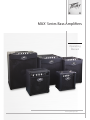
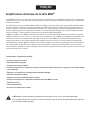
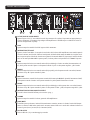
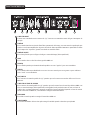
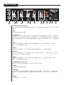
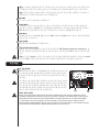
Peavey MAX 126 10-Watt Bass Amp Combo Owner's manual
- Category
- Musical Instrument Amplifier
- Type
- Owner's manual

www.peavey.com
MAX
®
Series Bass Ampliers
Operating
Manual

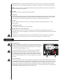
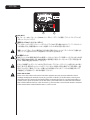
Intended to alert the user to the presence of uninsulated “dangerous voltage” within the product’s enclosure that may be of sufcient magnitude to constitute
a risk of electric shock to persons.
Intended to alert the user of the presence of important operating and maintenance (servicing) instructions in the literature accompanying the product.
CAUTION: Risk of electrical shock — DO NOT OPEN!
CAUTION: To reduce the risk of electric shock, do not remove cover. No user serviceable parts inside. Refer servicing to qualied service personnel.
WARNING: To prevent electrical shock or re hazard, this apparatus should not be exposed to rain or moisture‚ and objects lled with liquids‚ such as vases‚
should not be placed on this apparatus. Before using this apparatus‚ read the operating guide for further warnings.
Protective earthing terminal. The apparatus should be connected to a mains socket outlet with a protective earthing connection.
SPANISHENGLISH
FINNISH
FRENCH
GERMAN
Tarkoitettu kiinnittämään käyttäjän huomio sellaiseen eristämättömään vaaralliseen jännitteeseen tuotteen kotelossa, joka saattaa olla riittävän suuri
aiheuttaakseen sähköiskuvaaran.
Tarkoitettu kiinnittämään käyttäjän huomio tärkeisiin käyttö- ja huolto-ohjeisiin tuotteen mukana seuraavassa ohjeistuksessa.
VAROITUS: Sähköiskun vaara — ÄLÄ AVAA!
VAROITUS: Sähköiskuvaaran vuoksi älä poista kantta. Ei sisällä käyttäjän huollettavissa olevia osia. Huoltaminen tulee jättää pätevän huoltohenkilöstön
tehtäväksi.
VAARA: Sähköiskun tai tulipalon vaaran estämiseksi tätä laitetta ei saa altistaa sateelle tai kosteudelle, eikä sen päälle saa asettaa nesteellä täytettyjä
esineitä, kuten maljakoita. Ennen laitteen käyttöä lue muut varoitukset käyttöohjeesta.
Suojamaadoitus terminaali. Laite tulee kytkeä sähköverkkoon suojajohtimella.
Laite on liitettävä suojamaadoituskoskettimilla varustettuun pistorasiaan.
Ce symbole est utilisé dans ce manuel pour indiquer à l’utilisateur la présence d’une tension dangereuse pouvant être d’amplitude sufsante pour constituer
un risque de choc électrique.
Ce symbole est utilisé dans ce manuel pour indiquer à l’utilisateur qu’il ou qu’elle trouvera d’importantes instructions concernant l’utilisation et l’entretien de
l’appareil dans le paragraphe signalé.
ATTENTION: Risques de choc électrique — NE PAS OUVRIR!
ATTENTION: An de réduire le risque de choc électrique, ne pas enlever le couvercle. Il ne se trouve à l’intérieur aucune pièce pouvant être reparée par
l’utilisateur. Conez I’entretien et la réparation de l’appareil à un réparateur Peavey agréé.
AVIS: Dans le but de reduire les risques d’incendie ou de decharge electrique, cet appareil ne doit pas etre expose a la pluie ou a l’humidite et aucun objet
rempli de liquide, tel qu’un vase, ne doit etre pose sur celui-ci. Avant d’utiliser de cet appareil, lisez attentivement le guide fonctionnant pour avertissements
supplémentaires.
Borne de terre de protection. L'appareil doit être connecté à une prise secteur avec une connexion à la terre.
Dieses Symbol soll den Anwender vor unisolierten gefährlichen Spannungen innerhalb des Gehäuses warnen, die von Ausreichender Stärke sind, um einen
elektrischen Schlag verursachen zu können.
Dieses Symbol soll den Benutzer auf wichtige Instruktionen in der Bedienungsanleitung aufmerksam machen, die Handhabung und Wartung des Produkts
betreffen.
VORSICHT: Risiko — Elektrischer Schlag! Nicht öffnen!
VORSICHT: Um das Risiko eines elektrischen Schlages zu vermeiden, nicht die Abdeckung enfernen. Es benden sich keine Teile darin, die vom Anwender
repariert werden könnten. Reparaturen nur von qualiziertem Fachpersonal durchführen lassen.
WARNUNG: Um elektrischen Schlag oder Brandgefahr zu verhindern, sollte dieser Apparat nicht Regen oder Feuchtigkeit ausgesetzt werden und
Gegenstände mit Flüssigkeiten gefuellt, wie Vasen, nicht auf diesen Apparat gesetzt werden. Bevor dieser Apparat verwendet wird, lesen Sie bitte den
Funktionsführer für weitere Warnungen.
Schutzerdung Terminal. Das Gerät nur an Steckdose mit Schutzleiter angeschlossen werden.
Este símbolo tiene el propósito, de alertar al usuario de la presencia de “(voltaje) peligroso” sin aislamiento dentro de la caja del producto y que puede tener
una magnitud suciente como para constituir riesgo de descarga eléctrica.
Este símbolo tiene el propósito de alertar al usario de la presencia de instruccones importantes sobre la operación y mantenimiento en la información que
viene con el producto.
PRECAUCION: Riesgo de descarga eléctrica ¡NO ABRIR!
PRECAUCION: Para disminuír el riesgo de descarga eléctrica, no abra la cubierta. No hay piezas útiles dentro. Deje todo mantenimiento en manos del
personal técnico cualicado.
ADVERTENCIA: Para prevenir choque electrico o riesgo de incendios, este aparato no se debe exponer a la lluvia o a la humedad. Los objetos llenos de
liquidos, como los oreros, no se deben colocar encima de este aparato. Antes de usar este aparato, lea la guia de funcionamiento para otras advertencias.
Terminal de puesta a tierra de protección. El aparato debe estar conectado a una toma de corriente con conexión a tierra de protección.
Page is loading ...
Page is loading ...

ENGLISH
IMPORTANT SAFETY INSTRUCTIONS
WARNING: When using electrical products, basic cautions should always be followed, including the following:
1. Read these instructions.
2. Keep these instructions.
3. Heed all warnings.
4. Follow all instructions.
5. Do not use this apparatus near water.
6. Clean only with a dry cloth.
7. Do not block any of the ventilation openings. Install in accordance with manufacturer’s instructions.
8. Do not install near any heat sources such as radiators, heat registers, stoves or other apparatus (including amplifiers) that
produce heat.
9. Do not defeat the safety purpose of the polarized or grounding-type plug. A polarized plug has two blades with one wider than
the other. A grounding type plug has two blades and a third grounding plug. The wide blade or third prong is provided for your
safety. If the provided plug does not fit into your outlet, consult an electrician for replacement of the obsolete outlet.
10. Protect the power cord from being walked on or pinched, particularly at plugs, convenience receptacles, and the point they exit
from the apparatus.
11. Only use attachments/accessories provided by the manufacturer.
12. Use only with a cart, stand, tripod, bracket, or table specified by the manufacturer, or sold with the apparatus. When a cart is
used, use caution when moving the cart/apparatus combination to avoid injury from tip-over.
13. Unplug this apparatus during lightning storms or when unused for long periods of time.
14. Refer all servicing to qualified service personnel. Servicing is required when the apparatus has been damaged in any way, such
as power-supply cord or plug is damaged, liquid has been spilled or objects have fallen into the apparatus, the apparatus has
been exposed to rain or moisture, does not operate normally, or has been dropped.
15. Never break off the ground pin. Write for our free booklet “Shock Hazard and Grounding.” Connect only to a power supply of the
type marked on the unit adjacent to the power supply cord.
16. If this product is to be mounted in an equipment rack, rear support should be provided.
17. Note for UK only: If the colors of the wires in the mains lead of this unit do not correspond with the terminals in your plug‚
proceed as follows: a) The wire that is colored green and yellow must be connected to the terminal that is marked by the letter
E‚ the earth symbol‚ colored green or colored green and yellow. b) The wire that is colored blue must be connected to the
terminal that is marked with the letter N or the color black. c) The wire that is colored brown must be connected to the terminal
that is marked with the letter L or the color red.
18. This electrical apparatus should not be exposed to dripping or splashing and care should be taken not to place objects
containing liquids, such as vases, upon the apparatus.
19. The on/off switch in this unit does not break both sides of the primary mains. Hazardous energy can be present inside the
chassis when the on/off switch is in the off position. The mains plug or appliance coupler is used as the disconnect device, the
disconnect device shall remain readily operable.
20. Exposure to extremely high noise levels may cause a permanent hearing loss. Individuals vary considerably in susceptibility to
noise-induced hearing loss, but nearly everyone will lose some hearing if exposed to sufficiently intense noise for a sufficient
time. The U.S. Government’s Occupational Safety and Health Administration (OSHA) has specified the following permissible
noise level exposures:
Duration Per Day In Hours Sound Level dBA, Slow Response
8 90
6 92
4 95
3 97
2 100
1 1⁄2 102
1 105
1⁄2 110
1⁄4 or less 115
According to OSHA, any exposure in excess of the above permissible limits could result in some hearing loss. Earplugs or protectors to
the ear canals or over the ears must be worn when operating this amplification system in order to prevent a permanent hearing loss, if
exposure is in excess of the limits as set forth above. To ensure against potentially dangerous exposure to high sound pressure levels, it is
recommended that all persons exposed to equipment capable of producing high sound pressure levels such as this amplification system be
protected by hearing protectors while this unit is in operation.
SAVE THESE INSTRUCTIONS!
Page is loading ...
Page is loading ...
Page is loading ...
Page is loading ...
Page is loading ...

Correct Disposal of this product. This marking indicates that this
product should not be disposed with other house hold wastes
throughout the EU. To prevent possible harm to the environment or
human health from uncontrolled waste disposal, recycle it responsibly
to promote the sustainable reuse of material resources. To return your
used device, please use the return and collection systems, or contact
the retailer where the product was purchased. They can take this
product for environmental safe recycling.
Logo referenced in Directive 2002/96/EC Annex
I(OJ(L)37/38,13.02.03 and dened in EN 50419: 2005
The bar is the symbol for marking of new waste and is applied
only to equipment manufactured after 13 August 2005
Forma correcta de deshacerse de este producto. Esta marca indica que este producto
no debe arrojarse junto con otros desperdicios domésticos en ningún lugar de la Unión
Europea. Para evitar posibles daños al medio ambiente o a la salud humana debidos a
desechos no controlados de desperdicios, recíclelo responsablemente para promover
la reutilización sostenible de los recursos materiales. Para devolver su dispositivo
usado, utilice los sistemas de devolución recolección, o contacte con el vendedor
minorista donde compró el producto. Ellos pueden llevar este producto al reciclado
seguro para el medio ambiente.
Logotipo al que se hace referencia en la Directiva 2002/96/EC
AnexoIV(OJ(L)37/38,13.02.03 y denido en EN 50419: 2005
La barra es el símbolo para marcar los nuevos desechos y se aplica
solamente a equipamiento fabricado después del 13 de agosto de 2005
Recyclez correctement ce produit. Cette signalisation indique que ce produit ne
doit pas être jeté avec les autres déchets domestiques dans les pays de l’UE. Pour
éviter toute atteinte à l’environnement ou à la santé humaine par des décharges
sauvages, recyclez ce produit de manière responsable pour encourager la
réutilisation durable des ressources matérielles. Pour retourner votre appareil usé,
veuillez utiliser les systèmes de collecte et de retour, ou contactez le revendeur
à qui vous avez acheté le produit. Il prendra en charge ce produit de manière à
protéger l’environnement.
Logo documenté dans l’annexe de la Directive 2002/96/EC
IV_(OJ(L)37/38,13.02.03 et déni par la norme EN 50419:2005
La barre est le symbole de signalisation des nouveaux déchets qui
s’applique uniquement aux équipements fabriqués après le 13 août 2005
Tuotteen oikea hävittäminen. Tämä merkki ilmaisee, että tuotetta ei saa hävittää muun
talousjätteen mukana EU:n alueella. Jotta estetään mahdolliset valvomattoman jätteiden
hävittämisen haitat ympäristölle tai ihmisten terveydelle, kierrätä tuote vastuullisesti ja
edistä materiaalien kestävää uudelleenkäyttöä. Voit palauttaa käytetyn laitteen käyttämällä
keräysjärjestelmiä tai ottamalla yhteyttä jälleenmyyjään, jolta laite ostettiin. He voivat
toimittaa tuotteen ympäristön kannalta turvalliseen kierrätykseen.
Logo viitattu direktiivin 2002/96/EY liitteen
IV(OJ(L)37/38,13.02.03 mukaisesti, määritelty standardissa EN 50419: 2005
Palkki on uuden jätteen merkintäsymboli ja sitä käytetään vain 13. elokuuta
2005 jälkeen valmistetuissa laitteissa
Juiste verwijdering van dit product. Deze markering geeft aan dat dit product
nergens in de Europese Unie met ander huishoudelijk afval mag worden afgevoerd.
Om mogelijke schade aan het milieu of gezondheid door ongecontroleerde
afvalverwijdering te voorkomen, recycle het op een verantwoorde wijze om het
duurzame hergebruik van materiaalgrondstoffen te bevorderen. Om uw gebruikte
apparaat in te leveren, kunt u gebruik maken van de inlever- en verzamelsystemen
of contact opnemen met de verkoper waar het product is gekocht. Zij kunnen dit
product innemen voor het milieuvriendelijk recycling.
Het logo waarnaar wordt verwezen in de bijlage van Richtlijn 2002/96/EG
IV(OJ(L)37/38,13.02.03 en omschreven in EN 50419: 2005
De balk is het symbool voor het markeren van nieuw afval en wordt
alleen toegepast op apparatuur dat is vervaardigd na 13 augustus 2005
正确处理此产品。此标志表明该产品在整个欧盟区内不应该与其他家居生
活废弃物一同处置。为防止因无控废弃物处置对环境或人类健康可能造成
的危害,请负责地回收并促进可重复使用的物质资源。要返还旧设备,请
使用退返收集系统,或联系购买此产品的零售商。他们会为环境安全回收
此产品。
标志参照 2002/96/EC 指令附录
IV(OJ(L)37/38,13.02.03 和 EN 50419: 2005 定义
条码符号标示新废弃物,仅适用于 2005 年 8 月 13 日后生产的设备
Entsorgen Sie dieses Produkt umweltgerecht. Diese Kennzeichnung bedeutet,
dass das Produkt innerhalb der EU nicht mit dem Hausmüll entsorgt werden darf.
Zur Vermeidung von Umwelt- und Gesundheitsschäden durch unkontrollierte
Entsorgung recyceln Sie das Gerät bitte. Geben Sie das Gerät an einer Sammelstelle
für Elektroaltgeräte ab oder wenden Sie sich an Ihren Fachhändler.
Logo eingetragen in Richtlinie 2002/96/EC AnhangI
IV_(OJ(L)37/38, 13.02.03 und deniert in EN 50419: 2005
Der Balken ist das Symbol zur Kennzeichnung neuen Abfalls und wird nur
auf Geräten angebracht, die nach dem 13. August 2005 gefertigt wurden
Korrekt bortskaffande av denna produkt. Denna märkning betyder att
produkten inte skall bortskaffas tillsammans med annat hushållsavfall i
hela EU. För att förhindra eventuella skador för miljön eller människors
hälsa från okontrollerat bortskaffande av avfall, återvinn det ansvarsfullt för
att främja hållbar återanvändning av materiella resurser. För att returnera
din använda enhet, använd återanvändnings- och uppsamlingssystem,
eller kontakta den återförsäljare där produkten köptes. De kan ta hand om
denna produkt för miljösäker återvinning.
Logotyp som hänvisas till i direktiv 2002/96/EG bilaga
IV(OJ(L)37/38,13.02.03 och denieras i EN 50419: 2005
Stapeln är symbolen för märkning av nytt avfall och är endast
tillämplig på utrustning som tillverkats efter 13 augusti, 2005
Corretto smaltimento di questo prodotto. Questo simbolo indica che questo prodotto
non deve essere smaltito insieme ad altri riuti domestici in tutta Europa. Per
prevenire possibili danni all’ambiente o alla salute umana dovuti allo smaltimento non
regolamentato dei riuti, è necessario riciclarlo responsabilmente al ne di promuovere
il riutilizzo sostenibile delle risorse materiali. Per restituire il dispositivo usato, utilizzare
i sistemi di restituzione e raccolta o contattare il rivenditore presso il quale il prodotto è
stato acquistato. Quest’ultimo può occuparsi del riciclaggio ambientale sicuro di questo
prodotto.
Simbolo presente nell’allegato IV_(OJ(L)37/38,13.02.03 della direttiva 2002/96/
CE e denito nello standard EN 50419: 2005
La barra è il simbolo indicante un nuovo riuto ed è applicata esclusivamente ad
apparecchiature prodotte successivamente al 13 agosto 2005
Page is loading ...
Page is loading ...
Page is loading ...
Page is loading ...
Page is loading ...
Page is loading ...
Page is loading ...
Page is loading ...

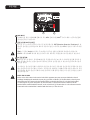
FCC Compliancy Statement
This device complies with Part 15 of the FCC rules. Operation is subject to the following two
conditions: (1) this device may not cause harmful interference, and (2) this device must accept any
interference received, that may cause undesired operation.
Warning: Changes or modications to the equipment not approved by Peavey Electronics Corp. can
void the user’s authority to use the equipment.
Note - This equipment has been tested and found to comply with the limits for a Class B digital device,
pursuant to Part 15 of the FCC Rules. These limits are designed to provide reasonable protection
against harmful interference in a residential installation. This equipment generates, uses and can radiate
radio frequency energy and, if not installed and used in accordance with the instructions, may cause
harmful interference to radio communications. However, there is no guarantee that interference will not
occur in a particular installation. If this equipment does cause harmful interference to radio or television
reception, which can be determined by turning the equipment off and on, the user is encouraged to try
and correct the interference by one or more of the following measures.
• Reorient or relocate the receiving antenna.
• Increase the separation between the equipment and receiver.
• Connect the equipment into an outlet on a circuit different from that to which the receiver is connected.
• Consult the dealer or an experienced radio/TV technician for help.
Peavey Electronics Corporation • 5022 Hartley Peavey Drive • Meridian, MS • 39305
(601) 483-5365 • FAX (601) 486-1278 • www.peavey.com • 80305796

ENGLISH
VENTILATION: For proper ventilation, allow 12" clearance from the nearest combustible surface.
All vents should have a minimum of 2" of free air space so air can flow thru the unit freely for proper cooling.
MAX
®
Series Bass Amplifiers
The Peavey MAX
®
Series is designed for superior tone, performance and reliability in portable bass amplification, with power
ratings up to 300 watts of power with Peavey’s DDT
™
speaker protection and exclusive tone enhancements.
The Peavey MAX 115, MAX 112 and MAX 110 bass combo amps deliver huge bass tone with exclusive Peavey designs, including
unique psycho-acoustic low-end enhancement that adds bass without demanding anything extra from the speaker—a
testament to Peavey's technology-driven reliability. The EQ section includes three-band EQ, a gain boost featuring Peavey’s
patented TransTube
®
tube emulation circuitry, and switchable presets like Punch, Mid-Shift and Bright.
The MAX 115, MAX 112 and MAX 110 also feature a built-in chromatic tuner with mute, a tuned and ported enclosure, 1/8"
headphone output and 1/8" auxiliary input. The MAX 115 and MAX 112 include an XLR direct output with ground lift, while
the MAX 115 has a built-in tweeter that is bypassed when the TransTube
gain boost is engaged for a more authentic classic
overdrive sound.
The MAX 158 and MAX 126 practice amps are loaded with features that make them ideal for small rehearsals, including
TransTube
gain boost, multi-band EQ, exclusive DDT
™
compression, headphone output and auxiliary input. The MAX 158 also
includes psycho-acoustic low end enhancement and built-in chromatic tuner with mute.
Features: (vary according to model)
• Up to 300 watts of power
• Premium speakers
• DDT
™
speaker protection
• Pre-gain control with TransTube
®
gain boost which bypasses the tweeter for more authentic classic tone
• Three-band EQ with Punch, Mid-Shift and Bright controls
• Tuned, ported enclosures
• Psycho-acoustic low-end enhancement
• Built-in direct output with ground lift (MAX 115 & 112)
• 1/8" aux input
• 1/8" headphones output
• Chromatic tuner with mute

3
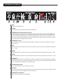
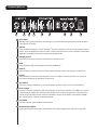
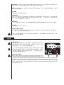
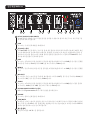
DIRECT INTERFACE (DI)
This is a built-in, balanced Direct Interface that sends a buered, unprocessed signal to an external mixer.
GROUND LIFT: This button is provided to prevent a ground loop that may result in "hum" noise. When
depressed (IN position), Ground Lift is engaged.
ACTIVE/PASSIVE PICKUP Inputs
These 1/4" inputs are included so you can choose the appropriate setting for your instrument. The gain
structure of the amplier is modied to accommodate the outputs of dierent pickup congurations.
GAIN
This knob controls input level of the instrument.
TT BOOST SWITCH
This TransTube
®
crunch circuit is designed so that the volume of the amp will not change when the boost
is switched on, but the distortion level will increase depending on the level of the GAIN knob. For best
results, rst set the distortion amount by adjusting the GAIN. Next, set the desired volume using the VOL-
UME knob. At this point, the clean volume will match if the TT BOOST is turned o.
PUNCH
This switch engages a boost of 6dB at 100Hz, which greatly enhances the low-end presence of the bass
guitar.
BASS
This knob provides a shelving tone control for low frequencies and provides cut/boost of +/-15 dB. The
center point is at. The center frequency is 50 Hz. -3 dB shelf corner frequency is 100Hz.
MIDDLE
This knob provides a peaking tone control for Mid frequencies and cut/boost of +/-15dB. The center point
is at.
MID SHIFT
This switch controls the center frequency of the MIDDLE knob. When the switch is OUT, the middle fre-
quency is 600Hz. The middle frequency is 250Hz when the switch is pushed IN.
TREBLE
This knob provides a shelving tone control for high frequencies and cut/boost of +/-15dB. The center
point is at and the frequency is 8 KHz. -3dB; the shelf corner frequency is 5 KHz.
BRIGHT SWITCH
This button provides a 10 dB boost to frequencies above 1KHz. To activate, depress the switch to its “IN”
position.
PSYCHO-ACOUSTICS EFFECT SWITCH
The human ear does not hear low frequencies as well as higher frequencies. This means that as bass
goes lower, more and more power is required. The MAX
®
Psycho-Acoustics eect solves this problem by
identifying extremely low notes, generating harmonics based on the notes, and then blending the har-
monics with the original note, making the lows seem louder and tighter without eating up excess power
amp headroom.
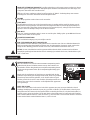
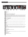
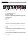
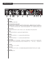
Front Panel MAX
®
115 and 112
1
2
3
4
5
6
7
8
9
10
1 7 8
15
9
42
11
5
6
12
1410
11
16
13

Rear Panel
THE BOTTOM LINE: using the eect will make the lowest notes you can possibly play sound unbeliev-
ably loud and clear. Practice with headphones is no longer a compromise. It even works with chords!
HINT: For best results, try using the eect without boosting the LOW control to extreme settings. This
will make the eect more apparent.
VOLUME
This knob controls the overall volume of the amplier.
TUNE/MUTE
Pressing this button will engage the chromatic tuner while muting the output to the speaker. The LED
screen will indicate which note is being played while the red and green LEDs above the screen indicate
whether the note is at (red), sharp (red) or in tune (green). This switch also mutes the DI.
AUX INPUT
This 1/8" input jack allows you to connect a CD player or MP3 player to your MAX Series bass amp
and play along
HEADHPHONE OUTPUT
1/8" headphone output for personal monitoring.
POWER SWITCH/DDT
™
INDICATOR LIGHT
This dual-purpose switch is used to turn the amp on and o. When the DDT (Distortion Detection
Technique) senses power amp clipping, a protection circuit is engaged and the LEDs in the power switch
change to red.
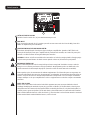
CAUTION: The on/o switch in this unit does not break both sides of the primary mains. Hazardous
energy can be present inside the chassis even when the on/o switch is in the OFF position.
AC POWER INLET:
This is the receptacle for an IEC line cord, which provides AC power to
the unit. Connect the line cord to this connector to provide power to the
unit. Damage to the equipment may result if improper line voltage is
used. (See line voltage marking on unit).
Never break o the ground pin on any equipment. It is provided for
your safety. If the outlet used does not have a ground pin, a suit-
able grounding adapter should be used, and the third wire should be
grounded properly. To prevent the risk of shock or re hazard, always
make sure that the amplier and all associated equipment is properly
grounded.
NOTE: FOR UK ONLY
As the colors of the wires in the mains lead of this apparatus may not correspond with the colored mark-
ings identifying the terminals in your plug, proceed as follows: (1) The wire that is colored green and yel-
low must be connected to the terminal that is marked by the letter E, or by the Earth symbol, or colored
green or green and yellow. (2) The wire that is colored blue must be connected to the terminal that is
marked with the letter N, or the color black. (3) The wire that is colored brown must be connected to the
terminal that is marked with the letter L, or the color red.
12
13
14
17
17
18
15
16
18

3
ACTIVE/PASSIVE PICKUP INPUTS
These 1/4" inputs are included so you can choose the appropriate setting for your instrument. The gain
structure of the amplier is modied to accommodate the outputs of dierent pickup congurations.
GAIN
This knob controls input level of the instrument.
TT BOOST SWITCH
This TransTube
®
crunch circuit is designed so that the volume of the amp will not change when the boost
is switched on, but the distortion level will increase depending on the level of the GAIN knob. For best
results, rst set the distortion amount by adjusting the GAIN. Next, set the desired volume using the VOL-
UME knob. At this point, the clean volume will match if the TT BOOST is turned o.
BASS
This knob provides a shelving tone control for low frequencies and provides cut/boost of +/-15 dB. The
center point is at. The center frequency is 50 Hz. -3 dB shelf corner frequency is 100Hz.
MIDDLE
This knob provides a peaking tone control for Mid frequencies and cut/boost of +/-15dB. The center point
is at.
MID SHIFT
This switch controls the center frequency of the MIDDLE knob. When the switch is OUT, the middle fre-
quency is 600Hz. The middle frequency is 250Hz when the switch is pushed IN.
TREBLE
This knob provides a shelving tone control for high frequencies and cut/boost of +/-15dB. The center
point is at and the frequency is 8 KHz. -3dB; the shelf corner frequency is 5 KHz.
PSYCHO-ACOUSTICS EFFECT SWITCH
See Psyco-acoustics eect switch description on page 9.
VOLUME
This knob controls the overall volume of the amplier.
TUNE/MUTE
Pressing this button will engage the chromatic tuner while muting the output to the speaker. The LED
screen will indicate which note is being played while the red and green LEDs above the screen indicate
whether the note is at (red), sharp (red) or in tune (green).
HEADHPHONE OUTPUT
1/8" headphone output for personal monitoring.
Front Panel MAX
®
110
1
2
3
4
5
6
7
8
9
10
1
8
9
42 7
11
5 6
12
13
10
11

Rear Panel
AUX INPUT
This 1/8" input jack allows you to connect a CD player or MP3 player to your MAX
®
Series bass amp
and play along
POWER SWITCH/DDT
™
INDICATOR LIGHT
This dual-purpose switch is used to turn the amp on and o. When the DDT (Distortion Detection
Technique) senses power amp clipping, a protection circuit is engaged and the LEDs in the power switch
change to red.
CAUTION: The on/o switch in this unit does not break both sides of the primary mains. Hazardous
energy can be present inside the chassis even when the on/o switch is in the OFF position.
AC POWER INLET:
This is the receptacle for an IEC line cord, which provides AC power to the unit. Connect the line cord to
this connector to provide power to the unit. Damage to the equipment may result if improper line volt-
age is used. (See line voltage marking on unit).
Never break o the ground pin on any equipment. It is provided for your safety. If the outlet used does
not have a ground pin, a suitable grounding adapter should be used, and the third wire should be
grounded properly. To prevent the risk of shock or re hazard, always make sure that the amplier and
all associated equipment is properly grounded.
NOTE: FOR UK ONLY
As the colors of the wires in the mains lead of this apparatus may not correspond with the colored mark-
ings identifying the terminals in your plug, proceed as follows: (1) The wire that is colored green and yel-
low must be connected to the terminal that is marked by the letter E, or by the Earth symbol, or colored
green or green and yellow. (2) The wire that is colored blue must be connected to the terminal that is
marked with the letter N, or the color black. (3) The wire that is colored brown must be connected to the
terminal that is marked with the letter L, or the color red.Putet, quisci tisl et adionsenibh esequi ting et
12
13
14
14
15
15

3
INPUT
1/4" input jack.
VOLUME
This knob controls the volume of the amplier.
PSYCHO-ACOUSTICS EFFECT SWITCH
The human ear does not hear low frequencies as well as higher frequencies. This means that as bass
goes lower, more and more power is required. The MAX
®
Psycho-Acoustics eect solves this problem by
identifying extremely low notes, generating harmonics based on the notes, and then blending the har-
monics with the original note, making the lows seem louder and tighter without eating up excess power
amp headroom.
TT Boost SWITCH
This button engages a TransTube
®
crunch eect, simulating the classic overdriven tube amp sound.
BASS
This knob provides a shelving tone control for low frequencies and provides cut/boost of +/-15 dB.
MIDDLE
This knob provides a peaking tone control for Mid frequencies and cut/boost of +/-15dB.
TREBLE
This knob provides a shelving tone control for high frequencies and cut/boost of +/-15dB.
TUNE/MUTE
Pressing this button will engage the chromatic tuner while muting the output to the speaker. The LED
screen will indicate which note is being played while the red and green LEDs above the screen indicate
whether the note is at (red), sharp (red) or in tune (green}.
HEADHPHONE OUTPUT
1/8" headphone output for personal monitoring.
AUX INPUT
This 1/8" input jack allows you to connect a CD player or MP3 player to your MAX Series bass amp
and play along
POWER SWITCH
Power switch for the amplier.
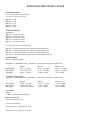
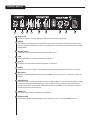
1
2
3
4
5
6
7
8
9
10
7
8
9
4
2
11
5
6
10
11
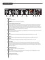
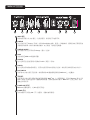
Front Panel MAX
®
158
1

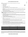
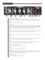
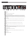
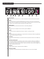
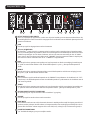
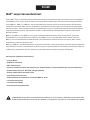
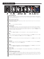
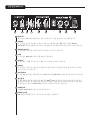
INPUT JACK
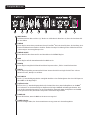
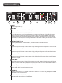
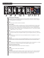
Plug your bass into this 1/4" jack. Connect your bass prior to turning on the power switch.
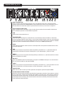
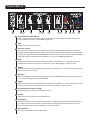
VINTAGE
This control introduces patented Peavey TransTube
®
circuitry, with an EQ curve that simulates the sound
of a vintage tube bass amp. Increase the amount of “tube like” distortion/compression by turning the
knob clockwise.
VINTAGE ON/OFF
This push button switch allows you to turn the Vintage control on and o.
GAIN
This control sets the overall volume level of the MAX 126.
HIGH EQ
This control allows you to dial in high frequencies or “treble” sounds for your bass.
LOW EQ
This control adds bottom end to your sound. Use this control for low sounds or to add more “oomph”
to your bass.
AUX/LINE IN
This standard 1/4" input jack allows you to connect a tape or CD player to your MAX 126 and play
along.
HEADPHONE JACK
This standard 1/4" input jack allows you to connect standard headphones to the MAX
®
126. Turn the
Vintage and Gain controls all the way down before using headphones. Slowly turn up the volume and nd
a comfortable listening level. When headphones are connected to the MAX 126‚ the speaker is automati-
cally turned o.
POWER LED
This LED illuminates when power is supplied to the MAX 126.
POWER SWITCH
This two-way rocker switch applies power to the unit when placed in the ON position.
1
2
3
4
5
6
7
8
9
10
7
8
9
4
2
5
6
Front Panel MAX
®
126
1
3

MAX
®
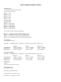
SERIES SPECIFICATIONS
POWER CONSUMPTION:
(1/8 rated power, 1KHz sine wave)
120vac/60Hz, 230vac/50Hz
MAX 126 = 26W
MAX 158 = 50W
MAX 110 = 33W
MAX 112 = 63W
MAX 115 = 78W
POWER AMPLIFIER:
(Rated Power)
MAX 126 = 10 Watts into 4 ohms
MAX 158 = 20 Watts into 4 ohms
MAX 110 = 100 Watts into 8 ohms
MAX 112 = 200 Watts into 8 ohms
MAX 115 = 300 Watts into 8 ohms
(1% THD, 1KHz sine wave, nominal line)
MAX 126 = 10 Watts continuous into 4-ohm internal speaker load
MAX 158 = 21 Watts continuous into 4-ohm internal speaker load
MAX 110 = 120 Watts continuous into 8-ohm internal speaker load
MAX 112/115 = 200 Watts continuous into 8-ohm internal speaker load
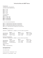
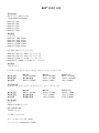
PRE-AMPLIFIER:
Maximum Input Sensitivity:
(PRE GAIN = 10, LOW/MID/HIGH = 5, VOLUME = 10, all voicing switches defeated)
Max 158 Max 110 Max 112 / 115
Passive Input 11mV / -36.95dBu 30mV / -28.24dBu 40mV / -25.74dBu
Active Input same as passive 90mV / -18.70dBu 110mV / -16.95dBu
Auxiliary Input 420mV / -5.32dBu 900mV / 1.3dBu 1.0V / 2.22dBu
Nominal Input Sensitivity:
(PRE GAIN = 5, LOW/MID/HIGH = 5, VOLUME = 5, all voicing switches defeated)
Max 158 Max 110 Max 112 / 115
Passive Input 290mV / -8.53dBu 400mV / -5.74dBu 500mV / -3.8dBu
Active Input same as passive 1.10V / 3.05dBu 1.40V / 5.14dBu
Auxiliary Input same as maximum 1.80V / 7.32dBu 2.10V / 8.66dBu
Headphone Output:
(Mono)
50mW x 2 into 8-ohm minimum load
Direct Interface (DI):
112/115 models only
Pre-EQ, unity buer
Output Signal Level = Input Level – 10dB
Noise Floor = 0.95mV(rms) = -78dBu
Page is loading ...
Page is loading ...
Page is loading ...
Page is loading ...

Panel Posteriorl
SALIDA DE AURICULARES
Salida de auricular de 1/8" para monitoreo personal.
AUX INPUT
Este conector de entrada de 1/8” le permite conectar el reproductor de CD o reproductor de MP3 al
amplificador de graves de su Serie MAX y tocar al mismo tiempo.
LUZ INDICADORA DEL INTERRUPTOR DE ENCENDIDO /DDT
™
Este interruptor de doble propósito se usa para encender y apagar el amplificador. Cuando el DDT
(Técnica de detección de distorsión) detecta la fijación de la amplificación de potencia, un circuito de
potencia se activa y los LED en el interruptor de potencia cambian a rojo.
PRECAUCIÓN: El interruptor de encendido/apagado en esta unidad no acciona en ambos lados de las
redes principales. Podría existir energía peligrosa en el chasis aún si el interruptor de apagado/encendi-
do está en la posición OFF (APAGADO).
ENTRADA DE POTENCIA CA:
Este es un receptáculo para un cable de línea IEC que brinda potencia CA a la unidad. Conecte el cable
de línea para este conector brinda potencia a la unidad. El equipo podría resultar dañado si el voltaje de
línea usado es inadecuado. (Consulte la marcación de la línea de voltaje en la unidad).
Nunca retire la conexión a tierra en ningún equipo. Se incluye para su seguridad. Si el enchufe usado no
cuenta con conexión a tierra, se debe usar un adaptador adecuado y el tercer cable se debe conectar a
tierra correctamente. Para prevenir el riesgo de descarga eléctrica, siempre asegúrese que el amplifica-
dor y todo el equipo asociado esté correctamente puesto a tierra.
NOTE: FOR UK ONLY
As the colors of the wires in the mains lead of this apparatus may not correspond with the colored
markings identifying the terminals in your plug, proceed as follows: (1) The wire that is colored green
and yellow must be connected to the terminal that is marked by the letter E, or by the Earth symbol, or
colored green or green and yellow. (2) The wire that is colored blue must be connected to the terminal
that is marked with the letter N, or the color black. (3) The wire that is colored brown must be connected
to the terminal that is marked with the letter L, or the color red.
12
13
14
14
15
15
11
Page is loading ...
Page is loading ...
Page is loading ...
Page is loading ...
Page is loading ...
Page is loading ...
Page is loading ...

Panneau arrière
SORTIE CASQUE
Sortie casque de 3 mm pour un suivi personnel.
AUX INPUT
Cette prise d'entrée de 3 mm sert à brancher un lecteur CD ou MP3 sur votre amplificateur de basses de
la série MAX
®
VOYANT LUMINEUX ALIM/DDT
™
Cet interrupteur à deux fonctions sert à mettre en marche et à arrêter l'amplificateur. Lorsque le DDT
(Distortion Detection Technique) détecte un écrêtage, un circuit de protection s'active et les DEL de
l'interrupteur s'allument en rouge.
ATTENTION : L'interrupteur marche/arrêt de cet appareil ne coupe pas l'alimentation primaire du ré-
seau. Le châssis peut contenir une énergie dangereuse, même quand l'interrupteur marche/arrêt est sur
OFF.
PRISE ENTRÉE D'ALIMENTATION CA :
C'est la prise prévue pour un cordon d'alimentation CEI qui fournit l'alimentation CA à l'appareil. Bran-
chez ici le cordon d'alimentation pour alimenter l'appareil. L'équipement peut s'endommager si une
tension de ligne incorrecte est appliquée. (Voir la marque de tension de ligne de l'appareil).
Veillez à ne jamais rompre la broche de terre sur l’équipement. Ce dispositif est prévu à titre de sécurité.
Si la prise de courant est dépourvue de broche de terre, un adaptateur de mise à la terre approprié doit
être utilisé et le troisième fil doit être mis à la terre convenablement. Pour éviter tout risque de choc
électrique ou d'incendie, s'assurer toujours que l'amplificateur et tous les équipements associés soient
correctement mis à la terre.
NOTE : FOR UK ONLY
As the colors of the wires in the mains lead of this apparatus may not correspond with the colored
markings identifying the terminals in your plug, proceed as follows : (1) The wire that is colored green
and yellow must be connected to the terminal that is marked by the letter E, or by the Earth symbol, or
colored green or green and yellow. (2) The wire that is colored blue must be connected to the terminal
that is marked with the letter N, or the color black. (3) The wire that is colored brown must be connected
to the terminal that is marked with the letter L, or the color red.
12
13
14
14
15
15
11
Page is loading ...
Page is loading ...
Page is loading ...
Page is loading ...
Page is loading ...
Page is loading ...
Page is loading ...
Page is loading ...
Page is loading ...
Page is loading ...
Page is loading ...
Page is loading ...
Page is loading ...
Page is loading ...
Page is loading ...
Page is loading ...
Page is loading ...
Page is loading ...
Page is loading ...
Page is loading ...
Page is loading ...
Page is loading ...
Page is loading ...

Achterpaneel
AUX INPUT
Deze 1/8" ingangsaansluiting stelt u in staat om een CD-speler of MP3-speler op uw MAX
®
Serie basver-
sterker aan te sluiten en af te spelen.
AAN-/UITSCHAKELAAR/DDT™ INDICATIE-LED
Deze dubbele functieschakelaar wordt gebruikt om de versterker aan of uit te schakelen. Wanneer de
DDT (vervormingsdetectietechniek) het clippen van de eindversterker detecteert, wordt een bescher-
mingscircuit in werking gesteld en de LED's in de aan-/uitschakelaar veranderen naar rood.
LET OP: De aan-/uitschakelaar van dit apparaat onderbreekt niet beide contacten van het lichtnet.
Gevaarlijke spanning kan binnenin het chassis aanwezig zijn ondanks dat de aan-/uitschakelaar op de
"UIT"-stand staat.
VOEDINGSAANSLUITING:
Dit is de connector voor een IEC-netsnoer waarmee netspanning aan de eenheid wordt geleverd. Sluit
het netsnoer aan op deze connector om de eenheid te voeden. Het gebruik van een onjuiste netspan-
ning kan tot schade aan de apparatuur leiden. (Zie de netspanningaanduiding op de eenheid).
Breek nooit de aardingspen af. Het dient voor uw veiligheid. Als het gebruikte stopcontact geen aar-
dingscontact heeft, moet een geschikte geaard stopcontact worden gebruikt, en de derde draad moet
goed worden geaard. Als u het risico van schokken of brandgevaar wilt voorkomen, zorg ervoor dat de
versterker en alle bijbehorende apparatuur goed geaard zijn.
NOTE: FOR UK ONLY
As the colors of the wires in the mains lead of this apparatus may not correspond with the colored
markings identifying the terminals in your plug, proceed as follows: (1) The wire that is colored green
and yellow must be connected to the terminal that is marked by the letter E, or by the Earth symbol, or
colored green or green and yellow. (2) The wire that is colored blue must be connected to the terminal
that is marked with the letter N, or the color black. (3) The wire that is colored brown must be connected
to the terminal that is marked with the letter L, or the color red.
12
13
14
14
15
15
Page is loading ...
Page is loading ...
Page is loading ...
Page is loading ...
Page is loading ...
Page is loading ...
Page is loading ...
Page is loading ...
Page is loading ...
Page is loading ...
Page is loading ...
Page is loading ...
Page is loading ...

Takapaneeli
OLEELLISIN ASIA: efektiä käyttämällä saat matalimmat mahdolliset äänet kuulostamaan uskomattoman
kovilta ja kirkkailta. Harjoittelu kuulokkeilla ei ole enää kompromissi. Se toimii jopa soinnuille!
VIHJE: Saat parhaat tulokset kun käytät efektiä nostamatta BASS-säädintä äärimmilleen. Näin efekti
kuuluu paremmin.
VOLUME
Tämä säädin ohjaa vahvistimen äänenvoimakkuutta.
TUNE/MUTE
Painikkeen painaminen kytkee kromaattisen virittimen ja mykistää kaiuttimen lähdön. LED-näyttö ilmai-
see soitetun nuotin, kun taas vihreät ja punaiset LED-valot näytön yläpuolella ilmaisevat onko nuotti
alavireessä (punainen), ylävireessä (punainen) vai vireessä (vihreä). Kytkin mykistää myös DI:n.
AUX INPUT
Tämän 1/8 tuuman tuloliittimen kautta voit kytkeä MAX-sarjan bassovahvistimeen CD- tai MP3-soitti-
men ja soittaa sen mukana
KUULOKELÄHTÖ
1/8 tuuman kuulokelähtö omaan monitorointiin.
VIRTAKYTKIN/DDT™-MERKKIVALO
Tällä kaksitoimisella kytkimellä voidaan kytkeä vahvistin päälle ja pois. Kun DDT (säröntunnistus) ha-
vaitsee päätevahvistimen leikkaavan, kytketään suojauspiiri päälle ja virtakytkimen LED-valot syttyvät
punaisiksi.
VAARA: Laitteen virtakytkin ei katkaise ensiövirran molempia puolia. Laitteen sisällä voi olla vaarallinen
jännite myös, kun virtakytkin on POIS-asennossa.
VERKKOVIRTATULO:
Tämä liitin on IEC-virtajohdolle, joka syöttää laitteeseen AC-virtaa.
Kytke laitteen virta kytkemällä virtajohto tähän liittimeen. Väärän
verkkojännitteen käytöstä voi seurata laitteen vaurioituminen. (Katso
laitteessa olevaa verkkojännitteen merkintää).
Älä katkaise laitteen maadoitusnastaa. Se on tarkoitettu suojaamaan
sinua. Laitteen saa liittää vain maadoitettuun pistorasiaan. Sähköisku-
ja tulipalovaaran välttämiseksi tulee aina varmistaa, että vahvistin ja
siihen kytketyt laitteet on maadoitettu.
NOTE: FOR UK ONLY
As the colors of the wires in the mains lead of this apparatus may not
correspond with the colored markings identifying the terminals in your plug, proceed as follows: (1) The
wire that is colored green and yellow must be connected to the terminal that is marked by the letter E,
or by the Earth symbol, or colored green or green and yellow. (2) The wire that is colored blue must be
connected to the terminal that is marked with the letter N, or the color black. (3) The wire that is colored
brown must be connected to the terminal that is marked with the letter L, or the color red.
12
13
14
17
17
18
15
16
18
Page is loading ...

Takapaneeli
AUX INPUT
Tämän 1/8 tuuman tuloliittimen kautta voit kytkeä MAX
®
-sarjan bassovahvistimeen CD- tai MP3-soitti-
men ja soittaa sen mukana.
VIRTAKYTKIN/DDT™-MERKKIVALO
Tällä kaksitoimisella kytkimellä voidaan kytkeä vahvistin päälle ja pois. Kun DDT (säröntunnistus) ha-
vaitsee päätevahvistimen leikkaavan, kytketään suojauspiiri päälle ja virtakytkimen LED-valot syttyvät
punaisiksi.
VAARA: Laitteen virtakytkin ei katkaise ensiövirran molempia puolia. Laitteen sisällä voi olla vaarallinen
jännite myös, kun virtakytkin on POIS-asennossa.
VERKKOVIRTATULO:
Tämä liitin on IEC-virtajohdolle, joka syöttää laitteeseen AC-virtaa. Kytke laitteen virta kytkemällä vir-
tajohto tähän liittimeen. Väärän verkkojännitteen käytöstä voi seurata laitteen vaurioituminen. (Katso
laitteessa olevaa verkkojännitteen merkintää).
Älä katkaise laitteen maadoitusnastaa. Se on tarkoitettu suojaamaan sinua. Laitteen saa liittää vain
maadoitettuun pistorasiaan. Sähköisku- ja tulipalovaaran välttämiseksi tulee aina varmistaa, että vah-
vistin ja siihen kytketyt laitteet on maadoitettu.
NOTE: FOR UK ONLY
As the colors of the wires in the mains lead of this apparatus may not correspond with the colored
markings identifying the terminals in your plug, proceed as follows: (1) The wire that is colored green
and yellow must be connected to the terminal that is marked by the letter E, or by the Earth symbol, or
colored green or green and yellow. (2) The wire that is colored blue must be connected to the terminal
that is marked with the letter N, or the color black. (3) The wire that is colored brown must be connected
to the terminal that is marked with the letter L, or the color red.
12
13
14
14
15
15
Page is loading ...
Page is loading ...
Page is loading ...
Page is loading ...
Page is loading ...
Page is loading ...
Page is loading ...

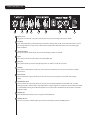
Painel traseiro
SAÍDA DE FONE DE OUVIDO
Saída de fone de ouvido de 1/8" para monitoramento pessoal.
AUX INPUT
Esse conector de entrada de 1/8" permite que você conecte um tocador de CD ou de MP3 à sua série
MAX
®
de amplificador para contrabaixo.
CHAVE DE ENERGIA/LUZ INDICADORA DDTTM
Esta chave de dupla função é usada para ligar e desligar o amplificador. Quando o DDT (Técnica de
Detecção de Distorção) sente que o amplificador de potência está cortando, um circuito de proteção é
ativado e os LEDs na chave de energia mudam para vermelho.
CUIDADO: A chave on/off nessa unidade não corta ambos os lados da energia primária. Energia perigo-
sa pode estar presente dentro do chassi mesmo quando a chave on/off estiver na posição OFF.
ENTRADA DE ENERGIA AC:
Este é o terminal para um cabo de energia IEC que fornece energia AC à unidade. Conecte o cabo de
energia a esse conector para fornecer energia à unidade. O equipamento pode ser danificado se for
usada uma tensão de alimentação imprópria. (Consulte o valor de tensão marcado na unidade).
Nunca quebre o pino de aterramento de nenhum equipamento. Ele é fornecido para sua segurança. Se
a tomada utilizada não tiver um pino de aterramento, um adaptador de aterramento adequado deve ser
usado e o terceiro fio deve ser aterrado adequadamente. Para prevenir o risco de choque ou incêndio,
sempre certifique-se de que o amplificador e todos os equipamentos associados estejam corretamente
aterrados.
NOTE: FOR UK ONLY
As the colors of the wires in the mains lead of this apparatus may not correspond with the colored
markings identifying the terminals in your plug, proceed as follows: (1) The wire that is colored green
and yellow must be connected to the terminal that is marked by the letter E, or by the Earth symbol, or
colored green or green and yellow. (2) The wire that is colored blue must be connected to the terminal
that is marked with the letter N, or the color black. (3) The wire that is colored brown must be connected
to the terminal that is marked with the letter L, or the color red.
12
13
14
14
15
15
11
Page is loading ...
Page is loading ...
Page is loading ...
Page is loading ...
Page is loading ...

后面板
最主要的是:使用这个效果会令您所能演奏出的最低音调听起来令人难以置信的响亮和清澈。戴耳
机练习不再是一种不得已的折衷方案,它甚至可以与和弦一起使用!
提示:要达到最佳效果,在使用这个效果时尽量不要将BASS(低音)控制提升到极端设置,这样会
使效果更加的明显。
VOLUME
此旋钮控制放大器的总体音量。
TUNE/MUTE
按下这个按钮将打开半音阶调谐器,同时静音进入扬声器的输出。LED 显示屏显示正在演奏的音调,
而显示屏上方的红色和绿色 LED 指示灯则显示音调是降调(红色)、升调(红色)、还是合调(绿
色)。这个开关还静音 DI(直接接口)。
AUX INPUT
这个 1/8" 输入插孔让您能将一台 CD 播放器或 MP3 播放器连接到 MAX 系列低音放大器一齐播放。
耳机输出
1/8" 耳机输出,供个人监听用。
电源开关/DDT
™
指示灯
这一两用开关用于打开和关闭放大器。当 DDT(失真监测技术)感应到功放削波时,保护电路打
开,电源开关上的 LED 指示灯转为红色。
小心:此设备的 ON/OFF 开关并不将两边的主电源都切断, 即使 ON/OFF 开关在 OFF 的位置,机箱
内仍可能存在有害电能。
交流电源输入:
这是 IEC(国际电工委员会)电源线插座,向设备提供交流电源。将
电源线连接到此插座,向设备提供电源。如果使用不当电压,可能
导致设备损坏。(参见设备上标明的电源电压)。
千万不要折断任何设备上的接地脚。这是为了您的安全起见。如果
使用的电源插座没有接地脚,则应使用相应的接地转换器,并将第
三根导线正确接地。为防止触电或火灾危险,一定要确认放大器及
其所有附加设备都正确接地。
NOTE: FOR UK ONLY
As the colors of the wires in the mains lead of this apparatus may not
correspond with the colored markings identifying the terminals in your
plug, proceed as follows: (1) The wire that is colored green and yellow must be connected to the termi-
nal that is marked by the letter E, or by the Earth symbol, or colored green or green and yellow. (2) The
wire that is colored blue must be connected to the terminal that is marked with the letter N, or the color
black. (3) The wire that is colored brown must be connected to the terminal that is marked with the let-
ter L, or the color red.
12
13
14
17
17
18
15
16
18
Page is loading ...
Page is loading ...
Page is loading ...
Page is loading ...
Page is loading ...
Page is loading ...
Page is loading ...
Page is loading ...
Page is loading ...
Page is loading ...
Page is loading ...
Page is loading ...
Page is loading ...
Page is loading ...
Page is loading ...
Page is loading ...
Page is loading ...
Page is loading ...
Page is loading ...
Page is loading ...
Page is loading ...
Page is loading ...
Page is loading ...
Page is loading ...
Page is loading ...
-
 1
1
-
 2
2
-
 3
3
-
 4
4
-
 5
5
-
 6
6
-
 7
7
-
 8
8
-
 9
9
-
 10
10
-
 11
11
-
 12
12
-
 13
13
-
 14
14
-
 15
15
-
 16
16
-
 17
17
-
 18
18
-
 19
19
-
 20
20
-
 21
21
-
 22
22
-
 23
23
-
 24
24
-
 25
25
-
 26
26
-
 27
27
-
 28
28
-
 29
29
-
 30
30
-
 31
31
-
 32
32
-
 33
33
-
 34
34
-
 35
35
-
 36
36
-
 37
37
-
 38
38
-
 39
39
-
 40
40
-
 41
41
-
 42
42
-
 43
43
-
 44
44
-
 45
45
-
 46
46
-
 47
47
-
 48
48
-
 49
49
-
 50
50
-
 51
51
-
 52
52
-
 53
53
-
 54
54
-
 55
55
-
 56
56
-
 57
57
-
 58
58
-
 59
59
-
 60
60
-
 61
61
-
 62
62
-
 63
63
-
 64
64
-
 65
65
-
 66
66
-
 67
67
-
 68
68
-
 69
69
-
 70
70
-
 71
71
-
 72
72
-
 73
73
-
 74
74
-
 75
75
-
 76
76
-
 77
77
-
 78
78
-
 79
79
-
 80
80
-
 81
81
-
 82
82
-
 83
83
-
 84
84
-
 85
85
-
 86
86
-
 87
87
-
 88
88
-
 89
89
-
 90
90
-
 91
91
-
 92
92
-
 93
93
-
 94
94
-
 95
95
-
 96
96
-
 97
97
-
 98
98
-
 99
99
-
 100
100
-
 101
101
-
 102
102
-
 103
103
-
 104
104
-
 105
105
-
 106
106
-
 107
107
-
 108
108
-
 109
109
-
 110
110
-
 111
111
-
 112
112
-
 113
113
-
 114
114
-
 115
115
-
 116
116
-
 117
117
-
 118
118
-
 119
119
-
 120
120


Peavey MAX 126 10-Watt Bass Amp Combo Owner's manual
- Category
- Musical Instrument Amplifier
- Type
- Owner's manual
Ask a question and I''ll find the answer in the document
Finding information in a document is now easier with AI
in other languages
- italiano: Peavey MAX 126 10-Watt Bass Amp Combo Manuale del proprietario
- français: Peavey MAX 126 10-Watt Bass Amp Combo Le manuel du propriétaire
- español: Peavey MAX 126 10-Watt Bass Amp Combo El manual del propietario
- Deutsch: Peavey MAX 126 10-Watt Bass Amp Combo Bedienungsanleitung
- Nederlands: Peavey MAX 126 10-Watt Bass Amp Combo de handleiding
- português: Peavey MAX 126 10-Watt Bass Amp Combo Manual do proprietário
- 日本語: Peavey MAX 126 10-Watt Bass Amp Combo 取扱説明書
- svenska: Peavey MAX 126 10-Watt Bass Amp Combo Bruksanvisning
- suomi: Peavey MAX 126 10-Watt Bass Amp Combo Omistajan opas
Related papers
-
Peavey XR8300 Owner's manual
-
-
Peavey 3588440 User manual
-
-
 Peavy 4000 User manual
-
Peavy IPR2 2000 Power Amplifier User manual
-
-
-
Peavy KB5 Owner's manual
-
Peavey MX16a Owner's manual

Other documents
-
Crest Audio CC 4000 User manual
-
Crest Audio Pro-LITE 2.0 DSP User manual
-
Crest Audio CLh 6000C User manual
-
-
-
-
-
-
-