PROEL AUP120 User manual
- Category
- Audio amplifiers
- Type
- User manual
This manual is also suitable for

MANUALE UTENTE / INSTRUCTION MANUAL
AUP120/240/480R
Amplificatore di potenza
Power Amplifier Unit
Page is loading ...
Page is loading ...
Page is loading ...
Page is loading ...
Page is loading ...
Page is loading ...
Page is loading ...
Page is loading ...
Page is loading ...
Page is loading ...
Page is loading ...
Page is loading ...
Page is loading ...

Caratteristiche Tecniche
Il prodotto è conforme alla Direttiva 89/336/CEE (Compatibilità Elettromagnetica)
e successive modifiche 92/31/CEE e 93/68/CEE, secondo i seguenti standard:
EN 50082-1:1997, EN 55013:1990, EN 55020:1994
inoltre, è conforme alla Direttiva 73/23/CEE (Bassa Tensione)
e successive modifiche 93/68/CEE, secondo il seguente standard:
EN 60065:1998
MODEL AUP120R AUP240R AUP480R
Output Power RMS 120/180MAX 240/360MAX 480/680MAX
INPUTS
Line input
100mV-500mV-
1V/47Kohm select.
100mV-500mV-
1V/47Kohm select.
100mV-500mV-
1V/47Kohm select.
Telephone/Emergency
Variable gain -
600ohms
Variable gain -
600ohms
Variable gain -
600ohms
Microphone for Paging Variable gain - with
priority contact
Variable gain - with
priority contact
Variable gain - with
priority contact
Frequency range (+/-
3dB)
50 -20KHz 50 -20KHz 50 -20KHz
Tone Control Low/High Low/High Low/High
OUTPUTS
Speakers (Music and
speech)
100/70/50V - 8 ohms 100/70/50V - 8 ohms 100/70/50V - 8 ohms
Speakers (only speech) 100V 100V 100V
Wall attenuators 24Vdc for bypass 24Vdc for bypass 24Vdc for bypass
Line output 1 V/600ohm 1 V/600ohm 1 V/600ohm
THD distortion < 1% @ (Pnom. 1Kz) < 1% @ (Pnom. 1Kz) < 1% @ (Pnom. 1Kz)
S/N Ratio > 80 dB > 80 dB > 80 dB
Power Supply 230/117Vac-50/60Hz
24Vdc for Emergency
230/117Vac-50/60Hz
24Vdc for Emergency
230/117Vac-50/60Hz
24Vdc for Emergency
Ambient temperature 0 - 40 °C 0 - 40 °C 0 - 40 °C
19” RACK Dimensions
(WxHxD)
483 x 88 x 300 mm 483 x 88 x 300 mm 483 x 133 x 300 mm
Weight 10 Kg 13 Kg 25 Kg
INPUT/OUTPUT
CONNECTORS
Line IN/Line out 2 x XLR and 1 RCA
L/R each
2 x XLR and 1 RCA L/R
each
2 x XLR and 1 RCA
L/R each
Others in/out screw terminal screw terminal screw terminal
La Proel SpA persegue una politica di costante ricerca e sviluppo, di conseguenza si riserva il diritto di
apportare miglioramenti ai prodotti esistenti, senza preavviso e in qualunque momento.

1. IMPORTANT SAFETY INSTRUCTIONS
CAUTION: To reduce the risk of electric shock do not remove cover (or back panel). No
user serviceable parts inside. Refer servicing to qualified personnel only.
WARNING: To reduce the risk of fire or electric shock, do not expose this apparatus to
rain or moisture.
This symbol is intended to alert the user of the presence of uninsulated
dangerous voltage within the product enclosure that may be of sufficient
magnitude to constitute a risk of electric shock to persons.
This symbol is intended to alert the user of the presence of important operating
and maintenance (servicing) instruction in the literature accompanying the
appliance. Please carefully read the owner’s manual.
INSTRUCTIONS:
All safety and operating instructions should be read before the product is operated.
Retain these instructions:
All safety and operating instructions should be retained for future reference.
This owner’s manual should be considered as a part of the product and it must accompany it
every time, and delivered to the new user when this product is sold. In this way the new owner will
be aware of all the installations, operating and safety instructions.
Heed all warnings:
All warnings on the product and in owner’s manual should be adhered to.
Heed all warnings.
Follow all instructions:
All operating and user’s instructions must be followed.

Sentences preceded by
symbol contain important safety instruction. Please read it carefully.
DETAILED SAFETY INSTRUCTIONS.
Water and moisture:
This apparatus should not be used near water (i.e. bathtub, kitchen sink, swimming pools,
etc.)
Ventilation:
This apparatus should be placed in a position that doesn’t interfere with correct ventilation.
This unit, for example, should not be placed on a bed, sofa cover o similar surfaces that could
cover ventilation openings, or placed in a built-in installation, such a bookcase or a cabinet
that could block air flow trough ventilation openings.
Heat:
This apparatus should be placed away from heat sources, like radiators, heat registers, stoves
or other products (including amplifiers) that produce heat.
Power sources:
• This apparatus should be connected only to power source type specified in this owner’s
manual or on the unit.
• If the supplied AC power cable plug is different from the wall socket, please contact an
electrician to change the AC power plug.
Grounding or Polarization:
• All precautions must be observed to don’t defeat grounding or polarization.
• Unit metal parts are grounded through the AC power cord.
• If the AC power outlet doesn’t have grounding, consult an electrician for outlet grounding.
Power cord protection:
The power cord should be routed in a way it will not be walked on or pinched by items placed
upon or against it, paying particular attention to cords at plugs, convenience receptacles and
wall outlet.
Cleaning:
• You can clean the unit with a compressed air flow or a wet cloth.
• Don’t clean the unit using solvents like trichloroethylene, thinners, alcohol, or other fluids
with very strong volatility and flammability.
Non use periods:
The unit AC power cord should be unplugged from the outlet if it’s unused for a long period.

Objects or liquid entry inside the unit:
Be careful that no objects fall or liquid is spilled inside the unit through ventilation openings.
Safe power line use:
• Keep firmly the plug and the wall outlet while disconnecting the unit from AC power.
• If the unit will not be used for a long period of time, please unplug the power cord from AC
power outlet.
• To avoid unit power cord damages, please don’t strain the AC power cable and don’t
bundle it.
• In order to avoid unit power cord damages, please be sure that the power cord is not
walked on or pinched by heavy objects.
Unit relocation:
Before any unit relocation please control the unit is turned off. The power cord must be
unplugged by the wall outlet, and all the connections wires should be disconnected as well.
Don’t open this unit:
Don’t attempt to open or to repair this unit by yourself. For any problem solution not described
in this owner’s manual, please refer to qualified personnel only or consult us or your National
Distributor. Any improper operation could result in fire or electric shock.
Damages requiring services:
• Don’t attempt to do operations not described in this user’s manual.
• In the following cases please refer to an authorized maintenance center or skilled
personnel:
- When the unit works improperly or it doesn’t work at all.
- If power cord or plug are damaged.
- If liquid has spilled, or objects have fallen into the unit.
- The unit has been exposed to rain.
- The unit doesn’t operate normally o it exhibits a marked change in performance.
- If the product has dropped or it has been damaged in any way.
Maintenance:
The user shouldn’t attempt maintenance operation not described in this user’s manual. Every
maintenance operation should be done by qualified personnel only.
IMPORTANT SAFETY INSTRUCTIONS:
• Install this unit following owner’s manual instructions.
• Don’t install, connect or disconnect power supply when the unit is powered, otherwise
there’s an high risk of electric shock.
• Don’t open the unit, there are no user serviceable parts inside.
• If you detect a particular smell from the unit, please immediately turn it off and disconnect
the AC power cord.
• Don’t block the unit ventilation openings.
• Avoid using this unit in overload for a long period.
• Don’t force commands (switches, controls, etc.)

• To obtain good speakers wire contacts, please tighten the screw terminals firmly.
•
For safety reason, don’t defeat the grounding connection. Grounding is useful for user
safety.
• Use only connectors and accessories suggested by the manufacturer. .
• This unit should be placed in a rack (see INSTALLATION) and kept far from:
Wet places
Direct exposure to heat sources (like sun light)
Non properly ventilated places
• Disconnect the power cord during storms or when the unit is not used.
• In order to prevent fire and electric shock risks, it’s necessary to keep the unit far
from sprinkling and drops. Please don’t put cups, vases or other object containing liquids
over the unit. In case of interferences from source signal, THD value will raise over 10%.
Don’t place this unit in a bookshelf o in other places with small room.
• PROEL S.P.A. is not responsible for any damage that occurs due to a wrong unit
installation.

Thank you for choosing one of Proel products, and for your confidence towards
our brand, synonymous of professionalism, accuracy, high quality and reliability.
All our products are CE approved and designed for continuous use in
professional installation systems.
14. Description
The power units series AUP120/240/480R have been designed specifically
for microphone announcement and music diffusion in all PA installation
applications . The main features are as follows:
• One input/output balanced with XLR connector.
• One input/output unbalanced with RCA connector
• 4 Outputs : one output at constant impedance (8Ω) and three
outputs at constant voltage (25 – 70 – 100 V).
• A further output 100V available only for call and announcement
from microphone stand or telephone.
• Level indicator and overload led indicator.
• Input for one or more pre-amplified microphone stand BM100A
with priority function.
• One input for call from telephone central with VOX priority .
• Low & high tone control and general master.
• PA-HF Filter to be rear inserted.
• GROUND-LIFT rear selector.
• 24Vdc output with volume attenuator bypass during the
announcements .
• Main power selector (117 – 230 V ca).
• 24 Vdc for emergency power supply.
15. FUNCTIONS AND CONTROL
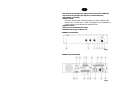
(1) Volume control
Such knob is used for output volume control.
(2) Led level indicator - Vu meter.
Gives an indication on signal level. For a correct amplifier use, the
volume level must be set between –20 dB e 0 dB indicated by ON
status of the first 5 LEDS , When the volume level makes only the
latest 2 LEDS ON status (+3 dB +6 dB), the output signal could be
distorted and the volume must be reduced

(3) Overload Led
This LED is on when the self-protection process is active .
(4) Main power switch
(5) Tone control
Tone control operates for high and low frequency range between
+/- 10 dB in order to allow the correct reproduced signal equalization
(6) Protection Fuse
Prevent the unit against main power fluctuation and can be replaced .
(7) Terminal screw for emergency power supply
These 2 Terminal screws must be connected to 24VDC emergency
supply to allow the operating continuity in case of black -out.
(8) Power supply Selector 230/117Vca 50/60Hz.
(9) 24Vdc bypass control.
Such control is available contemporaneously to a voice
announcement sent from BM100A or from telephonce central .
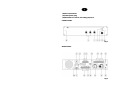
(10) Terminal screws for principal speakers output line
These 5 terminal screws are used to connect diffusers of 8Ω 50 V, 70
V e 100 V ( for music and announcement signal presence).
(11) Terminal screws for secondary speakers line
Such terminal can be used to connect speakers line to 100V (signal
present only for microphone stand call or central telephone call).
(12) Balanced and unbalanced input connectors
For peripheral sources of audio signal to be amplified (pre amplifier,
mixer, or an another amplifier etc.). This input is valid only for signal of
high level.
(13) Balanced and unbalanced output connectors
For connection of amplifiers or power amplifiers in cascade.
(14) Terminal screws for BM100A microphone stand connections.
This microphone stand must be connected as per the following
scheme description. Input is only for signal of high level.
(15) Terminal screws for telephone central connections.
To this input must be connected to a high level audio signal received
from the telephone central . Input to be used only for high level signal
balanced or unbalanced
(16) Gain control for BM100A microphone stand.
(17) Gain control for telephonce central.
(18) Ground-lift Selector
(19) PA-HF Filter.
Allows the PA-HF insertion with break at 400Hz -3dB.
Such filter is necessary when it is necessary to pilot only horn
speakers or diffuse voice signal .

(20) Ground terminal
(21) Main power plug
(22) Brackets for rack 19” mounting purposes.
FRONT PANEL
fig.1
REAR PANEL
fig.2

16. INSTALLATION
Note
• To allow normal cooling of terminal parts, ensure to install the
amplifier in a habitat correctly ventilated far away from heat
sources and avoid direct exposition to sun rays.
• Do not install the unit in ambient with vibration risks .
• When the power amplifier is installed in a rack, ensure that this
rack is complying with EN 60439-1 standards and that the
ventilation of rear rack panel is perfect .
.
The unit is supplied with rubber feet to ensure a good plan stability .
17. CONNECTIONS
Attention
• For connections revert to authorized installer to avoid to damage
the unit .
• Plug to the main AC power before ON status selection and unplug
after OFF status selection
To connect the unit to the main power insert in position 21 fig.2, the cable
supplied in the power unit package.
18. DC POWER SUPPLY
Attentino
• Advice: do not use contemporaneously the main power supply
(230Vac) and (24 Vdc) power emergency supply to ensure the
good apparatus operating
• To access to 24Vdc Terminal connections (fig.2) unscrew to
remove the cover.
In order to supply in the right way and avoid to overheat , use only
cable with at least a section of 2,5 mm
2
.

Nota
In case 24Vdc power supply is supplied by batteries , please be
kindly informed that the apparatus has not been set to provide to the
batteries recharge .
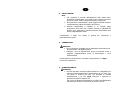
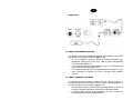
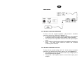
19. BALANCED/UNBALANCED INPUT CONNECTIONS
For Balanced and unbalanced connections, make reference to the
following schemes.
Attention
To prevent
electric shock risks, do never touch the outputs when the unit is working
.
To access to the speakers terminal screws (fig.2 rif. 10) unscrew to
remove the cover.
20. BM100A STAND MICROPHONE CONNECTIONS
Connect BM100A terminal to terminal screws 14 of fig.2 as follows:

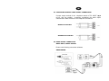
21. TELEPHONE CENTRAL AUDIO SIGNAL CONNECTIONS
Connect output terminal of the telephone central to TEL INPUT (fig.2
ref.15). Use the suitable connection considering the audio output
characteristics. Make reference to the telephone user manual.
Balanced connection
Unbalanced connection
22. AUDIO SIGNAL CONNECTION
MUSIC INPUT / MUSIC OUTPUT
Revert to the following conncection schemes.
UNBALANCED

UNBALANCED
23. LINE WITH CONSTANT IMPEDANCE
To have a line with constant impedante (8Ω) connect 2 terminales
respectively to terminal COM and 8Ω (fig.2 ref. 10).
• To ensure the maximum output, the total impedance of the speakers
connected to the line must be equal the amplifier output impedance.
• The total power of the speakers cannot be below the output amplifier
power .
• Advice: reduce to the minimum and as far as possible the connections
length . The cable section should be defined and increased
considering these distances.
24. LINE WITH CONSTANT VOLTAGE
To have a line at constant voltage (50 / 70 / 100 V) connect 2 terminals
respectively to COM and to the tension value of your choice (fig.2 ref10).
• The speakers must be with transformer with a input voltage equal to
the one supplied by the amplifier .
• Total power of the amplifier should not exceed the output power
amplifier.

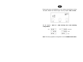
25. UNIT POWER AMPLIFIER SETTING
The power amplifier operating ode are as follows:
• STAND ALONE: The unit power amplifier operates in an
independent way
• MASTER: The power unit amplifier throughout i VOLUME, TREBLE,
and BASS control can control its output power and the MUSIC
OUTPUT signal. Such configuration allows the amplifier to control
other amplifiers set as SLAVE.
• SLAVE: the volume control circuit of the amplifier is by-passed . the
amplifier is piloted by Master power amplifier

Remove the cover and individuate on the volume potentiometers circuits
VOLUME, TREBLE and BASS copper side, the jumpers SW1 and SW2.
Set the jumpers SW1 and SW2 choosing one of the following
configurations :
Nota: The factory apparatus configuration is set at STAND ALONE status.

Technical Characteristics
The product is in compliance with Directive 89/336/EEC (Electromagnetic Compatibility)
and following modifications 92/31/EEC and 93/68/EEC, as the following standards:
EN 50082-1:1997, EN 55013:1990, EN 55020:1994
it is also in compliance with Directive 73/23/EEC (Low Voltage)
and following modifications 93/68/EEC, as the following standard:
EN 60065:1998
MODEL AUP120R AUP240R AUP480R
Output Power RMS 120/180MAX 240/360MAX 480/680MAX
INPUTS
Line input
100mV-500mV-
1V/47Kohm select.
100mV-500mV-
1V/47Kohm select.
100mV-500mV-
1V/47Kohm select.
Telephone/Emergency
Variable gain -
600ohms
Variable gain -
600ohms
Variable gain -
600ohms
Microphone for Paging Variable gain - with
priority contact
Variable gain - with
priority contact
Variable gain - with
priority contact
Frequency range (+/-
3dB)
50 -20KHz 50 -20KHz 50 -20KHz
Tone Control Low/High Low/High Low/High
OUTPUTS
Speakers (Music and
speech)
100/70/50V - 8 ohms 100/70/50V - 8 ohms 100/70/50V - 8 ohms
Speakers (only speech) 100V 100V 100V
Wall attenuators 24Vdc for bypass 24Vdc for bypass 24Vdc for bypass
Line output 1 V/600ohm 1 V/600ohm 1 V/600ohm
THD distortion < 1% @ (Pnom. 1Kz) < 1% @ (Pnom. 1Kz) < 1% @ (Pnom. 1Kz)
S/N Ratio > 80 dB > 80 dB > 80 dB
Power Supply 230/117Vac-50/60Hz
24Vdc for Emergency
230/117Vac-50/60Hz
24Vdc for Emergency
230/117Vac-50/60Hz
24Vdc for Emergency
Ambient temperature 0 - 40 °C 0 - 40 °C 0 - 40 °C
19” RACK Dimensions
(WxHxD)
483 x 88 x 300 mm 483 x 88 x 300 mm 483 x 133 x 300 mm
Weight 10 Kg 13 Kg 25 Kg
INPUT/OUTPUT
CONNECTORS
Line IN/Line out 2 x XLR and 1 RCA
L/R each
2 x XLR and 1 RCA L/R
each
2 x XLR and 1 RCA
L/R each
Others in/out screw terminal screw terminal screw terminal
Proel SpA pursue a policy of continuous research and development. Proel SpA reserve the right to modify
p
roduct circuitry and appearance at any moment, without prior notice.

PROEL S.p.A
(World Headquarters - Factory)
Via alla Ruenia 37/43
64027 Sant’Omero (Te) – Italy
Tel: +39 0861 81241
Fax: +39 0861 887862
E-mail: [email protected]
installation.proelgroup.com
-
 1
1
-
 2
2
-
 3
3
-
 4
4
-
 5
5
-
 6
6
-
 7
7
-
 8
8
-
 9
9
-
 10
10
-
 11
11
-
 12
12
-
 13
13
-
 14
14
-
 15
15
-
 16
16
-
 17
17
-
 18
18
-
 19
19
-
 20
20
-
 21
21
-
 22
22
-
 23
23
-
 24
24
-
 25
25
-
 26
26
-
 27
27
-
 28
28
-
 29
29
-
 30
30


PROEL AUP120 User manual
- Category
- Audio amplifiers
- Type
- User manual
- This manual is also suitable for
Ask a question and I''ll find the answer in the document
Finding information in a document is now easier with AI
in other languages
- italiano: PROEL AUP120 Manuale utente
Related papers
Other documents
-
Comelit 49AMP240 Technical Manual
-
 PROEL SOUND FREEONEX User manual
-
 Pro Audio AM626 User manual
-
Philips SPA4350/10 User manual
-
Audio Analogue Maestro Owner's manual
-
Paso DLC9000 Owner's manual
-
 MVOX electronics MV900 Datasheet
-
RCF EVOX 8 V2 Owner's manual
-
RCF EVox 12 Active Portable Line Array PA System User manual
-


