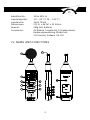
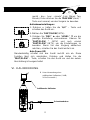
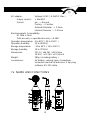
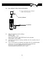
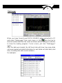
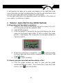
The TFA 31.2000 is a data logger sound level meter designed to measure and record sound levels in various environments for up to 50 hours of operation. It features a digital display for easy reading and allows users to select between A and C frequency weighting as well as fast and slow time weighting to adapt to different measurement scenarios. With its compact size and lightweight design, it is ideal for on-the-go sound level monitoring. It can store up to 32,000 data points, which can be easily transferred to a PC via RS232 interface for further analysis.
The TFA 31.2000 is a data logger sound level meter designed to measure and record sound levels in various environments for up to 50 hours of operation. It features a digital display for easy reading and allows users to select between A and C frequency weighting as well as fast and slow time weighting to adapt to different measurement scenarios. With its compact size and lightweight design, it is ideal for on-the-go sound level monitoring. It can store up to 32,000 data points, which can be easily transferred to a PC via RS232 interface for further analysis.


-
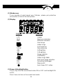
 1
1
-
 2
2
-
 3
3
-
 4
4
-
 5
5
-
 6
6
-
 7
7
-
 8
8
-
 9
9
-
 10
10
-
 11
11
-
 12
12
-
 13
13
-
 14
14
-
 15
15
-
 16
16
-
 17
17
-
 18
18
-
 19
19
-
 20
20
-
 21
21
-
 22
22
-
 23
23
-
 24
24
-
 25
25
-
 26
26
-
 27
27
-
 28
28
-
 29
29
-
 30
30
-
 31
31
-
 32
32
-
 33
33
-
 34
34


The TFA 31.2000 is a data logger sound level meter designed to measure and record sound levels in various environments for up to 50 hours of operation. It features a digital display for easy reading and allows users to select between A and C frequency weighting as well as fast and slow time weighting to adapt to different measurement scenarios. With its compact size and lightweight design, it is ideal for on-the-go sound level monitoring. It can store up to 32,000 data points, which can be easily transferred to a PC via RS232 interface for further analysis.
Ask a question and I''ll find the answer in the document
Finding information in a document is now easier with AI
in other languages
- Deutsch: TFA 31.2000 Benutzerhandbuch
Related papers
-
TFA Sound Level Meter SL328 User manual
-
-
-
-
-
-
-
Dostmann LOG210 User manual
-
TFA Log32 TH Operating instructions
-
TFA Temperature and Humidity Data LoggerOG20 User manual

