ESAB ESAB EMP 205ic AC/DC User manual
- Category
- Welding System
- Type
- User manual
This manual is also suitable for

0463 703 001GB 20190927 Valid for: serial no. 937-xxx-xxxx
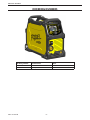
EMP 205ic AC/DC
Instruction manual

0463 703 001GB 20190927 Valid for: serial no. 937-xxx-xxxx
!
!
WARNING
Read and understand this entire Manual and your employer’s safety practices
before installing, operating, or servicing the equipment.
While the information contained in this Manual represents the Manufacturer's best
judgment, the Manufacturer assumes no liability for its use.
Welding System
EMP 205ic AC/DC
Operating Manual Number 0463 703 001
Published by:
ESAB Group Inc.
2800 Airport Rd.
Denton, TX 76208
(940) 566-2000
www.esab.eu
Copyright 2019 by ESAB
All rights reserved.
Reproduction of this work, in whole or in part, without written permission of the publisher
is prohibited.
The publisher does not assume and hereby disclaims any liability to any party for any loss
or damage caused by any error or omission in this Manual, whether such error results from
negligence, accident, or any other cause.
Original Publication Date: 09/27/2019
Revision Date:
Record the following information for Warranty purposes:
Where Purchased:_______________________________ __________________
Purchase Date:__________________________________ _________________
Power Supply Serial #:___________________________ __________________
ESAB operates a policy of continuous improvement. We therefore reserve the right to make
changes and improvements to any of our products without notice.

0463 703 001GB 20190927 Valid for: serial no. 937-xxx-xxxx
Be sure this information reaches the operator.
You can get extra copies through your supplier.
CAUTION
These INSTRUCTIONS are for experienced operators. If you are not fully familiar with the
principles of operation and safe practices for arc welding and cutting equipment, we urge
you to read our booklet, “Precautions and Safe Practices for Arc Welding, Cutting, and
Gouging,” Form 52-529. Do NOT permit untrained persons to install, operate, or maintain
this equipment. Do NOT attempt to install or operate this equipment until you have read
and fully understand these instructions. If you do not fully understand these instructions,
contact your supplier for further information. Be sure to read the Safety Precautions be-
fore installing or operating this equipment.
USER RESPONSIBILITY
This equipment will perform in conformity with the description thereof contained in this
manual and accompanying labels and/or inserts when installed, operated, maintained and
repaired in accordance with the instructions provided. This equipment must be checked periodi-
cally. Malfunctioning or poorly maintained equipment should not be used. Parts that are broken,
missing, worn, distorted or contaminated should be replaced immediately. Should such repair
or replacement become necessary, the manufacturer recommends that a telephone or written
request for service advice be made to the Authorized Distributor from whom it was purchased.
This equipment or any of its parts should not be altered without the prior written approv-
al of the manufacturer. The user of this equipment shall have the sole responsibility for any
malfunction which results from improper use, faulty maintenance, damage, improper repair or
alteration by anyone other than the manufacturer or a service facility designated by the manu-
facturer.
!
READ AND UNDERSTAND THE INSTRUCTION MANUAL BEFORE INSTALLING OR OPERATING.
PROTECT YOURSELF AND OTHERS!


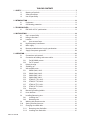
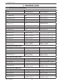
TABLE OF CONTENTS
0463 703 001GB
1 SAFETY .................................................................................................................................7
1.1 Meaning of symbols.............................................................................................................7
1.2 Safety precautions ................................................................................................................7
1.3 User responsibility ............................................................................................................. 11
2 INTRODUCTION
................................................................................................................13
2.1 Equipment ............................................................................................................................13
2.2 Overheating protection ...................................................................................................13
3 TECHNICAL DATA
.............................................................................................................. 14
3.1 EMP 205ic AC/DC specications ................................................................................... 14
4 INSTALLATION
...................................................................................................................16
4.1 User’s responsibility .......................................................................................................... 16
4.2 Lifting instructions ............................................................................................................16
4.3 Location .................................................................................................................................17
4.3.1 Assessment of area ..................................................................................................17
4.4 High frequency interference ..........................................................................................18
4.5 Main supply ..........................................................................................................................19
4.6 Recommended electrical-supply specications .....................................................20
4.7 Supply from power generators .....................................................................................20
5 OPERATION
........................................................................................................................21
5.1 Connections and controls ...............................................................................................22
5.2 Connection of welding and return cables ................................................................23
5.2.1 For MIG/MMA process ............................................................................................23
5.2.2 For TIG process .......................................................................................................... 23
5.3 Polarity change ................................................................................................................... 23
5.4 Shielding gas ....................................................................................................................... 24
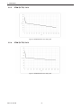
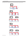
5.5 Volt-ampere curves ........................................................................................................... 24
5.5.1 SMAW (Stick) 120 V ..................................................................................................24
5.5.2 SMAW (Stick) 230 V ..................................................................................................24
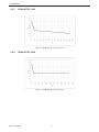
5.5.3 GMAW (MIG) 120 V ...................................................................................................25
5.5.4 GMAW (MIG) 230 V ...................................................................................................25
5.5.5 GTAW (DC TIG) 120 V ............................................................................................... 26
5.5.6 GTAW (DC TIG) 230 V ............................................................................................... 26
5.5.7 GTAW (AC TIG) 120 V ............................................................................................... 27
5.5.8 GTAW (AC TIG) 230 V ............................................................................................... 27
5.5.9 Duty cycle ...................................................................................................................28
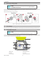
5.6 Removing/installing bobbin ..........................................................................................29
5.7 Liner selection .....................................................................................................................29
5.8 Installing/Removing wire ................................................................................................29
5.8.1 Installing wire ............................................................................................................ 30
5.8.2 Removing wire .......................................................................................................... 31
5.9 Welding with aluminum wire ........................................................................................ 31
5.10 Setting wire-feed pressure .............................................................................................32
5.11 Changing wire-feed roller ...............................................................................................33
5.11.1 Removing wire-feed roller .................................................................................... 34
5.11.2 Installing wire-feed roller ...................................................................................... 35

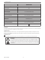
TABLE OF CONTENTS
0463 703 001GB
6 CONTROL PANEL ............................................................................................................... 36
6.1 How to navigate ................................................................................................................. 36
6.2 EMP 205ic AC/DC Home screen ....................................................................................36
6.2.1 sMIG mode .................................................................................................................36
6.2.2 Manual MIG mode ................................................................................................... 37
6.2.3 Gasless ux cored wire mode ..............................................................................37
6.2.4 MMA mode .................................................................................................................38
6.2.5 DC TIG mode .............................................................................................................. 38
6.2.6 AC TIG mode ..............................................................................................................39
6.3 Settings ..................................................................................................................................40
6.4 User manual information ................................................................................................ 40
6.5 Icon reference guide ......................................................................................................... 40
7 TIG WELDING OPERATION
...............................................................................................43
7.1 DC TIG Welding ................................................................................................................... 43
7.1.1 DC TIG Pulse ............................................................................................................... 44
7.1.2 DC TIG Dual Current ................................................................................................ 51
7.2 AC TIG Welding ...................................................................................................................53
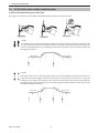
7.3 DC TIG Lift Arc and 2-stroke/4-stroke Illustration ...................................................57
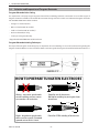
7.4 Selection and Preparation of Tungsten Electrodes................................................58
8 MAINTENANCE
..................................................................................................................59
8.1 Routine maintenance ....................................................................................................... 59
8.2 Power source and wire-feeder maintenance ...........................................................60
8.2.1 Wire-feeder assembly cleaning ...........................................................................61
8.3 EMP-unit power side maintenance .............................................................................62
8.4 Torch liner maintenance ..................................................................................................62
8.4.1 Torch liner cleaning .................................................................................................62
9 TROUBLESHOOTING
.........................................................................................................63
9.1 Preliminary checks .............................................................................................................63
9.2 User interface (UI) software displayed error codes ................................................64
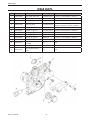
10 ORDERING SPARE/WEAR PARTS
...................................................................................65
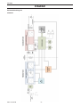
DIAGRAM
...............................................................................................................................66
ORDERING NUMBERS
...........................................................................................................67
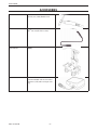
WEAR PARTS
..........................................................................................................................68
ACCESSORIES
.........................................................................................................................69
REPLACEMENTS PARTS
........................................................................................................70

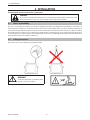
1 SAFETY
0463 703 001
GB
-7-
1 SAFETY
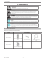
1.1 Meaning of symbols
As used throughout this manual: Means Attention! Be Alert!
NOTE!
An operation, procedure, or background information which requires additional em-
phasis or is helpful in ecient operation of the system.
CAUTION
A procedure which, if not properly followed, may cause damage to the equipment.
!!
WARNING
A procedure which, if not properly followed, may cause injury to the operator or others
in the operating area.
WARNING
Gives information regarding possible electrical shock injury. Warnings will be enclosed
in a box such as this.
WARNING
Gives information regarding possible electrical shock injury.
1.2 Safety precautions
!!
WARNING!
These Safety Precautions are for your protection. They summarize precautionary information
from the references listed in Additional Safety Information section.
Before performing any installation or operating procedures, be sure to read and follow the
safety precautions listed below as well as all other manuals, material safety data sheets, labels,
etc. Failure to observe Safety Precautions can result in injury or death.
PROTECT YOURSELF AND OTHERS
Some welding, cutting and gouging processes are noisy and require ear protection. The arc, like the
sun, emits ultraviolet (UV) and other radiation and can injure skin and eyes. Hot metal can cause
burns. Training in the proper use of the processes and equipment is essential to prevent accidents.
Therefore:
1. Wear a welding helmet tted with a proper shade of lter to protect you face and eyes when welding or watching.
2. Always wear safety glasses with side shields in any work area, even if welding helmets face shields and goggles are
also required.
3. Use a face shield tted with the correct lter and cover plates to protect your eyes, face, neck and ears from sparks
and rays of the arc when operating or observing operations. Warn bystanders not to watch the arc and not to expose
themselves to the rays of the electric-arc or hot metal.
4. Wear ameproof gauntlet type gloves, heavy long-sleeve shirt, cu less trousers, high-topped shoes and a welding
helmet or cap for protection, to protect against arc rays and hot sparks or hot metal. A ameproof apron may also
be desirable as protection against radiated heat and sparks.
5. Hot sparks or metal can lodge in rolled up sleeves, trouser cus, or pockets. Sleeves and collars should be kept
buttoned and open pockets eliminated from the front of clothing.

1 SAFETY
0463 703 001
GB
-8-
6. Protect other personnel from arc rays and hot sparks with a suitable non-ammable partition or curtains.
7. Use goggles over safety glasses when chipping slag or grinding. Chipped slag may be hot and can y for long
distances. Bystanders should also wear goggles over safety glasses.
FIRES AND EXPLOSIONS
Heat from ames and arcs can start res. Hot slag or sparks can also cause res and explosions.
Therefore:
1. Protect yourself and others from ying sparks and hot metal.
2. Remove all combustible materials well away from the work area or cover the materials with a protective non-
ammable covering. Combustible materials include wood, cloth, sawdust, liquid and gas fuels, solvents, paints and
coatings paper, etc.
3. Hot sparks or hot metal can fall through cracks or crevices in oors or wall openings and cause a hidden smoldering
re or res on the oor below. Make certain that such openings are protected from hot sparks and metal.
4. Do not weld, cut or perform other hot work until the work piece has been completely cleaned so that there are
no substances on the work piece which might produce ammable or toxic vapors. Do not do hot work on closed
containers. They may explode.
5. Have re extinguishing equipment handy for instant use, such as a garden hose, water pail, sand bucket, or portable
re extinguisher. Be sure you are trained in its use.
6. Do not use equipment beyond its ratings. For example, overloaded welding cable can overheat and create a re
hazard.
7. After completing operations, inspect the work area to make certain there are no hot sparks or hot metal which
could cause a later re. Use re watchers when necessary.
ELECTRICAL SHOCK
Contact with live electrical parts and ground can cause severe injury or death. DO NOT use AC
welding current in damp areas, if movement is conned, or if there is danger of falling. Therefore:
1. Be sure the power source frame (chassis) is connected to the ground system of the input power.
2. Connect the workpiece to a good electrical ground.
3. Connect the work cable to the workpiece. A poor or missing connection can expose you or others to a fatal shock.
4. Use well-maintained equipment. Replace worn or damaged cables.
5. Keep everything dry, including clothing, work area, cables, torch/electrode holder and power source.
6. Make sure that all parts of your body are insulated from work and from ground.
7. Do not stand directly on metal or the earth while working in tight quarters or a damp area; stand on dry boards or
an insulating platform and wear rubber-soled shoes.
8. Put on dry, hole-free gloves before turning on the power.
9. Turn OFF the power before removing your gloves.
10. Refer to ANSI/ASC Standard Z49.1 for specic grounding recommendations. Do not mistake the work lead for a
ground cable.
ELECTRIC AND MAGNETIC FIELDS
May be dangerous. Electric current owing through any conductor causes localized Electric and
Magnetic Fields (EMF). Welding and cutting current creates EMF around welding cables and weld-
ing machines. Therefore:
1. Welders having pacemakers should consult their physician before welding. EMF may interfere with some
pacemakers.
2. Exposure to EMF may have other health eects which are unknown.
3. Welders should use the following procedures to minimize exposure to EMF:
a) Route the electrode and work cables together. Secure them with tape when possible.
b) Never coil the torch or work cable around your body.
c) Do not place your body between the torch and work cables. Route cables on the same side of your body.
d) Connect the work cable to the workpiece as close as possible to the area being welded.
e) Keep welding power source and cables as far away from your body as possible.

1 SAFETY
0463 703 001
GB
-9-
FUMES AND GASES
Fumes and gases, can cause discomfort or harm, particularly in conned spaces. Shielding gases
can cause asphyxiation. Therefore:
1. Keep your head out of the fumes. Do not breathe the fumes and gases.
2. Always provide adequate ventilation in the work area by natural or mechanical means. Do not weld, cut or gouge
on materials such as galvanized steel, stainless steel, copper, zinc, lead beryllium or cadmium unless positive me-
chanical ventilation is provided. Do not breathe fumes from these materials.
3. Do not operate near degreasing and spraying operations. The heat or arc can react with chlorinated hydrocarbon
vapors to form phosgene, a highly toxic gas and other irritant gases.
4. If you develop momentary eye, nose or throat irritation while operating, this is an indication that ventilation is not
adequate. Stop work and take necessary steps to improve ventilation in the work area. Do not continue to operate
if physical discomfort persists.
5. Refer to ANSI/ASC Standard Z49.1 for specic ventilation recommendations.
6. WARNING: This product when used for welding or cutting, produces fumes or gases which contain chemicals
known to the State of California to cause birth defects and in some cases cancer (California Health & Safety Code
§25249.5 et seq.)
CYLINDER HANDLING
Cylinders, if mishandled, can rupture and violently release gas. Sudden rupture of cylinder valve
or relief device can injure or kill. Therefore:
1. Locate cylinders away from heat, sparks and ames. Never strike an arc on a cylinder.
2. Use the proper gas for the process and use the proper pressure reducing regulator designed to operate from the
compressed gas cylinder. Do not use adaptors. Maintain hoses and ttings in good condition. Follow manufacturer's
operating instructions for mounting regulator to a compressed gas cylinder.
3. Always secure cylinders in an upright position by chain or strap to suitable hand trucks, undercarriages, benches,
wall, post or racks. Never secure cylinders to work tables or xtures where they may become part of an electrical
circuit.
4. When not in use, keep cylinder valves closed. Have valve protection cap in place if regulator is not connected. Secure
and move cylinders by using suitable hand trucks.
MOVING PARTS
Moving parts, such as fans, rotors and belts can cause injury. Therefore:
1. Keep all doors, panels and covers closed and securely in place.
2. Stop engine before installing or connecting unit.
3. Have only qualied people remove covers for maintenance and troubleshooting as necessary
4. To prevent accidental starting of equipment during service, disconnect negative (-) battery cable from battery.
5. Keep hands, hair, loose clothing and tools away from moving parts.
6. Reinstall panels or covers and close doors when service is nished and before starting engine.
!!
WARNING!
FALLING EQUIPMENT CAN INJURE
• Only use lifting eye to lift unit. Do NOT use running gear, gas cylinders or any other
accessories.
• Use equipment of adequate capacity to lift and support unit.
• If using lift forks to move unit, be sure forks are long enough to extend beyond opposite
side of unit.
• Keep cables and cords away from moving vehicles when working from an aerial
location.

1 SAFETY
0463 703 001
GB
-10-
!!
WARNING!
EQUIPMENT MAINTENANCE
Faulty or improperly maintained equipment can cause injury or death. Therefore:
1. Always have qualied personnel perform the installation, troubleshooting and mainte-
nance work. Do not perform any electrical work unless you are qualied to perform such
work.
2. Before performing any maintenance work inside a power source, disconnect the power
source from the incoming electrical power.
3. Maintain cables, grounding wire, connections, power cord and power supply in safe
working order. Do not operate any equipment in faulty condition.
4. Do not abuse any equipment or accessories. Keep equipment away from heat sources such
as furnaces, wet conditions such as water puddles, oil or grease, corrosive atmospheres
and inclement weather.
5. Keep all safety devices and cabinet covers in position and in good repair.
6. Use equipment only for its intended purpose. Do not modify it in any manner.
!!
CAUTION!
ADDITIONAL SAFETY INFORMATION
For more information on safe practices for electric arc welding and cutting equip-
ment, ask your supplier for a copy of “Precautions and Safe Practices for Arc
Welding, Cutting and Gouging”, Form 52-529.
The following publications are recommended to you:
1. ANSI/ASC Z49.1 - “Safety in Welding and Cutting”
2. AWS C5.5 - “Recommended Practices for Gas Tungsten Arc Welding”
3. AWS C5.6 - “Recommended Practices for Gas Metal Arc welding”
4. AWS SP - “Safe practices” - Reprint, Welding Handbook
5. ANSI/AWS F4.1 - “Recommended Safe Practices for Welding and Cutting of Containers
That Have Held Hazardous Substances”
6. OSHA 29 CFR 1910 - “Safety and health standards”
7. CSA W117.2 - “Code for safety in welding and cutting”
8. NFPA Standard 51B, “Fire Prevention During Welding, Cutting, and Other Hot Work"
9. CGA Standard P-1, “Precautions for Safe Handling of Compressed Gases in Cylinders”
10. ANSI Z87.1, "Occupational and Educational Personal Eye and Face Protection Devices"

1 SAFETY
0463 703 001
GB
-11-
1.3 User responsibility
Users of ESAB welding and plasma cutting equipment have the ultimate responsibility for ensuring that anyone who works
on or near the equipment observes all the relevant safety precautions. Safety precautions must meet the requirements
that apply to this type of welding or plasma cutting equipment. The following recommendations should be observed in
addition to the standard regulations that apply to the workplace.
All work must be carried out by trained personnel well acquainted with the operation of the welding or plasma cutting
equipment. Incorrect operation of the equipment may lead to hazardous situations which can result in injury to the
operator and damage to the equipment.
1. Anyone who uses welding or plasma cutting equipment must be familiar with:
- its operation
- location of emergency stops
- its function
- relevant safety precautions
- welding and / or plasma cutting
2. The operator must ensure that:
- no unauthorized person stationed within the working area of the equipment when it is started up.
- no one is unprotected when the arc is struck.
3. The workplace must:
- be suitable for the purpose
- be free from drafts
4. Personal safety equipment:
- Always wear recommended personal safety equipment, such as safety glasses, ame proof
clothing, safety gloves.
- Do not wear loose tting items, such as scarves, bracelets, rings, etc., which could become
trapped or cause burns.
5. General precautions:
- Make sure the return cable is connected securely.
- Work on high voltage equipment may only be carried out by a qualied electrician.
- Appropriate re extinguishing equipment must be clearly marked and close at hand.
- Lubrication and maintenance must not be carried out on the equipment during operation.
Dispose of electronic equipment at the recycling facility!
In observance of European Directive 2002/96/EC on Waste Electrical and Electronic Equipment
and its implementation in accordance with national law, electrical and/or electronic equipment
that has reached the end of its life must be disposed of at a recycling facility.
As the person responsible for the equipment, it is your responsibility to obtain information on
approved collection stations.
For further information contact the nearest ESAB dealer.
ESAB can provide you with all necessary cutting protection and accessories.

1 SAFETY
0463 703 001
GB
-12-
WARNING
Arc welding and cutting can be injurious to yourself and others. Take
precautions when welding and cutting. Ask for your employer's safety
practices which should be based on manufacturers' hazard data.
ELECTRIC SHOCK - Can kill.
- Install and earth (ground) the welding or plasma cutting unit in accordance with applicable standards.
- Do not touch live electrical parts or electrodes with bare skin, wet gloves or wet clothing.
- Insulate yourself from earth and the workpiece.
- Ensure your working stance is safe.
FUMES AND GASES - Can be dangerous to health.
- Keep your head out of the fumes.
- Use ventilation, extraction at the arc, or both, to take fumes and gases away from your breathing zone and the
general area.
ARC RAYS - Can injure eyes and burn skin.
- Protect your eyes and body. Use the correct welding / plasma cutting screen and lter lens and wear protective cloth-
ing.
- Protect bystanders with suitable screens or curtains.
FIRE HAZARD
- Sparks (spatter) can cause re. Make sure therefore that there are no inammable materials nearby.
NOISE - Excessive noise can damage hearing.
- Protect your ears. Use earmus or other hearing protection.
- Warn bystanders of the risk.
MALFUNCTION - Call for expert assistance in the event of malfunction.
READ AND UNDERSTAND THE INSTRUCTION MANUAL BEFORE INSTALLING OR OPERATING.
PROTECT YOURSELF AND OTHERS!
WARNING
Do not use the power source for thawing frozen pipes.
CAUTION
Class A equipment is not intended for use in residential loca-
tions where the electrical power is provided by the public low-
voltage supply system. There may be potential diculties in
ensuring electromagnetic compatibility of class A equipment
in those locations, due to conducted as well as radiated distur-
bances.
CAUTION
This product is solely intended for metal removal. Any other use may result in
personal injury and / or equipment damage.
CAUTION
Read and understand the instruction manual before installing
or operating.
!

2 INTRODUCTION
0463 703 001GB
-13-
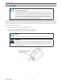
2 INTRODUCTION
The ESAB EMP 205ic AC/DC product is a new generation of multi-process (MIG/Stick/TIG:AC or DC) welding power sources.
All Rebel power sources are designed to match the needs of the user. They are tough, durable, and portable, providing
excellent arc performance across a variety of welding applications.
The EMP family features a 11 cm (4.3 in.) color TFT (Thin Film Transistor) user interface (UI) display which provides quick
and easy selection of weld process and parameters, suitable for both newly trained and intermediate-level users. For more
advanced users, any number of functions could be introduced and customized to give maximum exibility.
ESAB accessories for the product can be found in the "ACCESSORIES" chapter of this manual.
2.1 Equipment
The ESAB EMP 205ic AC/DC power source is supplied with:
• ESAB EMP 205ic AC/DC power source
• ESAB MXL 201 MIG torch, 3 m (10 ft) with contact tips M6 for 0.8 mm and 1.0 mm
• ESAB SR-B 26 TIG Torch with accessories
• Gas hose, 4.5 m (14.8 ft), Quick connector
• MMA welding cable kit, 3 m (10 ft)
• Return cable kit 3 m (10 ft)
• Drive roll
0.6 / 0.8 mm (0.023 in. / 0.030 in.) Cored, Steel and Stainless wire (installed on drive system)
0.8 / 1.0 mm (0.030 in. / 0.040 in.) Cored, Steel and Stainless wire (in accessory box)
• Guide tube
1.0 mm - 1.2 mm (0.040 in. - 0.045 in.) (installed on drive system)
0.6 mm - 0.8 mm (0.023 in. - 0.030 in.) (in accessory box)
• Mains cable 3 m (10 ft), xed with plug
• Safety manual
• USB with Operator's Manual
• Material thickness guide
2.2 Overheating protection
CAUTION
This unit is equipped with overheating protection for its power supply.
The welding power source has overheating protection that operates if the internal temperature becomes
too high. When this occurs, the welding current is interrupted, and an overheating symbol appears on the
display. The overheating protection resets automatically when the temperature has returned to normal
working temperature.
The procedures to recover the overheating condition:
• Allow system to cool, Rebel recovers on its own.
• Allow system to fully cool to point when fans stop before additional welding.
• If not reaching full 'Duty Cycle' and both fans operating, and no obstruction then return from service.

3 TECHNICAL DATA
0463 703 001GB
-14-
3 TECHNICAL DATA
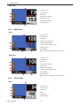
3.1 EMP 205ic AC/DC specications
EMP 205ic AC/DC
Voltage 230 V,1 ph, 50/60 Hz 120 V, 1 ph, 50/60 Hz
Primary current
I
max.
GMAW - MIG 29.6 A
Breaker 20 A: 27.1 A
Breaker 15 A: 20.2 A
I
max.
GTAW - DC TIG 24.0 A Breaker 15 A: 20.7 A
I
max.
GTAW - AC TIG 26.5 A Breaker 15 A: 21.4 A
I
max.
SMAW - Stick 28.3 A Breaker 15 A: 20.5 A
I
e.
GMAW - MIG 14.8 A
Breaker 20 A: 15.8 A
Breaker 15 A: 14.5 A
I
e.
GTAW - DC TIG 12 A Breaker 15 A: 14.3 A
I
e.
GTAW - AC TIG 13.3 A Breaker 15 A: 14.9 A
I
e.
SMAW - Stick 14.1 A Breaker 15 A: 14.4 A
Permissible load in GMAW - MIG
100% duty cycle* 110 A (V
out
= 19.5 V)
Breaker 15 A: 65 A (V
out
= 17.25 V)
Breaker 20 A: 70 A (V
out
= 17.5 V)
60% duty cycle* 125 A (V
out
= 20.25 V)
Breaker 15 A: 85 A (V
out
= 18.25 V)
Breaker 20 A: 90 A (V
out
= 18.5 V)
40% duty cycle* 150 A (V
out
= 21.5 V) Breaker 15 A: 90 A (V
out
= 18.5 V)
25% duty cycle* 205 A (V
out
= 24.25 V) -
20% duty cycle* - Breaker 20 A: 115 A (V
out
= 19.75 V)
Setting range (DC)
15 A (V
out
= 14.75 V) -
235 A (V
out
= 26.0 V)
15 A (V
out
= 14.75 V) -
130 A (V
out
= 20.5 V)
Permissible load in GTAW - DC TIG
100% duty cycle* 110 A (V
out
= 14.4 V) Breaker 15 A: 80 A (V
out
= 13.2 V)
60% duty cycle* 125 A (V
out
= 15.0 V) Breaker 15 A: 100 A (V
out
= 14.0 V)
40% duty cycle* - Breaker 15 A: 110 A (V
out
= 14.4 V)
25% duty cycle* 205 A (V
out
= 18.2 V)
Setting range (DC)
5 A (V
out
= 10.2 V) -
205 A (V
out
= 18.2 V)
5 A (V
out
= 10.2 V) -
130 A (V
out
= 15.2 V)
Permissible load in GTAW - AC TIG
100% duty cycle* 110 A (V
out
= 14.4 V) Breaker 15 A: 75 A (V
out
= 13.0 V)
60% duty cycle* 125 A (V
out
= 15.0 V) Breaker 15 A: 95 A (V
out
= 13.8 V)
40% duty cycle* - Breaker 15 A: 105 A (V
out
= 14.2 V)
25% duty cycle* 205 A (V
out
= 18.2 V)
Setting range (AC)
5 A (V
out
= 10.2 V) -
205 A (V
out
= 18.2 V)
5 A (V
out
= 10.2 V) -
130 A (V
out
= 15.2 V)
Permissible load in SMAW - Stick
100% duty cycle* 100 A (V
out
= 24 V) 55 A (V
out
= 22.2 V)
60% duty cycle* 125 A (V
out
= 25 V) 70 A (V
out
= 22.8 V)
40% duty cycle* - 75 A (V
out
= 23.0 V)
25% duty cycle* 170 A (V
out
= 26.8 V) -
Setting range (DC)
16 A (V
out
= 20.6 V) -
180 A (V
out
= 27.2 V)
16 A (V
out
= 20.6 V) -
130 A (V
out
= 25.2 V)

3 TECHNICAL DATA
0463 703 001GB
-15-
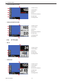
EMP 205ic AC/DC
Open circuit voltage (OCV)
VRD deactivated 68 V
VRD activated 35V
Eciency 78%
Power factor 0.98
Wire-feed speed 2-12.1 m/min (80-475 in./min)
Wire diameter
Mild steel solid wire 0.6 - 0.9 mm (0.023 - 0.035 in.)
Stainless steel solid wire 0.8 - 0.9 mm (0.030 - 0.035 in.)
Flux-cored wire 0.8 - 1.1 mm (0.030 - 0.045 in.)
Aluminium 0.8 - 1.2 mm (0.030 - 0.047 in.)
Bobbin size 100-200 mm (4- 8 in.)
Dimensions L×W×H 548 × 229 × 406 mm (23 × 9 × 16 in.)
Weight 25.5 kg ( 56 lb,)
Operating temperature -10 ° to + 40 °C (14 ° to 104 °F)
Enclosure class** IP23S
Application classication***
S
*Duty cycle
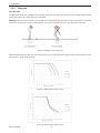
The duty cycle refers to the time as a percentage of a ten-minute period that you can weld or cut at a certain load without
overloading. The duty cycle is valid for 40 °C (104 °F) or below.
**Enclosure class
The IP code indicates the enclosure class, i.e. the degree of protection against penetration by solid objects or water.
Equipment marked IP 23S is intended for indoor and outdoor use; however, should not be operated in precipitation.
***Application class
S
This symbol indicates that the power source is designed for use in areas with increased electrical hazard.
!!
WARNING!
The welding circuit may or may not be earthed for safety reasons. Changing the earthing
arrangements should only be authorized by a person who is competent to assess whether
the changes will increase the risk of injury. For example: by allowing parallel welding current
return paths which may damage the earth circuits of other equipment or cause injury/death
to individuals.

4 INSTALLATION
0463 703 001GB
-16-
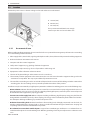
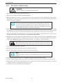
4 INSTALLATION
The installation must be carried out by a professional.
CAUTION!
This product is intended for industrial use. In a domestic environment, this product may cause
radio interference. It is the user's responsibility to take adequate precautions.
4.1 User’s responsibility
The user is responsible for installing and using the welding equipment according to the manufacturer’s instructions. If
electromagnetic disturbances are detected, then it shall be the responsibility of the user of the welding equipment to
resolve the situation with the technical assistance of the manufacturer. This remedial action may be as simple as earthing
the welding circuit. In other cases, it could involve constructing an electromagnetic screen enclosing the welding power
source and the work, complete with associated input lters. In all cases, electromagnetic disturbances shall be reduced to
the point where they are no longer troublesome.
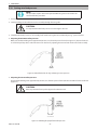
4.2 Lifting instructions
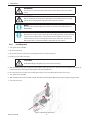
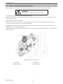
The power source can be lifted using any of the handles.
!!
WARNING!
Secure the equipment - particularly if the
ground is uneven or sloping.

4 INSTALLATION
0463 703 001GB
-17-
4.3 Location
Position the power source so that its cooling air inlets and outlets are not obstructed.
4.3.1 Assessment of area
Before installing welding equipment, the user/installer shall assess potential electromagnetic problems in the surrounding
area. The following shall be considered:
1. Other supply cables, control cables, signaling and telephone cables; above, below and adjacent to the welding equipment.
2. Radio and television transmitters and receivers.
3. Computer and other control equipment.
4. Safety critical equipment, e.g. guarding of industrial equipment.
5. The health of people around, e.g. the use of pacemakers and hearing aids.
6. Equipment used for calibration and measurement.
7. The time of day that welding or other activities are to be carried out.
8. The immunity of other equipment in the environment, the user shall ensure that other equipment being used in the
environment is compatible. This may require additional protection measures.
9. The size of the surrounding area to be considered will depend on the structure of the building and other activities that
are taking place. The surrounding area may extend beyond the boundaries of the premises.
Interference may be transmitted by a high frequency initiated or stabilized arc welding power source in the following ways:
• Direct radiation: Radiation from the equipment can occur if the case is metal and is not properly grounded. It can occur
through apertures such as open access panels. The shielding of the high frequency unit in the power source will prevent
direct radiation if the equipment is properly grounded.
• Transmission via the supply lead: Without adequate shielding and ltering, high frequency energy may be fed to the
wiring within the installation (mains) by direct coupling. The energy is then transmitted by both radiation and conduc-
tion. Adequate shielding and ltering is provided in the power source.
• Radiation from welding leads: Radiated interference from welding leads, although pronounced near the leads, di-
minishes rapidly with distance. Keeping leads as short as possible will minimize this type of interference. Looping and
suspending of leads should be avoided wherever possible.
• Re-radiation from unearthed metallic objects: A major factor contributing to interference is re-radiation from un-
earthed metallic objects close to the welding leads. Eective grounding of such objects will prevent re-radiation in most
cases.
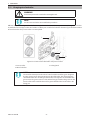
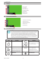
A. 152 mm (6 in.)
B. 100 mm (4 in.)
C. 152 mm (6 in.)
If in a permanent installation leave enough
room to open door and access bobbin side.

4 INSTALLATION
0463 703 001GB
-18-
4.4 High frequency interference
!!
WARNING!
The high frequency section of this machine has an output like a radio transmitter.
The power source should NOT be used near blasting operations due to the danger of
premature ring.
!
!
WARNING!
Operation close to computer installations may cause computer malfunction.
!
!
WARNING!
HIGH FREQUENCY FIELDS CAN BE DANGEROUS TO HEALTH. Extra precautions may be
required when this welding power source is used in a domestic situation. Welders with
medical pacemakers should consult their doctor before welding. EMF may interfere with
some pacemakers.
!
!
WARNING!
Equipotential bonding:
Bonding of all metallic components in the welding installation and adjacent to it might
be considered. However, metallic components bonded to the work piece will increase the
risk that the operator could receive a shock by touching the metallic components and the
electrode at the same time. The operator should be insulated from all such bonded metallic
components.
!!
WARNING!
Earthing/grounding of the work place:
Care should be taken to prevent the earthing of the work piece increasing the risk of injury
to users, or damage to other electrical equipment. Changing the earthing arrangements
should only be authorized by a person who is competent to assess whether the changes will
increase the risk of injury.
!
!
WARNING!
The importance of correct installation of high frequency welding equipment cannot be
overemphasized. Interference due to high frequency initiated or stabilized arc is almost
invariably traced to improper installation. A duly authorized person such as a properly
licensed electrician should perform the installation to avoid injury, death, or any equipment
damage.

4 INSTALLATION
0463 703 001GB
-19-
4.5 Main supply
NOTE!
Mains supply requirements
This equipment complies with IEC 61000-3-12 provided that the short-circuit power is
greater than or equal to S
scmin
at the interface point between the user's supply and the
public system. It is the responsibility of the installer or user of the equipment to ensure,
by consultation with the distribution network operator if necessary, that the equipment
is connected only to a supply with a short-circuit power greater than or equal to S
scmin
.
Refer to the technical data in the TECHNICAL DATA chapter.
The supply voltage should be 230 V AC ±10% or 120 V AC ±10%. Too low supply voltage may cause poor welding perfor-
mance. Too high supply voltage will cause components to overheat and possibly fail. Contact the local electric utility for
information about the type of electrical service available, how proper connections should be made, and inspection required.
The welding power source must be:
• Correctly installed, if necessary, by a qualied electrician.
• Correctly earthed (electrically) in accordance with local regulations.
• Connected to the correct size power point and fuse as tables below.
NOTE!
Use the welding power source in accordance with the relevant national regulations.
CAUTION!
Disconnect input power and secure employing "Lock-out/Tagging" procedures. Ensure
input power line disconnect switch is locked (Lock-out/Tagging) in the "Open" position
BEFORE removing input power fuses. Connecting/disconnecting should be carried out
by competent persons.

4 INSTALLATION
0463 703 001GB
-20-
4.6 Recommended electrical-supply specications
!!
WARNING!
An electrical shock or re hazard is probable if the following electrical service guide
recommendations are not followed. These recommendations are for a dedicated branch
circuit sized for the rated output and duty cycle of the welding power source.
Recommended electrical supply specications: 120–230 V, 1 – 50/60 Hz
Specication 230 V AC 120 V AC
Input current at maximum output 33 A 30 A
Maximum recommended fuse* or circuit breaker rating
*Time delay fuse UL class RK5, refer to UL 248
40 A 30 A
Maximum recommended fuse* or circuit breaker rating
Normal operating UL class K5, refer to UL 248
50 A 50 A
Minimum recommended cord size 2.5 mm (13 AWG) 2.5 mm (13 AWG)
Maximum recommended extension cord length 15 m (50 ft) 8 m (25 ft)
Minimum recommended grounding conductor size 2.5 mm (13 AWG) 2.5 mm (13 AWG)
4.7 Supply from power generators
The power source can be supplied from dierent types of generators. However, some generators may not provide sucient
power for the welding power source to operate correctly.
Generators with Automatic Voltage Regulation (AVR) or with equivalent or better type of regulation, with rated power of
minimum 8 kW 1 phase, are recommended.
Page is loading ...
Page is loading ...
Page is loading ...
Page is loading ...
Page is loading ...
Page is loading ...
Page is loading ...
Page is loading ...
Page is loading ...
Page is loading ...
Page is loading ...
Page is loading ...
Page is loading ...
Page is loading ...
Page is loading ...
Page is loading ...
Page is loading ...
Page is loading ...
Page is loading ...
Page is loading ...
Page is loading ...
Page is loading ...
Page is loading ...
Page is loading ...
Page is loading ...
Page is loading ...
Page is loading ...
Page is loading ...
Page is loading ...
Page is loading ...
Page is loading ...
Page is loading ...
Page is loading ...
Page is loading ...
Page is loading ...
Page is loading ...
Page is loading ...
Page is loading ...
Page is loading ...
Page is loading ...
Page is loading ...
Page is loading ...
Page is loading ...
Page is loading ...
Page is loading ...
Page is loading ...
Page is loading ...
Page is loading ...
Page is loading ...
Page is loading ...
Page is loading ...
-
 1
1
-
 2
2
-
 3
3
-
 4
4
-
 5
5
-
 6
6
-
 7
7
-
 8
8
-
 9
9
-
 10
10
-
 11
11
-
 12
12
-
 13
13
-
 14
14
-
 15
15
-
 16
16
-
 17
17
-
 18
18
-
 19
19
-
 20
20
-
 21
21
-
 22
22
-
 23
23
-
 24
24
-
 25
25
-
 26
26
-
 27
27
-
 28
28
-
 29
29
-
 30
30
-
 31
31
-
 32
32
-
 33
33
-
 34
34
-
 35
35
-
 36
36
-
 37
37
-
 38
38
-
 39
39
-
 40
40
-
 41
41
-
 42
42
-
 43
43
-
 44
44
-
 45
45
-
 46
46
-
 47
47
-
 48
48
-
 49
49
-
 50
50
-
 51
51
-
 52
52
-
 53
53
-
 54
54
-
 55
55
-
 56
56
-
 57
57
-
 58
58
-
 59
59
-
 60
60
-
 61
61
-
 62
62
-
 63
63
-
 64
64
-
 65
65
-
 66
66
-
 67
67
-
 68
68
-
 69
69
-
 70
70
-
 71
71


ESAB ESAB EMP 205ic AC/DC User manual
- Category
- Welding System
- Type
- User manual
- This manual is also suitable for
Ask a question and I''ll find the answer in the document
Finding information in a document is now easier with AI
Related papers
-
ESAB EMP 205ic AC/DC User manual
-
ESAB EM235ic User manual
-
ESAB Buddy Arc 180 User manual
-
-
-
-
-
-
ESAB Arc 180 User manual
-
Other documents
-
Unimig KUMJR350K-SG User manual
-
 Parweld XTT-200 DC P User manual
-
-
 WELDTECH WT160MP Operating
-
 Jasic JM-250S MIG Series User manual
-
Cebora 342 TIG Sound DC 2640/T User manual
-
Magnum MIG 190 II DIGITAL User manual
-
Ross RXT200EX Instructions Manual
-
-


