Page is loading ...

Becker Avionics GmbH • Baden-Airpark B108 • 77836 Rheinmünster • Germany
+49 (0) 7229 / 305-0 • Fax +49 (0) 7229 / 305-217
http://www.becker-avionics.com • E-mail: info@becker-avionics.com
Remote-Controlled
Navigation Receiver
RN3320
RN3330
Installation and Operation
Manual DV60603.03
Issue 02 November 2019
Article-No. 0511.609-071

Installation and Operation
Becker Avionics
2 RN3320 / RN3330 DV60603.03 Issue 02 November 2019
Approved Production and Maintenance Organization
Contact data for:
Europe, Asia,
Oceania and
Africa
Becker Avionics GmbH
Baden-Airpark B108
77836 Rheinmünster (Germany)
Tel.: +49 7229 305-0
Fax: +49 7229 305-217
Internet: www.becker-avionics.com
Email: info@becker-avionics.com
Customer Service:
Email: support@becker-avionics.com
Contact data for:
America,
Australia, Japan
Becker Avionics Inc.
Email: info@beckerusa.com
WARNING - USER RESPONSIBILITY
FAILURE OR IMPROPER SELECTION OR IMPROPER USE OF THE PRODUCTS DESCRIBED
HEREIN OR RELATED ITEMS CAN CAUSE DEATH, PERSONAL INJURY AND PROPERTY
DAMAGE.
This document and other information from Becker Avionics provide product or system options for
further investigation by users having technical knowledge.
The user is responsible for making the final selection of the system and components. The user has to
assure that all performance, endurance, maintenance, safety requirements of the application are met
and warnings be obeyed.
For this the user has to include all aspects of the application to be compliant with the applicable
industry standards and the requirements of the responsible aviation authority. The product
documentations from Becker Avionics have to be obeyed.
To the extent that Becker Avionics provide component or system options based upon data or
specifications provided by the user, the user is responsible for determining that such data and
specifications are suitable and sufficient for all applications and reasonably foreseeable uses of the
components or systems.
Term definition: User in the sense of user, installer, installation company.
Preface

Becker Avionics
Installation and Operation
DV60603.03 Issue 02 November 2019 RN3320 / RN3330 3
Dear Customer,
Thank you for purchasing a Becker Avionics product. We are pleased that you have chosen our
product and we are confident that it will meet your expectations.
For development and manufacturing of our product, the guidelines for highest quality and reliability
have been borne in mind, supplemented by selection of high-quality material, responsible production
and testing in accordance to the standards.
Our competent customer support department will respond on any technical question you may have.
Please do not hesitate to contact us at any time.
Navigation Receiver*
Remote-controlled Navigation Receiver
RN3320, RN3330
* design depends on variant
*
Some figures in this manual are for basic understanding and can be different to the actual design.

Installation and Operation
Becker Avionics
4 RN3320 / RN3330 DV60603.03 Issue 02 November 2019
List of Effective Pages and Changes
Only technical relevant modifications are described in this table.
Document: DV60603.03 / issue 02 Article Number 0511.609-071
Cover Page 11/2019
Introduction 11/2019
Chapter 1 – 4 11/2019
Issue Page No.:
Section /
Chapter
Description
02
1-48 all Changed: Editorial adjustments.
1-48 all Added: More detailed descriptions.
-- 1.9.2 Updated: Accessories.
--
--
--
--
--
--
--
--
--
--
--
--
© by Becker Avionics GmbH / all rights reserved

Becker Avionics
Installation and Operation
DV60603.03 Issue 02 November 2019 RN3320 / RN3330 5
Table of Contents
1 General Description .................................................................................................................... 11
1.1 Introduction.................................................................................................................................. 12
1.2 Purpose of Equipment ................................................................................................................. 13
1.3 Variants Overview ....................................................................................................................... 13
Software Status ................................................................................................................. 13
1.4 Associated Devices ..................................................................................................................... 13
Overview ........................................................................................................................... 14
1.5 Scope of Functionality ................................................................................................................. 15
Receiver - VOR/LOC/GS .................................................................................................. 15
Data Transfer / Data Availability ....................................................................................... 15
Communication Interface .................................................................................................. 15
Signal Interface (Indicators) .............................................................................................. 16
Additional Pointers and Flags ........................................................................................... 16
Autopilot (VOR/LOC and GS) ........................................................................................... 16
VOR/LOC and GS Super Flags ........................................................................................ 16
ILS Mode Control Function ............................................................................................... 16
Audio Output ..................................................................................................................... 16
Self-Test ............................................................................................................................ 16
Special Features ............................................................................................................... 17
1.6 Safety-Conscious Utilization ....................................................................................................... 18
1.7 Restriction for Use ....................................................................................................................... 18
1.8 Technical Data ............................................................................................................................ 19
General Characteristics .................................................................................................... 19
VOR/LOC Receiver ........................................................................................................... 19
GS Receiver ...................................................................................................................... 20
Dimensions & Weight........................................................................................................ 21
Software ............................................................................................................................ 21
Hardware .......................................................................................................................... 21
Continued Airworthiness ................................................................................................... 21
Environmental Condition ................................................................................................... 22
Certifications ..................................................................................................................... 23
1.9 Order Code.................................................................................................................................. 24
RN33XX - Remote-Controlled Navigation Receiver ......................................................... 24
Accessories ....................................................................................................................... 24
2 Installation .................................................................................................................................... 25
2.1 Packaging, Transport, Storage ................................................................................................... 25
2.2 Device Assignment ..................................................................................................................... 26
Scope of Delivery .............................................................................................................. 26
State of Delivery ................................................................................................................ 26
Additional Required Equipment ........................................................................................ 26
Type Plate ......................................................................................................................... 27
Software/Firmware Status – Functionality ........................................................................ 27
2.3 Installation Requirements ............................................................................................................ 28
Place of Installation ........................................................................................................... 28
Mounting Distance ............................................................................................................ 29
Grounding ......................................................................................................................... 29
Antenna Cables ................................................................................................................ 29
Antenna Installation .......................................................................................................... 29
2.4 Dimensions.................................................................................................................................. 30
RN33XX ............................................................................................................................ 30
Mounting Plate .................................................................................................................. 31
2.5 Connector Pin Assignments ........................................................................................................ 32
Connector P1 .................................................................................................................... 32
Connector J2 ..................................................................................................................... 33
Connector J3 (depends on variant) .................................................................................. 34
Connector J8 ..................................................................................................................... 34
Connector J9 ..................................................................................................................... 34
2.6 Aircraft Wiring .............................................................................................................................. 35
Electrical Bonding and Grounding .................................................................................... 35
Wiring – RN3320-(01), CU5301, IN3300 .......................................................................... 36
Wiring – RN3320-(01), CU5301, IN3300-20 ..................................................................... 37

Installation and Operation
Becker Avionics
6 RN3320 / RN3330 DV60603.03 Issue 02 November 2019
Wiring – RN3330-(01), CU5301, IN3300 .......................................................................... 38
2.7 Configuration ............................................................................................................................... 39
Connection of Additional Pointers and Flags .................................................................... 39
Connection of VOR/LOC and GS Super Flags ................................................................. 39
Remote Control of a DME Device ..................................................................................... 39
Connection of Audio Output .............................................................................................. 39
Potentiometer for System Adjustment .............................................................................. 40
2.8 Post Installation Check ................................................................................................................ 41
Mechanical Installation and Wiring Check ........................................................................ 41
Power Supply .................................................................................................................... 41
Internal Navigation Receiver Functions ............................................................................ 41
VOR System Functions ..................................................................................................... 41
LOC System Functions ..................................................................................................... 42
GS System Functions ....................................................................................................... 42
Antenna Check .................................................................................................................. 42
Interference Check ............................................................................................................ 42
2.9 Error / Failure Indication .............................................................................................................. 43
3 Operation ...................................................................................................................................... 45
3.1 General ........................................................................................................................................ 45
3.2 Device Description....................................................................................................................... 45
Device Assignment ........................................................................................................... 45
3.3 Start-Up ....................................................................................................................................... 45
Self-Test ............................................................................................................................ 45
3.4 Operation with Becker Avionics Controller .................................................................................. 46
3.5 Operation with Becker Avionics RMU5000 ................................................................................. 46
3.6 Operation with OEM Controller / Glass Cockpit .......................................................................... 46
3.7 RS422 Protocol supported by RN33XX ...................................................................................... 46
3.8 Read Out and Reset Error/Failure Flags ..................................................................................... 46
3.9 Warning and Failure Indications .................................................................................................. 46
3.10 Contact Data ................................................................................................................................ 47
4 Index .............................................................................................................................................. 48

Becker Avionics
Installation and Operation
DV60603.03 Issue 02 November 2019 RN3320 / RN3330 7
List of Figures
Figure 1: RN33XX Navigation Receiver* ............................................................................................................... 15
Figure 2: Type plate (example) .............................................................................................................................. 27
Figure 3: RN33XX with Mounting Plate - Mounting Area ....................................................................................... 29
Figure 4: RN33XX with Mounting Plate .................................................................................................................. 30
Figure 5: RN33XX - Dimensions ............................................................................................................................ 31
Figure 6: RN33XX – Connector Layout .................................................................................................................. 32
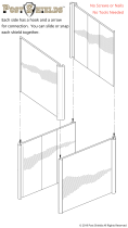
Figure 7: Connector Wiring - Cable Shield ............................................................................................................. 35
Figure 8: Wiring – RN3320-(01), CU5301, IN3300 ................................................................................................ 36
Figure 9: Wiring – RN3320-(01), CU5301, IN3300-20 ........................................................................................... 37
Figure 10: Wiring – RN3330-(01), CU5301, IN3300 .............................................................................................. 38
Figure 11: RN33XX – Potentiometer for System Adjustment ................................................................................. 40
List of Abbreviations
List of Abbreviations
AM
Amplitude Modulation
ARINC
Aeronautical Radio Incorporation
BAPT
Bundesamt für Post und Telekommunikation (since 07/2010 Bundesnetzagentur)
CU
Control Unit
DME
Distance Measuring Equipment
EEPROM
Electrical Erasable Programmable Read-only Memory
FAA
Federal Aviation Administration
FTZ
Fernmelde-Technisches Zentralamt
GS
Glideslope
ILS
Instrument Landing System (LOC, GS Signals)
LBA
Luftfahrt-Bundesamt
LOC
Localizer
NAV
Navigation
OBS
Omni Bearing Selector
RMI
Radio-Magnetic Indicator
RMU
Radio Management Unit
VCO
Voltage Controlled Oscillator
VOR
Very High Frequency Omnidirectional Radio Range

Installation and Operation
Becker Avionics
8 RN3320 / RN3330 DV60603.03 Issue 02 November 2019
Units
Units
A
Ampere
mA
Milliampere
°C
Degree Celsius
cm
Centimeter
dBm
Power Ratio in Decibel referenced to 1 mW
dB
Decibel
g
Gram
kg
Kilogram
kHz
Kilohertz
MHz
Megahertz
mm
Millimeter
Ohm (Ω)
Resistance
s
Second
V
Volt
mV
Millivolt
W
Watt
mW
Milliwatt
"
Inch
°
Angular degree
General Safety Definitions
Indicates a hazardous situation which, if not prevented, will result in death or
serious injury.
Indicates a hazardous situation which, if not prevented, could result in death or
serious injury.
Indicates a hazardous situation which, if not prevented, could result in minor or
moderate injury.
Is used to address practices not related to physical injury.
Safety instructions (or equivalent) signs indicate specified safety-related
instructions or procedures.

Becker Avionics
Installation and Operation
DV60603.03 Issue 02 November 2019 RN3320 / RN3330 9
Disposal
The packaging material is inflammable by burning, toxic fumes may develop.
This product contains materials that fall under the special disposal regulation. We recommend the
disposal of such materials in accordance with the current environmental laws.
• Dispose circuit boards by a technical waste dump which is approved to take on e.g.
electrolytic aluminium capacitors. Do under no circumstances dump the circuit boards with
normal waste dump.
Warranty Conditions
The device(s) may be installed on an aircraft only by an approved aeronautical
company (e.g. Part 145) which shall also examine the installation.
Any change made by the user excludes any liability on our part (excluding the work described in this
manual).
• The device must not be opened.
• Do not make any modifications to the device, except for those described in the manual.
• Make connections to the inputs, outputs and interfaces only in the manner described in
the manual.
• Install the devices according to the instructions.
We cannot give any guarantee for other methods.
Conditions of Utilization
With this device you bought a product which was manufactured and tested before delivery with the
utmost care.
Please take your time to read the instructions which you ought to follow closely during installation and
operation.
Otherwise all claims under the warranty will become void and a decreased service life or even
damages must be expected.
The user is responsible for protective covers and/or additional safety measures in
order to prevent damages to persons and electric accidents.
Additional Conditions of Utilization
Please refer to "Safety-Conscious Utilization", page 18.
Non-Warranty Clause
We checked the contents of this publication for compliance with the associated hard and software. We
can, however, not exclude discrepancies and do therefore not accept any liability for the exact
compliance. The information in this publication is regularly checked, necessary corrections will be part
of the subsequent publications.

Installation and Operation
Becker Avionics
10 RN3320 / RN3330 DV60603.03 Issue 02 November 2019
Blank Page

Becker Avionics
General Description
Introduction
DV60603.03 Issue 02 November 2019 RN3320 / RN3330 11
1 General Description
In this chapter you can read about:
1.1 Introduction.................................................................................................................................. 12
1.2 Purpose of Equipment ................................................................................................................. 13
1.3 Variants Overview ....................................................................................................................... 13
Software Status ................................................................................................................. 13
1.4 Associated Devices ..................................................................................................................... 13
Overview ........................................................................................................................... 14
1.5 Scope of Functionality ................................................................................................................. 15
Receiver - VOR/LOC/GS .................................................................................................. 15
Data Transfer / Data Availability ....................................................................................... 15
Communication Interface .................................................................................................. 15
Signal Interface (Indicators) .............................................................................................. 16
Additional Pointers and Flags ........................................................................................... 16
Autopilot (VOR/LOC and GS) ........................................................................................... 16
VOR/LOC and GS Super Flags ........................................................................................ 16
ILS Mode Control Function ............................................................................................... 16
Audio Output ..................................................................................................................... 16
Self-Test ............................................................................................................................ 16
Special Features ............................................................................................................... 17
1.5.11.1 Remote-Control of a DME Device ............................................................................... 17
1.6 Safety-Conscious Utilization ....................................................................................................... 18
1.7 Restriction for Use ....................................................................................................................... 18
1.8 Technical Data ............................................................................................................................ 19
General Characteristics .................................................................................................... 19
VOR/LOC Receiver ........................................................................................................... 19
GS Receiver ...................................................................................................................... 20
Dimensions & Weight........................................................................................................ 21
Software ............................................................................................................................ 21
Hardware .......................................................................................................................... 21
Continued Airworthiness ................................................................................................... 21
Environmental Condition ................................................................................................... 22
Certifications ..................................................................................................................... 23
1.9 Order Code.................................................................................................................................. 24
RN33XX - Remote-Controlled Navigation Receiver ......................................................... 24
Accessories ....................................................................................................................... 24
This manual describes the Becker Avionics remote-controlled navigation receivers RN3320-(XX) and
RN3330-(XX). The type plate on your device shows the part number for identification purposes
(see "Type Plate", page 27).
Before starting operation of the device(s) please read this manual carefully, with particular attention to
the description referring to your device(s).

General Description
Becker Avionics
Introduction
12 RN3320 / RN3330 DV60603.03 Issue 02 November 2019
1.1 Introduction
The technical information in this document applies to the described product(s) RN3320-(XX) and
RN3330-(XX).
• We also use the term RN33XX, for descriptions instead writing the complete model
number.
• If a description refers to only one of the product variants its full name is used or it is
specified accordingly.
The manuals “Maintenance and Repair” (M&R), “Installation and Operation (I&O) contain the sections:
Section
DV60603.04
M&R
DVx60603.03
I&O
General
X
X
Installation
X
X
Operation
X
X
Theory of Operation
X
N/A
Maintenance and Repair
X
N/A
Illustrated Parts List
X
N/A
Modification and Changes
X
N/A
Circuit Diagrams
X
N/A
Certifications
X
N/A
Attachments
X
N/A

Becker Avionics
General Description
Associated Devices
DV60603.03 Issue 02 November 2019 RN3320 / RN3330 13
1.2 Purpose of Equipment
• The Becker navigation receivers RN33XX are made to receive and convert VOR and LOC
signals.
o RN3320, RN3330: Reception and evaluation of VOR- and LOC-signals in the
frequency range 108...117.95 MHz on 200 channels.
RN3320 additionally: Reception and evaluation of glide path signals (GS) in the
frequency range 329.15...335.00 MHz on 40 channels.
o The receivers provide the NAV composite signal to an external VOR/LOC
converter.
• RN33XX use RS422 interfaces for communication with a control device.
1.3 Variants Overview
RN
33
XX
-
(XX)
Identifier
Model Number
01= Converter included
20= VOR/LOC + GS
02= NAV system componente only
30= VOR/LOC
obs
olete
Software Status
Descriptions see "Software/Firmware Status – Functionality", page 27.
1.4 Associated Devices
These devices can operate with RN3320/RN3330:
Device
Function
CU5301
Becker Avionics Control Unit
RMU5000
Becker Avionics Radio Management Unit
Glass cockpit
Third party product
This manual describes the operation and installation of the navigation receivers RN3320/RN3330 from
Becker Avionics. For other devices please refer to the corresponding manuals.

General Description
Becker Avionics
Associated Devices
14 RN3320 / RN3330 DV60603.03 Issue 02 November 2019
Overview
Examples: Possible equipment combinations: *designs depend on variants
Becker Avionics
Control Unit CU5301
Becker Avionics
NAV Receiver & Indicator
RN33XX & IN3300
Becker Avionics
Marker & Marker Lamps
Becker Avionics
Control Unit CU5301
Becker Avionics
NAV Receiver & Indicator
RN33XX & IN3300
Becker Avionics
NAV Converter & Third Party RMI Indicator
(optional)
Becker Avionics
Marker & Marker Lamps
Glass Cockpit
Becker Avionics
NAV Receiver
RN33XX
Becker Avionics
NAV Converter & Third Party RMI Indicator
(optional)
Becker Avionics
Marker & Marker Lamps

Becker Avionics
General Description
Scope of Functionality
DV60603.03 Issue 02 November 2019 RN3320 / RN3330 15
1.5 Scope of Functionality
The mechanical construction of RN33XX is for installation in aircraft including rotary wing aircraft.
• The RN33XX is made for installation in the avionics compartment.
• All connectors are on the front side of the device.
• Installation via mounting plate.
Figure 1: RN33XX Navigation Receiver*
*design depends on variant
The device consists of these circuit boards:
• Chassis Board.
• Processor Board.
• Interface Board.
• VOR/LOC Receiver Board.
• VOR/LOC Converter Board (depends on variant).
• GS Receiver Board (depends on variant).
Receiver - VOR/LOC/GS
The Becker navigation receivers RN33XX are made to receive and convert VOR and LOC signals.
• The RN3320, RN3330 is for reception and evaluation of VOR- and LOC-signals.
The converted signals can be read off with the connected VOR/ILS indicator.
o Frequency range: 108...117.95 MHz on 200 channels.
o Channel separation of 50 kHz.
• The RN3320 is additionally for reception and evaluation of glide path signals (GS).
The evaluated glide path signals are indicated by the GS needle of the connected
VOR/ILS indicator.
o Frequency range 329.15...335.00 MHz on 40 channels.
o Channel separation of 150 kHz.
Data Transfer / Data Availability
After power on, an initialization procedure is started between navigation receiver and control device.
Communication Interface
The navigation receiver RN33XX has a RS422 interface for communication data transmission with the
control device.

General Description
Becker Avionics
Scope of Functionality
16 RN3320 / RN3330 DV60603.03 Issue 02 November 2019
Signal Interface (Indicators)
Indicators made by other manufacturers and with standard ARINC resolver are compatible with the
VOR/LOC converter of the navigation receiver and may be used.
Additional Pointers and Flags
It is possible to connect up to two analog instruments parallel to the indicator without altering the
navigation receiver.
For example, instruments with:
• VOR/LOC pointer, VOR/LOC warning flag.
• TO/FROM indication.
• GS pointer and GS warning flag.
Autopilot (VOR/LOC and GS)
The navigation receiver has outputs for connection of an autopilot.
VOR/LOC and GS Super Flags
The converted VOR/LOC and GS signals can be feed to the super flag inputs of course guidance
systems (controlled by the super flag control outputs).
For further details please see "Aircraft Wiring" page 35.
ILS Mode Control Function
The ILS mode control function can be used to operate an Instrument Flight Control (IFC) system or
similar systems, such as automatic switching of an autopilot to VOR and ILS modes.
For further details please see "Aircraft Wiring" page 35.
Audio Output
The audio output of the navigation receiver is set to a symmetrical audio output on delivery.
• A symmetrical selection system or head set can be connected.
The audio output can also be changed to an asymmetric audio output.
For further details please see "Aircraft Wiring" page 35.
Self-Test
The self-test of the navigation receiver can be initiated by the user.
• With the TEST function through a control device a functional check will be started.
• The VOR/LOC evaluation and GS evaluation will be examined.

Becker Avionics
General Description
Scope of Functionality
DV60603.03 Issue 02 November 2019 RN3320 / RN3330 17
Special Features
1.5.11.1 Remote-Control of a DME Device
The NAV receiver is made for the connection of a remote-controlled DME device with parallel signal
transmission in 2-out-of-5 code.

General Description
Becker Avionics
Restriction for Use
18 RN3320 / RN3330 DV60603.03 Issue 02 November 2019
1.6 Safety-Conscious Utilization
The device(s) may be installed on an aircraft only by an approved aeronautical
company (e.g. Part 145) which shall also examine the installation.
• The installation of the device into an aircraft may be carried out only by
an authorized installation company. The country regulations always have
to be obeyed.
• Use the product only in the specified conditions, see "Technical Data",
page 19.
• Power supply:
o Do not connect the device to AC sources.
o Make sure that the device is connected to the mandatory DC source, see
"Technical Data", page 19.
o Do not connect the device with reversed polarity to the DC source.
• Circuit breaker:
o Use the recommended fuses in the power supply line for protection of the
application, see "Technical Data", page 19.
Cleaning:
• Do not use aggressive cleaning agents e.g. Acetone.
o These cleaning agents can cause damages.
Excessive pulses on the DC bus of the aircraft may cause damage on electrical
circuits of any installed instrument.
Do not power-on the device during engine start or shutdown.
1.7 Restriction for Use
The product is to be used inside the declared limits.

Becker Avionics
General Description
Technical Data
DV60603.03 Issue 02 November 2019 RN3320 / RN3330 19
1.8 Technical Data
General Characteristics
RN3320/RN3330
Specifications
Power supply voltage
12.4…30.1 VDC
Current consumption @27.5 V
RN3320: 340 mA
RN3330: 260 mA
Emergency supply voltage
10 VDC
Internal fuse protection
1.5 A
Recommended external fuse protection
1 A
Operating temperature
-55…+55 °C (short time +70 °C)
Storage temperature
-55…+85 °C
Max. operating altitude
50 000 ft
Interface
RS422
VOR/LOC Receiver
RN33XX
Specifications
RN3320/RN3330 - VOR/LOC Receiver Features
Receiver type
Triple-conversion superheterodyne receiver
Frequency range
108.00…117.95 MHz
Intermediate frequency
IF1: 71.05 MHz
IF2: 21.40 MHz
IF3: 455 kHz
Number of channels
200
Channel spacing
50 kHz
Selectivity
≥ 65 dB @ ΔF ≥ ± 50 kHz
Bandwidth
≥ 12 kHz @ 6 dB
Sensitivity
≤ -93 dBm for ≥ 6 dB (S+N)/N
AGC
≤ 3 dB from -87…-10 dBm
AF distortion
≤ 10%
AF rated output
150 mW into 300 Ω
Function VOICE
≥ 20 dB attenuation @ 20 Hz
NAV signal (composite)
500 mV @ 30 Hz, mod = 30%
DME remote control
parallel, with 2-out-of-5 code in accordance with
ARINC 410

General Description
Becker Avionics
Technical Data
20 RN3320 / RN3330 DV60603.03 Issue 02 November 2019
RN33XX
Specifications
RN3320/RN3330 - VOR/LOC System Features
Bearing error
Standard Conditions:
≤ ± 1° with precision resolver (ARINC 407)
Environmental Conditions (95% probability):
≤ ± 2.7° with precision resolver (ARINC 407)
Course deviation for full scale deflection
± 10°
Course deviation current
15 μA per 1° course deviation
LOC centering error
Environmental Conditions (95% probability):
≤ 11% of standard deviation
LOC standard deviation current
90 μA per 1000 Ω load
RN33XX-(01) - variants only
Resolver output
Standard value as per ARINC 407
VOR/LOC needle output
max. of 3 pointers and/or flags with 1 kΩ each
VOR/LOC warning flag output
max. of 3 pointers and/or flags with 1 kΩ each
TO/FROM output
max. of 3 pointers and/or flags with 1 kΩ each
Autopilot output
for VOR course tracking and ILS mode
GS Receiver
RN3320
Specifications
Receiver type
Single-conversion superheterodyne receiver
Frequency range
329.15…1335.00 MHz
Intermediate frequency
21.40 MHz
Number of channels
40
Channel spacing
150 kHz
Selectivity
≥ 42 dB @ ΔF ≥ ± 150 kHz
Bandwidth
≥ ± 20kHz @ 6 dB
Sensitivity
≥ -80 dBm for Flag OFF condition
Centering error
Standard Conditions:
< 5% of standard deviation
Environmental Conditions (95% probability):
< 13% of standard deviation
GS-needle output
max. of 3 needles and/or flags with 1 kΩ each
GS-warning flag output
max. of 3 needles and/or flags with 1 kΩ each
GS-autopilot output
max. of 3 needles and/or flags with 1 kΩ each
/