Page is loading ...

MN-964 • (021908) • ECR 9350
For maximum effectiveness and safety,
please read these instructions completely
before proceeding with installation.
Failure to read these instructions can result in an
incorrect installation.
INSTALLATION GUIDE
Kit 57213
Ford Transit
(Single Rear Wheel)
2-Wheel Drive


TABLE OF CONTENTS
Installation Diagram .......................................2
Hardware List ........................................................3
Tools List ............................................................3
Introduction ..............................................4
Important Safety Notice ................................................4
Notation Explanation ................................................... 4
Installing the LoadLifter 5000 System ........................5
Getting Started .......................................................5
Assembling the Air Springs ..............................................7
Installing the Air Spring Assemblies ....................................... 9
ABS Line Adjustment on Driver’s (Left) Side .................................11
Installing the Air Lines ............................. 12
Installing the Heat Shield ................................................13
Photos of Finished Assemblies ...........................................14
Before Operating ........................................ 15
Installation Checklist ...................................................15
Maintenance and Use Guidelines .......................... 15
Minimum and Maximum Pressure .........................................15
Warranty and Return Policy ............................... 15

MN-964
2
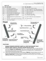
Installation Diagram
g. 1
The P-clamp shown here
is in the passenger’s (right)
side position on the upper
bracket.
LoadLifter 5000

MN-964
3
HARDWARE LIST
Hardware and Tools Lists
Item Part # Description................................Qty
A 01531 Clamp bar ...........................................2
B 07954 Frame bracket ..................................... 2
C 07956 Air spring bracket................................2
D 03906 Lower bracket .....................................2
E 58437 Air spring ............................................. 2
F 11951 Roll plate .............................................4
G 21848 90 degree swivel fitting .......................2
H 17215 3/8”-24 x 7/8” flat-head screw ...........4
I 17203 3/8”-24 x 7/8” hex cap screw .............4
J 18427 3/8” lock washer .................................4
K 18444 3/8” flat washer ..................................12
L 10778 P clamp ...............................................2
Item Part # Description................................Qty
M 17133 3/8”-16 x 6” Carriage bolt ................... 4
N 17361 3/8”-16 x 1 1/4” Carriage bolt ............4
O 17366 M10-150 x 35 Button-head screw ......2
P 18435 3/8” Nylon lock nut .............................8
AA* 20086 Air line assembly .................................1
BB* 10466 Zip tie ..................................................6
CC* 21230 Valve cap.............................................2
DD* 18501 5/16” flat washer ................................. 2
EE* 21234 Rubber washer....................................2
FF* 18401 Star washer .........................................2
GG* 21233 5/16” hex nut ......................................4
*Not shown in fig. 1.
Missing or damaged parts? Call Air Lift customer
service at (800) 248-0892 for a replacement part.
STOP!
TOOLS LIST
Description .............................................. Qty
Hoist or floor jacks ............................................... 1
Safety stands ........................................................ 2
Safety glasses ...................................................... 1
Torque wrench ...................................................... 1
Standard open-end combo wrenches..............SET
Medium size adjustable wrench ........................... 1
Ratchet ................................................................. 1
Metric and standard sockets ............................SET
Description .............................................. Qty
6mm hex wrench (socket if available) .................. 1
7/32” hex wrench (socket if available) .................. 1
5/16” drill bit (very sharp) ..................................... 1
Heavy duty drill ..................................................... 1
Hose cutter, razor blade, or sharp knife ............... 1
Air compressor or compressed air source ........... 1
Spray bottle with dish soap/water solution .......... 1
LoadLifter 5000

MN-964
4
Introduction
The purpose of this publication is to assist with the installation and maintenance of the
LoadLifter 5000 series air spring kits. All LoadLifter 5000 series kits utilize sturdy, reinforced,
commercial-grade single or double, depending on the kit, convolute bellows.
The air springs are manufactured like a tire with layers of rubber and cords that control
growth. LoadLifter 5000 kits provide up to 5,000 pounds (2,268kg) of load-leveling support
with air adjustability from 5-100 PSI (.34-7BAR).
It is important to read and understand the entire installation guide before beginning
installation or performing any maintenance, service or repair.
IMPORTANT SAFETY NOTICE
The installation of this kit does not alter the gross vehicle weight rating (GVWR) or
payload of the vehicle. Check your vehicle’s owner’s manual and do not exceed the
maximum load listed for your vehicle.
Gross vehicle weight rating: The maximum allowable weight of the fully loaded vehicle
(including passengers and cargo). This number — along with other weight limits, as
well as tire, rim size and inflation pressure data — is shown on the vehicle’s Safety
Compliance Certification Label.
Payload: The combined, maximum allowable weight of cargo and passengers that the
truck is designed to carry. Payload is GVWR minus the base curb weight.
NOTATION EXPLANATION
Hazard notations appear in various locations in this publication. Information which is
highlighted by one of these notations must be observed to help minimize risk of personal
injury or possible improper installation which may render the vehicle unsafe. Notes are
used to help emphasize areas of procedural importance and provide helpful suggestions.
The following definitions explain the use of these notations as they appear throughout
this guide.
INDICATES IMMEDIATE HAZARDS WHICH WILL RESULT IN SEVERE PERSONAL
INJURY OR DEATH.
INDICATES HAZARDS OR UNSAFE PRACTICES WHICH COULD RESULT IN SEVERE
PERSONAL INJURY OR DEATH.
INDICATES HAZARDS OR UNSAFE PRACTICES WHICH COULD RESULT IN DAMAGE
TO THE MACHINE OR MINOR PERSONAL INJURY.
Indicates a procedure, practice or hint which is important to highlight.
NOTE
DANGER
WARNING
CAUTION
LoadLifter 5000

MN-964
5
GETTING STARTED
COMPRESSED AIR CAN CAUSE INJURY AND DAMAGE TO THE VEHICLE AND PARTS
IF IT IS NOT HANDLED PROPERLY. FOR YOUR SAFETY, DO NOT TRY TO INFLATE THE
AIR SPRINGS UNTIL THEY HAVE BEEN PROPERLY SECURED TO THE VEHICLE.
1. Raise the vehicle and support it, using safety stands or equivalent, so that the axle
can be safely dropped away from the frame (Fig. 2). This will need to be done in
order for the air spring assembly to be positioned between the axle and frame.
2. Unbolt and remove the stock jounce bumpers from under the frame rails on both
sides (Figs. 3 & 4). This is a necessary step to install the kit.
DANGER
g. 2
g. 3
g. 4
Driver’s (left)
side shown
with jounce
bumper
removed.
LoadLifter 5000
Installing the LoadLifter 5000 System

MN-964
6
3. Insert two 3/8”-16 x 1 1/4” carriage bolts (N) through the frame bracket (B). The
heads of the bolts should be on the flange side of the bracket (Fig. 5).
4. Install the upper frame bracket assembly onto the frame using the M10-150 x 35
button head screw (O) making sure the flange on the bracket is on the inside of the
frame rail and pointing up (Figs. 6 & 7). Push the flange on the bracket up against
the frame and torque screw to 30 lb.-ft. (41Nm)
g. 5
g. 6
g. 7
N
B
Flange
O
Flange
O
Flange
Driver’s
(left) side
shown.
Passenger’s
(right) side
shown.
LoadLifter 5000

MN-964
7
ASSEMBLING THE AIR SPRINGS
1. Set a roll plate (F) over the top of the air spring (E) (Fig. 8).
The radius (rounded) edge of the roll plate (F) will be towards the air spring, so that the
air spring is seated inside both roll plates.
2. Install the 90 degrees swivel fitting (G) into the top of the air spring, finger-tight plus
1 1/2 turns.
3. Set the air spring bracket (C) over the air spring and roll plate and attach with the
3/8”-24 x 7/8” flat-head screws (H) (Fig. 9). Torque to no more than 20 lb.-ft. (27Nm).
Repeat for the other air spring.
NOTE
g. 8
g. 9
E
C
H
F
G
LoadLifter 5000

MN-964
8
4. Insert two 3/8”-13 x 6” carriage bolts (M) through the lower bracket (Fig. 10).
Assemble the lower bracket onto the air spring assembly so the carriage bolts are
on the opposite side of the fittings (Fig. 11). Leave them loose at this time. Attach
the lower bracket to the air spring assembly with two 3/8”-24 x 7/8” hex cap screws
(I), two 3/8” lock washers (J) and two 3/8” flat washers (K) (Fig. 12). Leave them
loose at this time.
g. 10
g. 11
g. 12
Attach
the lower
brackets so
the carriage
bolts are
opposite of
the fitting on
the air spring
assembly.
I
J
K
M
LoadLifter 5000

MN-964
9
INSTALLING THE AIR SPRING ASSEMBLIES
1. If not already done, lower the axle enough for clearance to install the assemblies into
position.
2. Set the driver’s (left) and passenger’s (right) side assemblies into position making
sure that the long carriage bolt in the rear of the lower bracket, fits between the
brake/ABS lines and the axle (Fig. 13).
The lower bracket will be nested over the jounce bumper strike plate.
3. Raise the axle or lower the body of the vehicle making sure that the carriage bolts
—previously installed in the frame bracket — nests into the holes of the air spring
bracket (Fig. 14). On the back carriage bolts only, it will be necessary to install the P
clamps (L) on both sides of the assemblies (the driver’s [left] and passenger’s [right]).
Cap all the carriage bolts with 3/8” flat washers (K) and a 3/8” nylon lock nut (P).
Leave them loose at this time.
Driver’s (left) side
shown: set one
of the assemblies
into position
making sure that
the carriage bolt
goes in between
the brake/ABS
lines and the axle
as shown.
NOTE
g. 13
g. 14
K
L
P
LoadLifter 5000

MN-964
10
4. Set the axle clamp bar (A) over the long carriage bolts onto the lower bracket, under
the axle and cap with two 3/8” flat washers (K) and a 3/8” nylon lock nut (P) (Fig. 15).
Leave loose at this time.
5. The air spring bracket is slotted so it can be adjusted forward or rearward. Move the
air spring assembly so that the air spring is parallel to the upper and lower bracket.
Torque the upper hardware to 15 lb.-ft. (20Nm).
6. Once the lower bracket (D) is parallel to the upper bracket, the axle clamp bar (A) on
the lower bracket can be torqued evenly to 10 lb.-ft. (14Nm) (Fig. 16).
It may be necessary to pull the brake line away from the carriage bolt slightly on the right
hand side to gain clearance so the line will not rub on the bolt.
7. Once the upper and lower brackets are tight, it will be necessary to tighten the lower
air spring mounting hardware on the lower brackets. Slide the air spring along the
slots of the lower bracket for the final alignment of the air spring and torque the lower
mounting hardware to no more than 20 lb.-ft. (27Nm) (Fig. 17).
g. 15
g. 16
g. 17
A
K
P
NOTE
A
D
I
J
K
LoadLifter 5000

MN-964
11
ABS LINE ADJUSTMENT ON DRIVER’S (LEFT) SIDE
1. On the driver’s (left) side behind the axle, the ABS line will need to be adjusted so
that it will not rub on the lower bracket (Fig. 18).
2. To do this just pull the line out of the holder on the axle and rotate it 180 degrees,
then push it back into the holder (Fig. 19). This will change the position of the line so
that it will not come in contact with the lower bracket.
g. 18
g. 19
The ABS
line on the
driver’s
(left) side
will need
to be
moved so
that it does
not rub on
the lower
bracket.
ABS line holder
Dead space between
line and lower bracket
LoadLifter 5000

Installing the Air Lines
Choose the locations for
the Schrader valves and
drill a 5/16” (8mm) hole, if
necessary (Fig. 20).
1. Cut the air line in half.
Make clean, square cuts
with a razor blade or
hose cutter (Fig. 21). Do
not use scissors or wire
cutters.
KEEP AT LEAST 6” (152MM)
OF CLEARANCE BETWEEN
ALL AIR LINES AND THE
EXHAUST SYSTEM. AVOID
SHARP BENDS AND EDGES.
2. Use zip ties to secure
the air line to fixed points
along the chassis. Do not
pinch or kink the air line.
Leave at least 2” (51mm)
of slack in the air line to
allow for any movement
that might pull on the air
line. The minimum bend
radius for the air line is
1
”
(25mm) (Fig. 23 & 24).
3. Install the Schrader valve
in the chosen location
(Fig. 22).
g. 21
g. 20
g. 22
Hex nuts
Flat washer
Star washer
Rubber washer
Schrader
valve
Vehicle
body or
bumper
Nylon air line
to air spring
5/16” (8mm) hole
Good cut
Bad cut
CAUTION
MN-964
12
g. 23 g. 24
Tie off air line so as not to come
in contact with HVAC lined if so
equipped.
A. Inside fuel tank filler door C. License plate or
B. Inside rear wheel wells rear bumper area
MICHIGAN
XXX-XXX
www.MICHIGAN.gov
A. B. C.
LoadLifter 5000

1/2” (13mm)
dead air space
between shield
and exhaust
MN-964
13
Air line
thermal sleeve
g. 25
Exhaust
resonator
Bend
tabs
Double hose
clamps if
necessary
INSTALLING THE HEAT SHIELD
1. Attach the metal heat shield to the exhaust where it is closest to the passenger's
(right) side air spring. Slide the air line thermal sleeve over the air line and position it
where the air line is closest to the exhaust. (Fig. 25).
LoadLifter 5000

MN-964
14
PHOTOS OF FINISHED ASSEMBLIES
1. Safely remove the safety stands by lowering or raising the vehicle.
2. Figure 26 shows the rear view of the driver’s (left) side completed installation.
3. Figure 27 shows the rear view of the passenger’s (right) side completed installation.
g. 26
g. 27
LoadLifter 5000

CAUTION
CAUTION
MN-964
15
1. Check air pressure weekly.
2. Always maintain normal ride height. Never inflate beyond 100 PSI (7BAR).
3. If the system develops an air leak, use a soapy water solution to check all air line
connections and the inflation valve core before deflating and removing the air spring.
FOR SAFETY AND TO PREVENT POSSIBLE DAMAGE TO THE VEHICLE, DO NOT EXCEED
MAXIMUM GROSS VEHICLE WEIGHT RATING (GVWR) OR PAYLOAD RATING, AS INDICAT-
ED BY THE VEHICLE MANUFACTURER.
ALTHOUGH THE AIR SPRINGS ARE RATED AT A MAXIMUM INFLATION PRESSURE OF
100 PSI (7BAR), THE AIR PRESSURE ACTUALLY NEEDED IS DEPENDENT ON LOAD AND
GROSS VEHICLE WEIGHT RATING.
Maximum Air PressureMinimum Recommended Pressure
100 PSI (7BAR)5 PSI (.34BAR)
Maintenance and Use Guidelines
Limited Warranty and Return Policy
Air Lift Company provides a limited lifetime warranty to the original purchaser of its load support
products, that the products will be free from defects in workmanship and materials when used
on cars and trucks as specified by Air Lift Company and under normal operating conditions,
subject to the requirements and exclusions set forth in the full Limited Warranty and Return
Policy that is available at www.airliftcompany.com/warranty.
For additional warranty information contact Air Lift Company customer service.
Air Lift Company reserves the right to make changes and improvements to its products
and publications at any time. For the latest version of this manual, contact Air Lift
Company at (800) 248-0892 or visit our website at www.airliftcompany.com.
Clearance test — Inflate the air springs to 40-60 PSI (2.8-4.1BAR) and make sure
there is at least 1/2” (13mm) clearance from anything that might rub against each
sleeve. Be sure to check the tire, brakes, frame, shock absorbers and brake cables.
Leak test before road test — Inflate the air springs to 40-60 PSI (2.8-4.1BAR) and
check all connections for leaks. All leaks must be eliminated before the vehicle is
road tested.
Heat test — Be sure there is sufficient clearance from heat sources, at least 6” (152mm)
for air springs and air lines. If a heat shield was included in the kit, install it. If there is no
heat shield, but one is required, call Air Lift customer service at (800) 248-0892.
Fastener test — Recheck all bolts for proper torque.
Road test — The vehicle should be road tested after the preceding tests. Inflate the
air springs to recommended driving pressures. Drive the vehicle 10 miles (16km) and
recheck for clearance, loose fasteners and air leaks.
Operating instructions — If professionally installed, the installer should review the
operating instructions with the owner. Be sure to provide the owner with all of the
paperwork that came with the kit.
INSTALLATION CHECKLIST
Before Operating
LoadLifter 5000

Notes
MN-964
16
LoadLifter 5000


Need Help?
Contact Air Lift Company customer service department by
calling (800) 248-0892.
For calls from outside the USA or Canada,
dial (517) 322-2144.
Need Help?
Contact Air Lift Company customer service
department by calling (800) 248-0892.
For calls from outside the USA or Canada,
dial (517) 322-2144.
Air Lift Company • 2727 Snow Road • Lansing, MI 48917 or P.O. Box 80167 • Lansing, MI 48908-0167
Toll Free (800) 248-0892 • Local (517) 322-2144 • Fax (517) 322-0240 • www.airliftcompany.com
Thank you for purchasing Air Lift products — the professional installer’s choice!
Printed in the USA
JJC-0819
California: WARNING: Cancer and Reproductive Harm – www.P65Warnings.ca.gov
1/20