Miller INFINITY WELDING HELMET - CAT Owner's manual
- Category
- Welding System
- Type
- Owner's manual
This manual is also suitable for

®
Cat
Auto-Darkening Helmets
Model: Infinity Series w/Infotrackt
OM-280510C
2019-12
To help us serve you better, go to www.MillerWelds.Com/Register

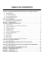
TABLE OF CONTENTS
SECTION 1 − WELDING HELMET SAFETY PRECAUTIONS − READ BEFORE USING 1.....
1-1. Symbol Usage 1............................................................
1-2. Arc Welding Hazards 1.......................................................
1-3. Proposition 65 Warnings 2....................................................
1-4. Lens Shade Selection Table 3.................................................
1-5. Principal Safety Standards 3..................................................
SECTION 2 − DEFINITIONS 4........................................................
2-1. Additional Safety Symbols And Definitions 4.....................................
2-2. Miscellaneous Symbols And Definitions 4.......................................
SECTION 3 − SPECIFICATIONS 4.....................................................
SECTION 4 − OPERATING INSTRUCTIONS 6..........................................
4-1. Helmet Controls 6...........................................................
4-2. Auto On/Off Button And Grind Mode/Low Battery Light 7...........................
4-3. Mode Control Button 8.......................................................
4-4. Variable Shade Control 9.....................................................
4-5. Lens Delay Control 10.........................................................
4-6. Sensitivity Control 11..........................................................
4-7. Typical Lens Adjustment Procedure 12...........................................
4-8. Information Control Button 13...................................................
4-9. Arc Time Control 14...........................................................
4-10. Clock Control 15.............................................................
4-11. Timer Control 16.............................................................
4-12. Alarm Control 17.............................................................
4-13. Setting Help Menu Language And Viewing Help Menu 18...........................
SECTION 5 − ADJUSTING HEADGEAR 19.............................................
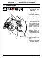
5-1. Adjusting Headgear 19........................................................
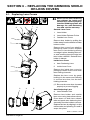
SECTION 6 − REPLACING THE GRINDING SHIELD OR LENS COVERS 20................
6-1. Replacing Lens Covers 20.....................................................
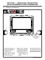
SECTION 7 − REPLACING THE BATTERY (AUTO-DARKENING LENS ASSEMBLIES) 21....
7-1. Replacing The Batteries 21.....................................................
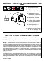
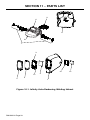
SECTION 8 − INSTALLING OPTIONAL MAGNIFYING LENS 22...........................
SECTION 9 − MAINTENANCE AND STORAGE 22......................................
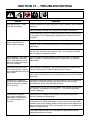
SECTION 10 − TROUBLESHOOTING 23...............................................
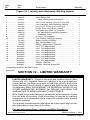
SECTION 11 − PARTS LIST 24........................................................
SECTION 12 − LIMITED WARRANTY 25...............................................

OM-280510 Page 1
SECTION 1 − WELDING HELMET SAFETY PRECAUTIONS −
READ BEFORE USING
helmet 2018-08
Protect yourself and others from injury — read, follow, and save these important safety
precautions and operating instructions.
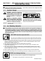
1-1. Symbol Usage
This group of symbols means Warning! Watch
Out! ELECTRIC SHOCK, MOVING PARTS,
and HOT PARTS hazards. Consult symbols
and related instructions below for necessary
actions to avoid the hazards.
Indicates special instructions.
DANGER! − Indicates a hazardous
situation which, if not avoided, will
result in death or serious injury. The
possible hazards are shown in the
adjoining symbols or explained in
the text.
Indicates a hazardous situation
which, if not avoided, could result in
death or serious injury. The possible
hazards are shown in the adjoining
symbols or explained in the text.
NOTICE − Indicates statements not related to
personal injury.
1-2. Arc Welding Hazards
Only qualified persons should install, operate, maintain, and repair this equipment. A
qualified person is defined as one who, by possession of a recognized degree, certificate,
or professional standing, or who by extensive knowledge, training and experience, has
successfully
demonstrated ability to solve or resolve problems relating to the subject
matter, the work, or the project and has received safety training to recognize and avoid
the hazards involved.
Arc rays from the welding process produce intense visible and invisible (ultravio-
let and infrared) rays that can burn eyes and skin. Sparks fly off from the weld.
Wear a welding helmet fitted with a proper shade of filter to protect your face and eyes when
welding or watching (see ANSI Z49.1 and Z87.1 listed in Safety Standards). Refer to Lens
Shade Selection table in Section 1-4.
Wear approved safety glasses with side shields under your helmet.
Use protective screens or barriers to protect others from flash, glare, and sparks; warn
others not to watch the arc.
Wear body protection made from durable, flame−resistant material (leather, heavy cotton,
wool). Body protection includes oil-free clothing such as leather gloves, heavy shirt, cuffless
trousers, high shoes, and a cap.
• Before welding, adjust the auto-darkening lens sensitivity setting to meet the application.
• Stop welding immediately if the auto-darkening lens does not darken when the arc is struck.
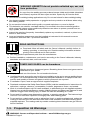
ARC RAYS can burn eyes and skin.
NOISE can damage hearing.
Noise from some processes or equipment can damage hearing.
Wear approved ear protection if noise level is high.

OM-280510 Page 2
WELDING HELMETS do not provide unlimited eye, ear, and
face protection.
Arc rays from the welding process produce intense visible and invisible (ultraviolet
and infrared) rays that can burn eyes and skin. Sparks fly off from the weld.
Use helmet for welding/cutting applications only. Do not use helmet for laser welding/cutting.
Use impact resistant safety spectacles or goggles and ear protection at all times when using
this welding helmet.
Do not use this helmet while working with or around explosives or corrosive liquids.
This helmet is not rated for overhead welding. Do not weld in the direct overhead position
while using this helmet unless additional precautions are taken to protect yourself from arc
rays, spatter, and other hazards.
Inspect the auto-lens frequently. Immediately replace any scratched, cracked, or pitted cover
lenses or auto-lenses.
Lens and retention components must be installed as instructed in this manual to ensure
compliance with ANSI Z87.1 protection standards.
READ INSTRUCTIONS.
Read and follow all labels and the Owner’s Manual carefully before in-
stalling, operating, or servicing unit. Read the safety information at the be-
ginning of the manual and in each section.
Use only genuine replacement parts from the manufacturer.
Perform installation, maintenance, and service according to the Owner’s Manuals, industry
standards, and national, state, and local codes.
FUMES AND GASES can be hazardous.
Welding produces fumes and gases. Breathing these fumes and gases can be
hazardous to your health.
Keep your head out of the fumes. Do not breathe the fumes.
Ventilate the work area and/or use local forced ventilation at the arc to remove welding fumes
and gases. The recommended way to determine adequate ventilation is to sample for the com-
position and quantity of fumes and gases to which personnel are exposed.
If ventilation is poor, wear an approved air-supplied respirator.
Read and understand the Safety Data Sheets (SDSs) and the manufacturer’s instructions for
adhesives, coatings, cleaners, consumables, coolants, degreasers, fluxes, and metals.
Work in a confined space only if it is well ventilated, or while wearing an air-supplied respirator.
Always have a trained watchperson nearby. Welding fumes and gases can displace air and
lower the oxygen level causing injury or death. Be sure the breathing air is safe.
Do not weld in locations near degreasing, cleaning, or spraying operations. The heat and rays
of the arc can react with vapors to form highly toxic and irritating gases.
Do not weld on coated metals, such as galvanized, lead, or cadmium plated steel, unless the
coating is removed from the weld area, the area is well ventilated, and while wearing an air-
supplied respirator. The coatings and any metals containing these elements can give off toxic
fumes if welded.
1-3. Proposition 65 Warnings
WARNING: Cancer and Reproductive Harm − www.P65W
arnings.ca.gov

OM-280510 Page 3
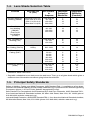
1-4. Lens Shade Selection Table
Process
Electrode Size
in. (mm)
Arc Current
in
Amperes
Minimum
Protective
Shade No.
Suggested
Shade No.
(Comfort)*
Shielded Metal Arc
Welding (SMAW)
Less than 3/32 (2.4)
3/32−5/32 (2.4−4.0)
5/32−1/4 (4.0−6.4)
More than 1/4 (6.4)
Less than 60
60−160
160−250
250−550
7
8
10
11
−−
10
12
14
Gas Metal
Arc Welding
(GMAW)
Flux Cored
Arc Welding
(FCAW)
Less than 60
60−160
160−250
250−500
7
10
10
10
−−
11
12
14
Gas Tungsten Arc
Welding (TIG)
Less than 50
50−150
150−500
8
8
10
10
12
14
Air Carbon
Arc Cutting (CAC-A)
Light
Heavy
Less than 500
500−1000
10
11
12
14
Plasma Arc
Cutting (PAC)
Less than 20
20−40
40−60
60−80
80−300
300−400
400−800
4
5
6
8
8
9
10
4
5
6
8
9
12
14
Plasma Arc Welding
(PAW)
Less than 20
20−100
100−400
400−800
6
8
10
11
6−8
10
12
14
Reference: ANSI Z49.1:2012
* Start with a shade that is too dark to see the weld zone. Then, go to a lighter shade which gives a
sufficient view of the weld zone without going below the minimum.
1-5. Principal Safety Standards
Safety in Welding, Cutting, and Allied Processes, ANSI Standard Z49.1, is available as a free down-
load from the American Welding Society at http://www.aws.org or purchased from Global Engineering
Documents (phone: 1-877-413-5184, website: www
.global.ihs.com).
Safe Practice For Occupational And Educational Eye And Face Protection, ANSI Standard Z87.1,
from American National Standards Institute, 25 West 43rd Street, New York, NY 10036 (phone:
212-642-4900, website: www.ansi.org).
Industrial Head Protection, ANSI/ISEA Standard Z89.1, from American National Standards Institute,
25 West 43rd Street, New York, NY 10036 (phone: 212-642-4900, website: www.ansi.org).

OM-280510 Page 4
SECTION 2 − DEFINITIONS
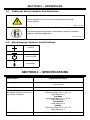
2-1. Additional Safety Symbols And Definitions
Warning! Watch Out! There are possible hazards as shown
by the symbols.
Safe1 2012−05
Safe125 2019−11
Accidental ingestion prevention. Keep battery away from children.
Battery is harmful if swallowed.
2-2. Miscellaneous Symbols And Definitions
Positive
Negative
Power On/Off
Information
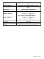
SECTION 3 − SPECIFICATIONS
Specification Digital Infinity Helmet
Viewing Field 4.4 x 3.1 in
(112 x 78 mm)
Reaction Time 0.0000500 sec (1/20,000)
Available Shades
All Shades Provide Continuous
UV And IR Protection.
Weld Mode
Darkened State: No. 8 − No. 13
Light State: No. 3
Cut Mode
Darkened State: No. 5 − No. 8
Light State: No. 3
Grind Mode
Light State: No. 3
X-Mode
Darkened State: No. 8 − No. 13
Light State: No. 3
Sensitivity Control Adjustable For Varying Ambient Light And Welding Arc

OM-280510 Page 5
Delay Control
Slows Lens Dark-To-Light State Between 0.1 And 1.0
Seconds
Automatic Power Off Shuts Lens Off 45 Minutes After Last Arc Is Struck
Low Battery Light Red Led Illuminates To Indicate 2−3 Days Remaining Battery
Life
Power Supply Panasonic CR2450 Lithium Batteries
(Miller Part No. 217043)
Sensors Independent/Redundant (Four)
Operating T
emperature
14F to 131F / −10C to +55C
When Stored In Extremely Cold Temperatures, Warm Hel-
met To Ambient Temperature Before Welding.
Storage T
emperature
−4F to 158F / −20C to +70C
When Stored In Extremely Cold Temperatures, Warm Hel-
met To Ambient Temperature Before Welding.
Total Weight 23 oz (650 g)
Standards Meets ANSI Z87.1+ And CSA Z94.3 Standards
Warranty Three Years From Date Of Purchase (Section 12)

OM-280510 Page 6
SECTION 4 − OPERATING INSTRUCTIONS
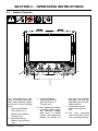
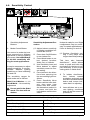
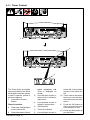
4-1. Helmet Controls
The auto-darkening lens
turns on (darkens) automati-
cally when welding begins
and turns off when welding
stops.
1 Auto On/Off Button
(See Section 4-2)
Mode Control Button
(Section 4-3)
2 Grind Mode/Low
Battery Light (Section
4-2)
3
Lens/Information
Adjustment Buttons
(See Sections 4-4
Through 4-6)
Use adjustment buttons
to change shade, delay,
and sensitivity settings
when lens is in Mode
function. Use adjustment
buttons to change arc
time, clock, timer, alarm,
language, and help set-
tings when lens is in Infor-
mation function.
4 Information Control
Button (See Section
4-8)
The lens assembly
saves the shade, sensi-
tivity, and delay settings.
1
3
4
2

OM-280510 Page 7
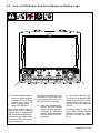
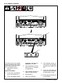
4-2. Auto On/Off Button And Grind Mode/Low Battery Light
The auto-darkening lens
turns on (darkens) auto-
matically when welding
begins and turns off
when welding stops.
1 Auto On/Off Button
Press Auto On/Off button to
check if the lens is working
properly and to begin Mode
and Information adjustments.
When the Auto On/Off button
is pressed, the LCD control
panel will turn On.
Press and hold the Auto On/
Off button to turn the LCD
control panel Off. Lens is on
and will function properly.
After four minutes of in-
activity, the LCD control
panel will turn off auto-
matically to conserve
power. Press any button
to wake up the LCD con-
trol panel.
2 Grind/Low Battery Light
The Grind/Low Battery light
blinks when the lens is in the
Grind mode. Light stays on
when 2−3 days of battery life
remain.
If battery power is low, re-
place with CR2450 lithium
batteries (2 required − Miller
Part No. 217043). See Sec-
tion 7.
1
2

OM-280510 Page 8
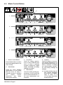
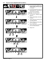
4-3. Mode Control Button
1 Mode Control Button
Press Mode button to select
the mode appropriate for the
work activity.
2 Weld Mode
Used for most welding
applications. In this mode
the lens turns on when it
optically senses a welding
arc. Adjust shade,
sensitivity, and delay
settings as needed.
3 Cut Mode
Used for cutting applica-
tions. In this mode the lens
turns on when it optically
senses a cutting arc. Adjust
shade, sensitivity, and delay
settings as needed.
4 Grind Mode
Used for metal grinding ap-
plications. In this mode the
lens is fixed at shade No. 3.
No lens adjustments are
possible.
5 X-Mode
Used for outdoor or low cur-
rent welding applications. In
this mode the lens turns on
when it senses a welding
arc. Adjust shade, sensitiv-
ity, and delay settings as
needed.
Nearby welding may af-
fect helmet operation
when lens is in X-Mode.
Stay at least 12 ft
(3.7 m) away from other
welding activity.
1
2
3
4
5

OM-280510 Page 9
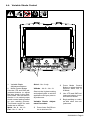
4-4. Variable Shade Control
1 Variable Shade
Adjustment Buttons
2 Mode Control Button
Use the LTR and DKR ad-
justment buttons to adjust
the lens shade in the dark-
ened state. Use the table in
Section 1-4 to select proper
shade control setting based
on your welding process.
The shade ranges for each
mode are as follows:
Weld − No. 8 − No. 13
Cut − No. 5 − No. 8
Grind − No. 3 only
X Mode − No. 8 − No. 13
Start at the highest setting
and adjust lighter to suit the
application
and your person-
al preference.
Variable Shade Adjust-
ment Procedure
Press Auto On/Off but-
ton to turn lens On.
Press Mode Control
Button to select desired
function: Weld, Cut, or
X-Mode.
Use LTR and DKR ad-
justment buttons to se-
lect desired shade.
Begin welding or contin-
ue with other lens ad-
justments.
1
2

OM-280510 Page 10
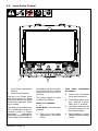
4-5. Lens Delay Control
1
1 Lens Delay Adjustment
Buttons
2 Mode Control Button
Use the Lens Delay Short
and Long buttons to adjust
the time for the lens to switch
to the clear state after weld-
ing or cutting.
The delay is particularly use-
ful in eliminating bright af-
ter-rays present in higher
amperage applications
where the molten puddle re-
mains bright momentarily af-
ter welding. Use the Lens De-
lay Control buttons to adjust
delay from 0 to 10 (0.1 to 1.0
second).
The delay ranges for each
mode are as follows:
Weld, Cut, X-Modes −
0 − 10
Grind Mode − No delay ad-
justment
There is no lens delay
adjustment in the Grind
mode.
Lens Delay Adjustment
Procedure
Press Auto On/Off but-
ton to turn helmet On.
Press Mode button to se-
lect desired function:
Weld, Cut, or X-Mode.
Use Short and Long ad-
justment buttons to se-
lect desired delay.
Begin welding or contin-
ue with other lens adjust-
ments.
2

OM-280510 Page 11
4-6. Sensitivity Control
1 Sensitivity Adjustment
Buttons
2 Mode Control Button
Use control to make the lens
more responsive to different
light levels in various welding
processes. Use a Mid-Range
or 30−50% sensitivity set-
ting for most
applications.
It may be necessary to adjust
helmet sensitivity to accom-
modate different lighting
conditions or if lens is flashing
On and Off.
The sensitivity ranges for
each mode are as follows:
Weld, Cut, X-Modes − 0 − 10
Grind Mode − No sensitivity
adjustment
! Do not weld in the Grind
mode. The lens will not
darken.
Sensitivity Adjustment Pro-
cedure
Adjust helmet sensitivity
in lighting conditions hel-
met will be used in.
Press Auto On/Off button
to turn helmet On.
Press Mode button to se-
lect desired function:
Weld, Cut, or X-Mode.
Use Sensitivity Less and
More buttons to adjust
sensitivity control to low-
est setting.
Face helmet in the direc-
tion of use, exposing it to
the surrounding light con-
ditions.
Press Sensitivity More
button until the lens dark-
ens, then press Less
button until lens clears.
An alternative method is
to press and hold the
Less button until the lens
clears.
Helmet is ready for use. Slight
readjustment
may be neces-
sary for certain applications or
if lens is flashing on and off.
Reduce Sensitivity set-
ting if lens stays dark
longer than Delay setting.
This lens also features
AutoSense, which allows
users to push and hold only
one button for the lens to ad-
just sensitivity to the proper
setting while in Weld mode.
To initiate AutoSense,
face helmet toward
workpiece and push and
hold the Less/AutoSense
button until screen indi-
cates that it is adjusting.
Lens will then set to cur-
rent lighting conditions
and can be fine tuned for
preference.
1
2
Recommended Sensitivity Settings
Stick Electrode Mid-Range
Short Circuiting (MIG) Low/Mid-Range
Pulsed & Spray (MIG) Mid-Range
Gas Tungsten Arc (TIG) Mid/High-Range
Plasma Arc Cutting/Welding Low/Mid-Range

OM-280510 Page 12
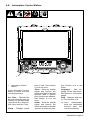
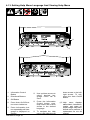
4-7. Typical Lens Adjustment Procedure
Lens assembly displays prior
settings when turned On. Re-
tained settings are not shown
in example.
In the Grind mode the lens is a
fixed shade No. 3. No lens ad-
justments are possible.
Adjusting Lens Assembly:
Turn lens On. Display screen
appears.
Select mode (Weld, Cut, Grind,
X-Mode).
Select shade by pressing LTR
and DKR buttons.
Select Delay by pressing Short
and Long buttons.
Select Sensitivity by pressing
Less and More Buttons.
Begin work.

OM-280510 Page 13
4-8. Information Control Button
1
Information
Control
Button
Press Information Control
button to select from the
following functions:
Arc Time − Records the
amount of time the lens as-
sembly is in the dark state
(exposed to arc). See Sec-
tion 4-9 to reset Arc Time.
Clock − Displays actual
time of day. See Section
4-10 to set clock.
Timer − Emits an audible
signal and flashes the
Grind mode light to alert the
operator after a specific
period of time has elapsed.
See Section 4-11 to set
timer.
Alarm − Emits an audible
signal and flashes the
Grind mode light to alert the
operator at a specific time.
See Section 4-12 to set
alarm.
Language − Sets lan-
guage for the Help menu.
See Section 4-13 to set lan-
guage.
Help − Displays Help top-
ics. See Section 4-13.
Lens automatically
exits the Information
function after one
minute of inactivity.
1

OM-280510 Page 14
4-9. Arc Time Control
The arc time function re-
cords the amount of time the
lens assembly is dark (ex-
posed to an arc).
1 Information Control
Button
2 OK Button
3 Auto On/Off Button
Arc Time Procedure
Press Auto On/Off but-
ton to turn helmet On.
Press Information
Control button
repeatedly until Arc
Time is displayed on
screen.
Press OK button to
clear the arc time to
zero.
Press Auto On/Off but-
ton when finished.
Arc time is accumulat-
ed by the second, but
only hours and minutes
are displayed.
1
2
3

OM-280510 Page 15
4-10. Clock Control
1
The clock displays the actual
time of day.
1 Information Control
Button
2 Directional Buttons
3 OK Button
Clock Procedure
Press Auto On/Off button
to turn helmet On.
Press Information button
repeatedly until Clock is
displayed on screen.
Use left/right arrows to
select hour or minute for
adjustment.
Adjust the hours to
change between a.m.
and p.m.
Use up/down arrows to
adjust to proper time.
Press OK to save.
Press Auto On/Off button
when finished.
2
3

OM-280510 Page 16
4-11. Timer Control
The Timer emits an audible
signal and flashes the Grind
mode light to alert the operat-
or after a specific period of
time has elapsed.
1 Information Control
Button
Timer Procedure
Press Auto On/Off button
to turn helmet On.
Press Information Control
button repeatedly until
Timer is displayed on
screen.
Use left/right arrows to
select hour or minute for
adjustment.
Use up/down arrows to
adjust to desired time.
2 Set Selection
3 Timer On Indicator
Use left/right arrows to
select Set. Use up/down
arrows to turn timer On/
Off.
Times can be saved for
future use, but the timer
must be turned on to be
active.
Press the OK button to
save, or press the Auto
On/Off button to exit.
Press any lens button to
turn off alarm.
1
2
3

OM-280510 Page 17
4-12. Alarm Control
The Alarm emits an audible
signal and flashes the Grind
mode light to alert the oper-
ator at a specific time.
1 Information Control
Button
Alarm Procedure
Press Auto On/Off but-
ton to turn helmet On.
Press Information button
repeatedly until Alarm is
displayed on screen.
Press left/right arrows to
select hour or minutes
for adjustment
Use up/down arrows to
adjust to desired time.
2 Set Selection
3 Alarm On Indicator
Use left/right arrows to
select Set. Use up/down
arrows to turn Alarm On/
Off.
Press the OK button to
save, or press the Auto
On/Off button to exit.
Press any lens button to
turn off alarm.
1
2
3

OM-280510 Page 18
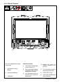
4-13. Setting Help Menu Language And Viewing Help Menu
1
Information
Control
Button
2 Directional Buttons
3 OK Button
Press Auto On/Off but-
ton to turn helmet on.
Press Information but-
ton repeatedly until Lan-
guage is displayed on
screen.
Use up/down arrows to
select desired lan-
guage. Press OK to
save.
Press the Information
Control button once.
Help menu will now be
shown in the desired
language.
To navigate the Help
menu, use either the up/
down arrows or the left/
right arrows. To exit,
press the Auto On/Off
button.
Help menu displays
abbreviated instructions,
modes, and notes on
proper usage. Help menu
should not be used as a
replacement for the full
manual.
1
2
3
Page is loading ...
Page is loading ...
Page is loading ...
Page is loading ...
Page is loading ...
Page is loading ...
Page is loading ...
Page is loading ...
-
 1
1
-
 2
2
-
 3
3
-
 4
4
-
 5
5
-
 6
6
-
 7
7
-
 8
8
-
 9
9
-
 10
10
-
 11
11
-
 12
12
-
 13
13
-
 14
14
-
 15
15
-
 16
16
-
 17
17
-
 18
18
-
 19
19
-
 20
20
-
 21
21
-
 22
22
-
 23
23
-
 24
24
-
 25
25
-
 26
26
-
 27
27
-
 28
28


Miller INFINITY WELDING HELMET - CAT Owner's manual
- Category
- Welding System
- Type
- Owner's manual
- This manual is also suitable for
Ask a question and I''ll find the answer in the document
Finding information in a document is now easier with AI
Related papers
-
Miller MH000000 Owner's manual
-
-
-
-
-
-
-
-
-
Miller HELMET PRO-HOBBY/PERFORMANCE Owner's manual
Other documents
-
HobartWelders HELMET INVENTOR AUTO-DARKENING Owner's manual
-
-
WIA ViewFX Owner's manual
-
-
Hobart HELMET ENDEAVOR SERIES AUTO-DARKENING Owner's manual
-
-
-
Lincoln Electric VIKING 2450D Operating instructions
-
Hobart Hood XVX User manual
-
METAL MAN ATEC8735SGC User manual