
L.R CONVERSION
INSTRUCTIONS
WARNING: This conversion
must be performed bg a
qualified installer or gas
supplier in accordance with the
manufacturer's instructions and
all codes and requirements of
the authoritg having jurisdiction.
Failure to follow ALL
instructions could result in
serious injurg or propertg
damage.
The qualified agencg
performing this work assumes
responsibilitg for the conversion.
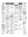
The pressure regul(]tor (]nd the
burner orifices (]re set for n(]tur(]l
g(]s. To use Liquid Prop(]ne Gas,
the regul(]tor (]nd burner orifices
must be converted. The L.R
orifices for the cooktop burners
(]re shipped on the regul(]tor
bracket behind the stor(]ge
drGwer. Also, in the s(]me (]re(], is
(] second brGcket holding the L.R
15K orifice extended spud, choke
(]nd set screw for the front right
Extr(] L(]rge cooktop burner {on
models so equipped). Remove the
stor(]ge dr(]wer to Ioc(]te.
Do not operate the
cooktop or oven burners
of this range when using
L.P. (bottled) gas before
converting the pressure regulator
and burner orifices for L.P. gas use.
Failure to do so could cause high
flames and toxic fumes which can
result in serious injury.
To adjust your range for use with
/.R gas, follow these instructions:
1. Disconnect all electrical power,
at the main circuit breaker or fuse
box.
2. Shut off the gas supply to the
range by closing the manual
shut-off valve.
a,
Remove the storage drawer,
kick panel and if applicable
the access panel to access
the regulator. (Some models
will have a metal shield
protecting the regulator that
must be removed for
conversion and reinstalled
when conversion is
complete.) The pressure
regulator is located in the
lower, left hand rear corner of
the range as viewed from the
Bracket-LP Orifice Spud
Pressure Regulator
Gas valve
/
r
_ CAUTION: If you are
>using L.P. (bottled) gas, all
adjustments described in
the following steps must be made
before you make any burner
adjustments.
b. Unscrewthe plastic-
protected hex-nut cap.
c. Completely remove the
protective plastic cap off the
threaded metal cap.
d. Turn the metal cap so the
type of gas being converted
to is displayed and replace
the protective plastic cover.
e. Screw the hex-nut cap back
into the regulator. (Do not
over tighten)
Rotate Cap counter
clockwise to l....._@__kp_
Cap Assembly
Lever shown closed (Oven ShutO ffonly).
PUSH LEVER TOWARD REGUL ATOR TO OPEN.
a,
Remove the top grates,
burner caps and burner
heads.
Front right burner (on some
models), front left, back right,
back left and center burners.
Burner Cap
ORIFICE
SPUD
LOCATED
THRU THIS
OPENING
b. Using a 7 mm or 9/32" nut
driver, remove the top burner
orifices. These may be
accessed through the burner
opening in the base.
I_ IMPORTANT: ol
Save these orifices for
future conversion back t
natural gas.
c. locate the 1.P.orifices. The
/.R orifices for the cooktop
burners are shipped on the
regulator bracket behind the
storage drawer. Also, in the
same area, is a second
bracket holding the L.R 15K
orifice extended spud, choke
and set screw for the front
right Extra Large cooktop
burner (on models so
equipped). Remove the
storage drawer to locate.
d. Remove the LP orifice spuds,
from the metal bracket. LP
orifice spuds have the letter
"L" on the top.
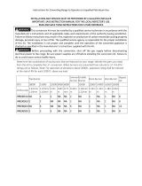
To aid in identifying the proper
location for the/P orifices during
a conversion from Natural Gas to
I_PGas,paint color codes have
been added to the side or top of
the orifice. See the chart in the
next column. Each orifice may
also show a series of engraved
marks (I, II, III ..)located on the
_ enotes 0.95mm Orifice size opening
Denotes LP(Propane) Gas
e.
BTU
BURNER RATE COLOR
RF 9,500 Blue/Brown
LF 9,500 Blue/Brown
LR 9,500 Blue/Brown
RR 5,000 Blue/Brown
Installthe L.Rorifices in their
precise locations.
To prevent leakage, make sure the
orifice spuds are securely screwed
into the gas supply tubes.
f. Install the old orifice spuds
into the metal bracket and
replace both metal brackets
back on the range for possible
future conversion.
g. Return the natural orifices to
the bracket and reattach the
bracket and these instructions
to the range using the screw
previously removed.
r
_-_ CAUTION:The
following
\ _'/adjustments must be made
before turning on the gas to
the burner. Failure to do so could
result in serious injury due to high
flames and toxic fumes.
,
,
BAKE BURNER ORIFICE
Remove oven door, drawer
and oven bottom. The lower
burner orifice hood is located
behind the drawer (on some
models a metal shield must
be removed).
To convert to LID,use a 1/2"
wrench to turn the lower
burner orifice hood clockwise
(When viewed from above)
until it is snug with the base,
approximately 2 1/2 turns.
(To prevent damage when
converting back to Natural
Gas, do not over tighten the
hood.)
The oven bake burner assembly
is located at the lower rear
compartment.
BROIL BURNERORIFICE
(on some models)
To convert to LP gas, use a 1/2"
wrench to turn the upper burner
orifice hood clockwise. Tighten
the orifice hood until it is snug
with the base.
(Toprevent damage when
conver-ting back to Natural Gas,
do not over tighten the hood.)
AIR SHUTTER SETTINGS FOR
BAKE AND BROIL BURNERS
1. Use a screwdriver to loosen
the air shutter screw.
2. Adjusttheair I t !!
for LP gas, Air S_ _J
by rotating
the shutter to the fully open
position. Your final settings
may vary.
3. Retighten the air shutter screw.
Bake and broil flame must be
checked with the door closed to
properly check flame
characteristics.
,
5.
6.
7.
,
Turn on the gas.
Turn on the electricity.
Reinstall the oven door.
Turn on the bake or broil
burner.
As you watch the flame with
the oven door closed, check
the following through the
oven door window:
a. If the flames are yellow,
open the air shutter more.
b. If the flames blow away
or flutter from the burner,
close the air shutter more.
31-21390
MP-00

WARNING: 1
I Y/If youattemp to measure
I _ the inner cone of the
|flame, please use caution; burns
Lcould result.
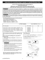
9. Checking the flame size:
Check the inner cone of the flame.
It should be approximately 1/2"to
%" long for the bake and broil
burners.
//INNER CONE
F OF FLAME
3/4" _ _ OVEN / BROIL
1/2 " to __
The combustion quality of the
burner flames need to be
determined visually.
NOTE: If burner flames look like
(A). Further air shutter adjust-
ment is required. Normal burner
flames should look like (B) or (C),
depending on the type of gas
you use.WithLPgas,some
yellow tipping on the outer
cones is normal.
(B)Yellow tips on
outer cones:
Normal for LP Gas
(C) Soft Blue Flames:
Normal for Natural Gas.
10. When all adjustments are
made and the results are
satisfactory
a. Replace the orifice fitting cover.
b. Replace the oven baffle (flame
spreader).
c. Replace the oven bottom.
IN SOME CASES:
a.With L.P.gas,someyellow
tipping on the outer cone is
normal.
b. Foreign particles in the gas line
may cause an orange flame at
first, but this will soon disappear.
SPECIALNOTE:
Toconvert the oven back to natural
gas, reverse the instructions given
inmaking L.P.Adjustments.
NOTE: On some models the front
right burner can not be adjusted.
Low setting adjustments must be
made with two other burners in
operation on a medium setting.
This procedure prevents the low
flame from being set too low,
resulting in the flame being
extinguished when other burners
are turned on.
a,
b.
C,
Turn on all surface burners.
Turn the knob on the burner
being adjusted to "LO" (LOW).
Remove the knob and insert a
small, flat blade screwdriver
into the valve shaft as shown
and turn clockwise to fully
tighten down the bypass
screw. Repeat for each screw.
Centeradjustmentscrew
d,
If flame appears too low or
unstable, adjust valve bypass
screw slowly (turn
counterclockwise--CCW) until
a stable flame exists for each
burner. Remember two other
burners must be turned on to
medium.
e. Additionally, for each burner
being adjusted, quickly open
and close the oven door
followed by the storage
drawer while observing flame.
If flame is extinguished,
continue adjusting bypass
screw CCW for larger flame.
Repeat door and drawer
openings until flame is stable.
f. Replacethe knob.
Once the conversion is
complete and checked ok,
fill out the L.P. Sticker and
include your name, organization
and date conversion was made.
Apply the sticker to the range
near the regulator to alert others
in the future that this appliance
has been converted to L.P. If
converting back to natural gas
from L.P., please remove the
sticker so others know the
appliance is set to use natural gas.
BURNER OUTPUT RATINGS:
BTU/HR
BTU
BURNER RATE ORIFICESIZE
RF 9,500 0.035" (0.89mm)
LF 9,500 0.035" (0.89mm)
LR 9,500 0.035" (0.89mm)
RR 9,500 0.035" (0.89mm)
BAKE* 16,000 #56 (0.0465'_
+BROIL* 12,000 #59 (0.041'1
+If so equipped
* Oven burner(s) use convertible
hood(s) and are simply adjusted
for conversion.
_ enotes 0.95mm Orifice size opening
Denotes LP (Propane) Gas
BURNEROUTPUTRATINGS:
BTU/HR
BTU
BURNER ORIFICESIZE
RATE
RF 9,500 0.049" (1.24mm)
LF 9,500 0.049" (1.24mm)
LR 9,500 0.049" (1.24mm)
RR 9,500 0.049" (1.24mm)
BAKE* 16,000 #48 (0.076")
BAKE* 18,000 #46 (0.081")
+BROIL* 12,500 #51 (0.067'_
~For standard models.
+ If so equipped.
* Oven burner(s) use convertible
hood(s) and are simply adjusted for
conversion.
_ Denotes 1.98mm Orifice size opening
Denotes Natural Gas
TOOLS REQUIRED:
Adjustable wrench
1/2"open-end wrench
Phillips head screwdriver
Flat bladed screwdriver (blade
width approximately 3/32"
across)
Nut drivers: 9/32" or 7mm
L.P.CONVERSION
INSTRUCTIONS
183D5578P076
31-21390
MP-00
03-17 CR
-
 1
1
-
 2
2


Hotpoint RGB735WEL8WW Installation guide
- Type
- Installation guide
- This manual is also suitable for
Ask a question and I''ll find the answer in the document
Finding information in a document is now easier with AI
Other documents
-
Kenmore 79075741991 Installation Instructions Manual
-
GE RGA824DEDWW LP Conversion Kit
-
-
-
NXR NKLP3611 Operating instructions
-
 Thor Kitchen LPKHRG3618U Operating instructions
-
Whirlpool SF372BEE Q/Z User manual
-
Kenmore Elite 79079463602 Installation guide
-
 Kenmore Elite 79077492800 Installation guide
-
Whirlpool 8053365 User manual

