ZM 122 Audio Mixer
User Manual
Order code: CRAM36

www.cleveracoustics.co.uk ZM 122 Audio Mixer User Manual
2
Safety advice
WARNING
FOR YOUR OWN SAFETY, PLEASE READ THIS USER MANUAL
CAREFULLY BEFORE YOUR INITIAL START-UP!
• Before your initial start-up, please make sure that there is no damage caused during transportation.
• Should there be any damage, consult your dealer and do not use the equipment.
• To maintain the equipment in good working condition and to ensure safe operation, it is necessary
for the user to follow the safety instructions and warning notes written in this manual.
• Please note that damages caused by user modications to this equipment are not subject to warranty.
IMPORTANT:
The manufacturer will not accept liability for any resulting damages caused by the non-observance
of this manual or any unauthorised modication to the equipment.
OPERATING DETERMINATIONS
If this equipment is operated in any other way, than those described in this manual, the product may suffer damage and
the warranty becomes void. Incorrect operation may lead to danger e.g: short-circuit, burns and electric shocks etc.
Do not endanger your own safety and the safety of others!
Incorrect installation or use can cause serious damage to people and/or property.
• Speaker & Amplier systems can produce high sound
pressure levels, please operate all controls with caution to
ensure people are not exposed to excessive or dangerous
sound pressure levels.
• Never let the power cable come into contact with other
cables. Handle the power cable and all mains voltage
connections with particular caution!
• Never remove warning or informative labels from the unit.
• Do not open the equipment and do not modify the unit.
• Do not switch the equipment on and off in short intervals,
as this will reduce the system’s life.
• Only use the equipment indoors.
• Do not expose to ammable sources, liquids or gases.
• Always disconnect the power from the mains when
equipment is not in use or before cleaning! Only handle
the power-cable by the plug. Never pull out the plug by
pulling the power-cable.
• Make sure that the available voltage
is between 220-240V, 50/60Hz AC or 24V DC.
• Make sure that the power cable is never crimped or
damaged. Check the equipment and the power cable
periodically.
• If the equipment is dropped or damaged, disconnect the
mains power supply immediately and have a qualied
engineer inspect the equipment before operating again.
• If the equipment has been exposed to drastic
temperature uctuation (e.g. after transportation),
do not connect power or switch it on immediately.
The arising condensation might damage the equipment.
Leave the equipment switched off until it has reached
room temperature.
• If your product fails to function correctly, stop use
immediately. Pack the unit securely (preferably in the
original packing material), and return it to your Prolight
dealer for service.
• Only use fuses of same type and rating.
• Repairs, servicing and power connection must only be
carried out by a qualied technician. THIS UNIT CONTAINS
NO USER SERVICEABLE PARTS.
• WARRANTY: Three years from date of purchase.
CAUTION!
KEEP THIS EQUIPMENT
AWAY FROM RAIN,
MOISTURE AND LIQUIDS
CAUTION!
TAKE CARE USING
THIS EQUIPMENT!
HIGH VOLTAGE-RISK
OF ELECTRIC SHOCK!!

www.cleveracoustics.co.uk ZM 122 Audio Mixer User Manual
3
Product overview & technical specications
Suitable for use in a wide range of applications, the ZM 122 offers the user a clean, simple control surface while
retaining a large number of features for complex audio systems. The ZM 122 mixer has 9 input channels, each
with adjustable volume controls. Six of the channels are microphone inputs with XLR 1/4” combo sockets, the
other three are RCA line level stereo inputs. Adding to the features, the ZM 122 has a 3 band EQ, mono out and
microphone out all in a 1U 19” rack mount unit.
• Six mono channels with combo XLR/Jack input, each with
Mic/Mic+ Phantom/Line selector
• Three stereo line level inputs via phono sockets
• Low distortion microphone pre-amplifiers
with high dynamic range
• CH level control, signal LED to indicate input signal
• Microphone 1 features adjustable priority override
• Input level control with input signal LED
• Stereo line output via balanced XLRs
• Mono output via 6.35mm (1/4”) unbalanced jack with
volume control
• Microphone mix output via 6.35mm (1/4”) unbalanced jack
with volume control
• Microphone mix output via 6.35mm (1/4”) unbalanced jack
with volume control
• Microphone mix output via 6.35mm (1/4”) unbalanced jack
with volume control and on/off switch
• Stereo record output via unbalanced phono sockets
• 3-band EQ for low, mid, high
• Master volume control
• 4-segment LED signal level meters
• AC 220V-240V or DC 24V operating voltage
• 1U 19” rackmount chassis with brushed
aluminium front panel
ZM 122 Audio Mixer
ZM 122
Audio Mixer
SIG
CH 6
SIG
CH 5
SIG
CH 4
SIG
CH 3
SIG
CH 2
SIG
CH 1
SIG
CH 7/8
SIG
CH 9/10
SIG
CH 11/12
OUT OUT
ON
OFF
CLIP
10dB
0dB
SIG
OFF
POWER
ON
-10 +10
BASS MID TREBLE
L R
MICMIC INPUTS MONO MASTERSTEREO INPUTS EQUALISER
0 10 0 10 0 10 0 10 0 10 0 10 0 10 0 10 0 10
0 10 0 10
OUT
0 10
-10 +10 -10 +10
44mm
484mm
238mm
Specications ZM 122 Audio Mixer
Mono input channels (CH1-CH6)
Microphone input Electronically balanced, discrete input conguration
Frequency response 20Hz-22kHz +/-2dBu
Distortion (THD) ≤0.03% @ 1kHz
Sensitivity -40dBu
Max. input -19dBu
Max. voltage gain 60dB CH MIC input - MAIN output (XLR, balanced)
50dB CH MIC input - REC output (unbalanced)
60dB CH MIC input - MIC output (unbalanced)
60dB CH MIC input - MONO output (unbalanced)
Signal to noise ratio ≥103dB
Phantom power
(Mic Pin2/Pin 3 & Pin 1)
+18V~21V with switch control

www.cleveracoustics.co.uk ZM 122 Audio Mixer User Manual
4
Technical specications
Specications ZM 122 Audio Mixer
Mono input channels (CH1-CH6)
Line input Electronically balanced
Frequency response 20Hz-22kHz +/-2dBu
Distortion (THD) ≤0.03% @ 1kHz
Sensitivity 0dBu
Max. input +21dBu
Max. voltage gain 20dB CH MIC input - MAIN output (XLR, balanced)
10dB CH MIC input - REC output (unbalanced)
20dB CH MIC input - MIC output (unbalanced)
20dB CH MIC input - MONO output (unbalanced)
Stereo input channels (CH7-CH12)
Line input Electronically balanced
Frequency response 20Hz-22kHz +/-2dBu
Distortion (THD) ≤0.03% @ 1kHz
Sensitivity +10dBu
Max. input +21dBu
Max. voltage gain 10dB CH MIC input - MAIN output (XLR, balanced)
0dB CH MIC input - REC output (unbalanced)
4dB CH MIC input - MONO output (unbalanced)
Signal to noise ratio ≥103dB
Impedance
Microphone input 1.4kΩ
All other inputs ≥10kΩ
All other outputs 120Ω
Equaliser
High ±15dB @ 12kHz
Mid ±12dB @ 2.5kHz
Low ±15dB @ 80Hz
Crosstalk
Adjacent input ≤-70dB @ 1kHz (CH1-CH6)
≤-68dB @ 1kHz (CH7-CH12)
Input to output ≤-82dB @ 1kHz (CH level at max, EQ at mid, MAIN level and
other at min, sw at LINE)
Main mix selection
Line output 0dBu (±2dBu) Balanced (CH level & MAIN & EQ at mid, other
at min, sw at LINE)
MIC output, MONO output 0dBu (±2dBu) Unbalanced, 1/4" jacks (CH level & MAIN &
EQ at mid, other at min, sw at LINE)
Max. output +21dBu Balanced/unbalanced, 1/4" jacks
Noise (busnoise) ≤-83dB @ 20Hz~22kHz (channel & MAIN level & EQ at mid,
other at min, sw at LINE)
Dielectric strength
Between Live+Negative to Earth 1500VAC at test frequency 50/60Hz
Leakage current: 5mA for 1 minute
Between Live+Negative to IN/OUT terminal
(Positive+Negative)
3000VAC at test frequency 50/60Hz
Leakage current: 5mA for 1 minute
Insulation resistance
Between Live+Negative to Earth (500VDC) >2MΩ
Between Live+Negative to IN/OUT terminal
(Positive+Negative) (500VDC)
>4MΩ
Power consumption 35W
Power supply 220-240V AC 50/60Hz or 24V DC
Fuse T315mA 250V
Dimensions 44 x 484 x 238mm
Weight 3.9kg
Order code CRAM36

www.cleveracoustics.co.uk ZM 122 Audio Mixer User Manual
5
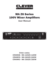
Panel & connection identication
01 - MIC Input Volume Controls
02 - Signal LED
03 - MIC/LINE Switchable Button
and Volume Control
04 - Equaliser (LOW, MID, HIGH)
05 - Mono Volume Control
06 - L/R LED Output Meter
07 - Master Volume Control
08 - Power Switch and LED Indicator
09 - 19" Mounting Ears
Front Panel Layout:
POWER INPUT: 220-240V~50/60Hz FUSE: T315mA 250V
POWER CONSUMPTION (max.): 18W
MIC
PHANTOM
MIC 1
PRIORITY
LINE
CH 6
CH 7/8CH 9/10CH 11/12REC OUTPUTMIC
OUTPUT
MONO
OUTPUT
LEFTRIGHT
MIC
PHANTOM
LINE
CH 5
MIC
PHANTOM
LINE
CH 4
MIC
PHANTOM
LINE
CH 3
MIC
PHANTOM
LINE
CH 2
MIC
PHANTOM
LINE
CH 1
MIC / LINE INPUTSLINE INPUTS
R
L
LINE OUTPUTS
DC 24V 500mA
+
–
ZM 122
Audio Mixer
0 10
SIG
CH 6
0 10
SIG
CH 5
0 10
SIG
CH 4
0 10
SIG
CH 3
0 10
SIG
CH 2
0 10
SIG
CH 1
0 10
SIG
CH 7/8
0 10
SIG
CH 9/10
0 10
SIG
CH 11/12
0 10
OUT
0 10
OUT
0 10
OUT
ON
OFF
CLIP
10dB
0dB
SIG
OFF
POWER
ON
-10 +10 -10 +10 -10 +10
BASS MID TREBLE
L R
MICMIC INPUTS MONO MASTERSTEREO INPUTS EQUALISER
01
05 07 09
02 03 04 06 08
POWER INPUT: 220-240V~50/60Hz FUSE: T315mA 250V
POWER CONSUMPTION (max.): 18W
MIC
PHANTOM
MIC 1
PRIORITY
LINE
CH 6
CH 7/8CH 9/10CH 11/12REC OUTPUTMIC
OUTPUT
MONO
OUTPUT
LEFTRIGHT
MIC
PHANTOM
LINE
CH 5
MIC
PHANTOM
LINE
CH 4
MIC
PHANTOM
LINE
CH 3
MIC
PHANTOM
LINE
CH 2
MIC
PHANTOM
LINE
CH 1
MIC / LINE INPUTSLINE INPUTS
R
L
LINE OUTPUTS
DC 24V 500mA
+
–
ZM 122
Audio Mixer
0 10
SIG
CH 6
0 10
SIG
CH 5
0 10
SIG
CH 4
0 10
SIG
CH 3
0 10
SIG
CH 2
0 10
SIG
CH 1
0 10
SIG
CH 7/8
0 10
SIG
CH 9/10
0 10
SIG
CH 11/12
0 10
OUT
0 10
OUT
0 10
OUT
ON
OFF
CLIP
10dB
0dB
SIG
OFF
POWER
ON
-10 +10 -10 +10 -10 +10
BASS MID TREBLE
L R
MICMIC INPUTS MONO MASTERSTEREO INPUTS EQUALISER
10 - AC Mains Power Input with Fuse
11 - DC Power Supply
12 - LINE Outputs
13 - MONO Output
14 - MIC Output
15 - REC Outputs
16 - LINE Inputs 7/8, 9/10, 11/12
17 - LINE/MIC/PHANTOM Switches
18 - MIC/LINE Inputs 1-6
19 - MIC 1 Priority Potentiometer
10 1911 13 14 15 16 18 1712
Rear Panel Layout:
Layout identication:
01. MIC Input Volume Control
MIC channel 1 would have priority over other MIC input channels. This function can be disabled by
adjusting the MIC priority knob at the back of the unit. When the knob is turned anti-clockwise to the
leftmost position, a signal received by the Channel 1 MIC/LINE input will not affect the other input
signals at all. Turning the knob from the leftmost position towards the right position will gradually have
the Channel 1 MIC/LINE input volume take priority over all other input signals. When the knob is turned
to the rightmost position, a signal received by the Channel 1 mic/LINE input will mute all other input
signals entirely. The rotary knobs for microphone inputs 1 to 6, 7/8, 9/10 ,11/12 are for adjustment of
input signal levels. In setup, adjust this gain to the optimum level according to the required output level.
Different channel may have different input source (ie: condenser or dynamic MIC, etc).

www.cleveracoustics.co.uk ZM 122 Audio Mixer User Manual
6
Operating instructions
02. Signal LED
The presence of the input signal is indicated at this LED. The LED will ash or illuminate to show the
channel’s incoming audio signal is within an optimal range.
03. MIC/LINE Switchable Button & MIC Output Volume Control
Press this to turn enable or disable the MIC output. When the button is depressed (in the down position),
the signal from the MIC/LINE inputs (Channels 1–6) will be sent to the MIC Monitor output, and the
LINE Outs will be disabled. When the button is raised (in the up position), the MIC Monitor output will be
disabled, and all channels will be sent to the LINE Outs.
04. Equaliser
Turn these knobs to increase (“boost”) or reduce (“cut”) the amount of bass frequencies (LOW),
mid-range frequencies (MID), and treble frequencies (HIGH) of the main mix.
LOW
This is the bass control. It is used to boost male voice, kick-drum or bass guitar. Your system will sound
much bigger than what it is. The gain range goes from -15dB to +15dB with a centre frequency of 80Hz.
MID
This is the midrange control. It provides -12dB to +12dB boost or cut with a centre frequency of 2.5kHz.
It can affect most fundamental frequencies of all musical instruments and human voice.
HIGH
This is the treble control. You can use it to get rid of high frequency of human voice or instruments.
The gain range goes from -15dB to +15dB with a centre frequency of 12kHz.
05. Mono
The level control knob sets the level of mono output signal, ranging from –
∞
to +10dBu.
06. L/R LED Output Meter
The LED meter indicates the level of output signal, this will illuminate green under normal conditions or
amber when the signal is high. Also a clipping indicator will indicate red when the output is too high.
07. Master Volume Control
This knob is used for adjusting the LINE output level. To avoid over amplication, it's recommended that
this level be set properly. It is advisable that the gain be set to minimum when powering the system on
or off as this can eliminate sudden signal peaks to your system which could damage loudspeakers or
ampliers.
08. Power Switch & LED Indicator
This switch controls to power on/off the unit. When the unit is switched on, the LED will light up. The unit
is also provided a 24V DC backup power supply. Then the switch will control its on/off.

www.cleveracoustics.co.uk ZM 122 Audio Mixer User Manual
7
Operating instructions
09. 19" Mounting Ears
The mounting ears are adopted to easily install the unit in a rack enclosure. Care should be taken to
install the ZM 122 with adequate space between other items in the rack to avoid overheating.
10. AC Mains Power Input
This connector is meant for the connection of the supplied power cord. Please check the supply voltage
accepted by the unit (220-240V AC~50/60Hz) and the voltage available from AC sockets before
connecting the unit to the mains power. This product falls under CLASS 1 and must have a protective
earth connection at all times.
11. DC Power Input
For connection to battery backup power sources, or for operation from leisure type batteries.
The ZM 122 mixer may be used from 24V DC power sources. Care should be taken to ensure an inline
fuse is tted to the +ve supply and the power is connected with observing the polarity. When both the
AC and DC source is connected, the ZM 122 shall operate using AC mains whereas the DC supply shall
be only consumed whenever the AC supply fails or is disconnected.
12. LINE Outputs
Stereo outputs via male XLR connectors for connection to ampliers or recording sources.
Connection should be made using high quality, balanced XLR cables.
13. MONO Output
A mono sum output of the main L/R mix via a 6.35mm (1/4") unbalanced TRS jack connector.
The output level for this output may be adjusted using the MONO control on the front panel.
14. MIC Output
A mono sum output of the main L/R mix via a 6.35mm (1/4") unbalanced TRS jack connector.
The output level for this output may be adjusted using the MIC control on the front panel.
15. REC Output
Unbalanced phono (RCA) sockets are to be connected to recording media such as cassette tape
recorder. The source for this output is replicated from the main L/R mix.
16. LINE Inputs
Unbalanced phono (RCA) sockets (for stereo music sources). The left and right channels are combined,
resulting in a single mono signal that can be directed to one or two the audio outputs.
17. LINE/MIC/PHANTOM Switches
Use these switches to set what type of audio source is connected to each MIC/LINE input: a microphone
without phantom power (MIC), a microphone with +18~21V of phantom power (PH), or a line-level
device (LINE).
Note: Most dynamic microphones do not require phantom power, while most condenser microphones
do. Consult your microphones documentation to nd out whether it requires phantom power.

www.cleveracoustics.co.uk ZM 122 Audio Mixer User Manual
8
Operating instructions
18. MIC/LINE Inputs
Balanced/unbalanced XLR/jack combo connectors are used for the MIC/LINE signal input.
Each input maybe switched from LINE, MIC or MIC with PHANTOM POWER.
19. MIC 1 Priority Potentiometer
The muting circuitry activates in the presence of signal from MIC 1. This potentiometer determines the
mixing level of MIC or LINE input signals with signals of priority channels. Setting it to minimum shall cut
off all other inputs when signal is presence in priority channel (MIC 1), whereas setting it to maximum
shall allow free mix of all signals including priority input. Some applications may not require this feature,
such as in a hall of prayer, thereby to bypass the circuitry, adjust the level to the maximum.

www.cleveracoustics.co.uk ZM 122 Audio Mixer User Manual
9
Block Diagrams
Block Diagram:

www.cleveracoustics.co.uk ZM 122 Audio Mixer User Manual
10
Typical panel connections
Typical Panel Connections:
PH
PH
PH
PH
PH
PH

www.cleveracoustics.co.uk ZM 122 Audio Mixer User Manual
11
Application examples
Application example - Paging System:
Application example - Lecture Hall/Conference Room:

www.cleveracoustics.co.uk ZM 122 Audio Mixer User Manual
12
WEEE notice
Correct Disposal of this Product
(Waste Electrical & Electronic Equipment)
(Applicable in the European Union and other European countries
with separate collection systems)
This marking shown on the product or its literature, indicates that it should not be disposed
with other household wastes at the end of its working life. To prevent possible harm to the
environment or human health from uncontrolled waste disposal, please separate this from other
types of wastes and recycle it responsibly to promote the sustainable reuse of material resources.
Household users should contact either the retailer where they purchased this product, or their
local government ofce, for details of where and how they can take this item for environmentally
safe recycling.
Business users should contact their supplier and check the terms and conditions of the
purchase contract. This product should not be mixed with other commercial wastes for disposal.
/