Page is loading ...

INSTALLATION AND SERVICE MUST BE PERFORMED ElYA QUALIFIED INSTALLER.
iMPORTANT: SAVE FOR LOCAL ELECTRICALINSPECTOR"SUSE.
READ AND SAVE THESE INSTRUCTIONS FOR FUTURE REFERENCE.
1
If the information in this manual is not followed exactly, a fire
or explosion may result causing property damage, personal injury or death. I
FOR YOUR SAFETY:
-- Do not store or use gasoline or other flammable vapors and liquids in
the vicinity of this or any other appliance.
-- WHAT TO DO iF YOU SMELL GAS:
* Do not try to light any appliance.
* Do not touch any electrical switch; do not use any phone in your building.
o immediately call your gas supplier from a neighbor's phone. Follow the
gas supplier's instructions.
if you cannot reach your gas supplier, call the fire department.
-- installation and service must be performed by a qualified installer,
service agency or the gas supplier.
Refer to your serial plate for
applicable agency certitication
Appliances installed in the
state of Massachusetts:
This Appliance can only be installed
in the state of Massachusetts by a
Massachusetts licensed plumber or
gasfitter.
This appliance must be installed
with a three (3) foot / 36 in. long
flexible gas connector.
A"T" handle type manual gas valve
must be installed in the gas supply
line to this appliance.
Do not install the unit in the
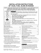
cabinet before reading next page. 30" Min.
(76.2 cm Min.),
5" Min _ (33 cm)
Shave 1V21 Max_ From(12.7waCmBothMin.)_Ides/__ (45!78cm_'Min.
Raised (3.8cm Max.)
Edge _ I .......
to Clear ,/ X _ ___ -li/4" rnin,_/
Cooktop. _ | _ Approx. 1 7/8"
J F ]] ::
Locate Cabinet Doors 1" (2.5 J __::::'_: __ .......... i
cm) Min. from Cutout Opening. _ ___ W j .............. /_
Grounded Jonction Box or Wall Outlet Should Be
Located 8" to 17" (20.3 cm to 43.2 cm) From Right
Cabinet and 2" to 4" (5.1 cm to 10.2 cm) From Floor.
A HEIGHT
(Under Cooktop)
35 7/8" (91,1 cm)
36 518" (93 cm)
NOTE: Wiring diagram for these appliances are enclosed in this booklet.
Printed in United States
B. WIDTH C: COOKTOP D: TOTAL DEPTHTO E. CUTOUT WIDTH*** F: CUTOUT G. HEIGHT
[WIDTH i ERQNTOF RANGE (Counter[op DEPTH OF COUNTERTOP
and Cabinet) i
30" (76,2 cm) 31 1/2" 285/16" (71,9 cm) 30_+1/16" 21 3/4" (55,2 cm) Min. 357/8" (91,1 cm) Min.
(80 cm) (76,2_+0,15cm) 22 1/8" (56,2 cm) Max
24" (61 cm) Min. with 36 5/8" (93 cm) Max.
backguard
P/N 318201680 (0903) Rev. A
English- pages 1-12
Espaflol - p_iginas 13-24
Fran_ais - pages 25-36

NOTE:
1. Do not pinch the power supply cord or the
flexible gas conduit between the range and
the wall.
2. Do not seal the range to the side cabinets.
3.24" (61 cm) minimum clearance between
the cooktop and the bottom of the
cabinet when the bottom of wood or
metal cabinet is protected by not less than
¼" (0.64 cm) flame retardant millboard
covered with not lessthan No. 28 MSG
sheet metal, 0.015 "(0.4 ram) stainless
steel, 0.024"(0.6 ram) aluminum, or
0.020" (0.5 ram) copper.
30" (76.2 cm) minimum clearance when
the cabinet is unprotected.
4. For cutouts below 22 7/8"(58.1 cm),
appliance will slightly show out of the
cabinet.
5.Allow at least 19 ¼" (48.9 cm) clearance
for door depth when it is open.
Door Open
/
I
Panel
*** IMPORTANT: To avoid cooktop breakage for cutout width (E dimension) of more
than 30 1/16" (76,4 cm), make sure the appliance is centered in the counter opening
while pushing into it. Raise leveling legs at a higher position than the cabinet height
(see page 3), insert the appliance in the counter and then level. Make sure the unit
is supported by the leveling legs and NOT by the cooktop itself.
IM PORTANT: Cabinet and countertop width
should match the cutout width.
E
E
22 7/8"(58.1 cm) min.
23 1/4"(59.05 cm) max.
- (see Note 4) -_
__| _ 1 118"
' (2.86 cm)
FRONT OF
CABINET _ FRef.--
r
A HEIGHT ' B:WIDTH " C: CooKToP D. TOTAL DEPTHTO E. CUTOUTWIDTH***. F: CUTOUT I G: HEIGHT
(Under Cooktop) , WIDTH FRONTOF RANGE (Countertop ] DEPTH OF COUNTERTOP
I ! ! I and cabinet) i i
35 7/8" (91,1 cm) 30"(76,2cm) 31 1/2" 28 5/16" (71,9cm) 30_+1/16" 21 3/4" (55,2cm) Min. 35 7/8" (91,1 cm) Min.
(80 cm) (76,2_+0,15 cm) 22 1/8" (56,2 cm) Max
36 5/8" (93 cm) 24" (61 cm) Min. with 36 5/8" (93 cm) Max.
backguard

To avoid breakage: Do NOT handle or
manipulate the unit by the cooktop.
The counter-top around the cut-out should be flat and leveled
(see hatched area on illustration 1).
Before installing the unit, measure the heights of the two (2) cabi-
net sides (H1-4), front and back (see illustration 1) from the floor
to the top of the counter•
Level the range using the
four (4) leveling legs, so
that the height from the
floor to the underside of
the metal flange is greater
than the tallest cabinet
measurement by at least
1/16" (see illustration 2).
Shave
Raised
Edge
to Clear
Space for a
1 1/2"Max. I
(3.8 crnMax.) I
311/2" (81 cm)
Wide Cooktop.
Slide the unit into the cabinet• Make sure the center of the unit is
aligned with the center of the cabinet cut-out•
Remove the protective channels on each side of the cooktop
(if provided)•
The metal flange under each side of the cooktop MUST be placed /
over the cabinet countertop for proper unit support• The cooktop
should NOT rest directly on the countertop (see illustration 2) or else
it could cause damage to the cooktop voiding the warranty• Level the
unit if needed•
After the installation, MAKE SUREthat
the unit issupported by the two front
leveling legs and the two adjustable
leveling wheels
and NOT by the
cooktop.
\
Illustration 1
1
successfully
"install the range,
the initial level
height from floor
to underside of
cooktop frame
should be at least
1/16" taller than
cabinet sides as
measured in step
2.
Illustration 2
3

important Notes to the Installer
1. Read all instructions contained in these installation
instructions before installing range.
2. Removeall packing material from the oven compartments
before connecting the gas and electrical supply to the
range.
3. Observe all governing codes and ordinances.
4. Be sure to leave these instructions with the consumer.
5. Note: For operation at 2000 ft. elevations above see
level, appliance rating shall be reduced by 4 percent for
each additional 1000 ft.
important Note to the Consumer
Keep these instructions with your Owner's Guide for the
local electrical inspector's use and future reference.
IMPORTANT SAFETY
INSTRUCTION
_l_i_lCold temperatures can damage the
electronic control. When using the appliance for the first
time, or when the appliance has not been used for an
extended period of time, be certain the unit has been
in temperatures above 32% (0°C) for at least 3 hours
before turning on the power to the appliance.
Installation of this range must conform with local codes
or, in the absence of local codes, with the National Fuel
Gas Code ANSI Z223.1 / NFPA54 or CAN/ACG-B149.1
and CAN/ACG-B149.2.
This range has been design certified by CSA
international. As with any appliance using gas and
generating heat, there are certain safety precautions you
should follow. You will find them in the Use and Care
Guide, read it carefully.
• Be sure your range is installed and grounded
properly by a qualified installer or service technician.
This range must be electrically grounded in
accordance with local codes or, in their absence, with
the National Electrical Code ANSI/NFPA No. 70--
latest edition in United States or with CSA Standard
C22.1, Canadian Electrical Code, Part I in Canada. See
Grounding Instructions.
persons
could result.
Install anti-
tip device
packed with
range.
All ranges To reduce the risk of
can tip. tipping of the range, the
Injury to range must be secured
by properly installed
anti-tip bracket provided
with the range. To
check if the bracket is
installed properly, grasp
the top rear edge of the
range and carefully tilt it
forward to make sure the
range is anchored.
Before installing the range in an area covered
with linoleum or any other synthetic floor
covering, make sure the floor covering can
withstand heat at least 90°F above room
temperature without shrinking, warping or
discoloring. Do not install the range over carpeting
unless you place an insulating pad or sheet of 1/4"
(10,16 cm) thick plywood between the range and
carpeting.
Make sure the wall coverings around the range
can withstand the heat generated by the range.
Do not obstruct the flow of combustion air at the
oven vent nor around the base or beneath the
lower front panel of the range. Avoid touching the
vent openings or nearby surfaces as they may become
hot while the oven is in operation. This range requires
fresh air for proper burner combustion.
Never leave children alone or
unattended in the area where an appliance is in
use. As children grow, teach them the proper, safe use
of all appliances. Never leave the oven door open when
the range is unattended.
Stepping, leaning or sitting on the
doors or drawers of this range can result in serious
injuries and can also cause damage to the range,
Do not store items of interest to children in
the cabinets above the range. Children could be
seriously burned climbing on the range to reach items.
To eliminate the need to reach over the surface
burners, cabinet storage space above the burners
should be avoided.
Adjust surface burner flame size so it does not
extend beyond the edge of the cooking utensil.
Excessiveflame is hazardous.
Do not use the oven as a storage space. This
creates a potentially hazardous situation.
Never use your range for warming or heating the
room. Prolonged use of the range without adequate
ventilation can be dangerous.
Do not store or use gasoline or other flammable
vapors and liquids near this or any other
appliance. Explosions or fires could result.
In the event of an electrical power outage, the surface
burners can be lit manually. To light a surface burner,
hold a lit match to the burner head and slowly turn
the Surface Control knob to LITE.Use caution when
lighting surface burners manually.
Reset all controls to the "off" position after using
a programmable timing operation,
FOR MODELS WITH SELF-CLEAN FEATURE:
Remove broiler pan, food and other utensils
before self-cleaning the oven. Wipe up excess
spillage. Follow the predeaning instructions in the Use
and Care Guide.
Unlike the standard gas range, THIS COOKTOP
IS NOT REMOVABLE, Do not attempt to remove the
cooktop.
4

Serial Plate Location
You will find the model and
serial number printed on the _
serial plate. The serial plate is
located as shown.
Remember to record the
serial number for future
reference.
Electrical connection
IMPORTANT Pleaseread carefully.
For personal safety, this appliance must be properly
grounded.
The power cord of this appliance isequipped with a
3-prong (grounding) plug which mates with a standard
3-prong grounding wall receptacle to minimize the
possibility of electric shock hazard from the appliance.
|Cabinet Construction
To eliminate the risk of burns or fire by
reaching over heated surface units, do not have cabinet
storage space above the range. If there is cabinet
storage space above range, reduce risk by installing a
range hood that projects horizontally a minimum of 5"
(12.7 cm) beyond the bottom of the cabinet.
Countertop Preparation
• The cooktop sides of the range fit over the cutout
edge of your countertop.
If you have a square finish (flat) countertop, no
countertop preparation is required. Cooktop sides lay
directly on edge of countertop.
Formed front-edged countertops must have molded
edge shaved flat 3/4" (1.9 cm) from each front corner
of opening (Figure 8).
Tile countertops may need trim cut back 3/4"(1.9
cm) from each front corner and/or rounded edge
flattened (Figure 2).
The wall receptacle and circuit should be checked by
a qualified electrician to make sure the receptacle is
properly grounded.
Where a standard 2-prong wall receptacle is installed,
it is the personal responsibility and obligation of the
consumer to have it replaced by a properly grounded
3-prong wall receptacle.
Do not, under any circumstances, cut or remove the
third (ground) prong from the power cord.
Disconnect electrical supply cord from
wall receptacle before servicing cooktop.
Preferred Method
Grounding type
wall receptacle
Do not, under any
circumstances, cut,
remove, or bypass
the grounding
prong.
(1.9cm)
I
(81crn)
Formed or tile countertop
trimmed %" (1.9 cm) back at
front corners of countertop
opening.
Figure 2
If the existing cutout width is greater than
30 1/16" (76,4 cm), reduce the 3A" (1.9 cm)
dimension.
Countertop must be level, Place a level on the
countertop, first side to side, then front to back. If the
countertop is not level, the range will not be level.
The oven must be level for satisfactory baking results.
Cooktop sides of range fit over edges of countertop
opening.
Power supply cord with
3-prong grounding plug.
Figure I

Provide an adequate Gas Supply
When shipped from the factory, this unit is designed
to operate on 4"(10,16 cm) water column (1.0 kPa)
Natural gas manifold pressure. A convertible pressure
regulator is connected to the range manifold and MUST
be connected in series with the gas supply line. If LP/
Propane conversion kit has been used, follow instructions
provided with the kit for converting the pressure
regulator to LP/Propane use.
Care must be taken during installation of range not to
obstruct the flow of combustion and ventilation air.
Forproper operation, the maximum inlet pressure to
the regulator should be no more than 14"(35,56 cm)
of water column pressure (3.5 kPa). The inlet pressure
to the regulator must be at least 1" (.25 kPa) greater
than the regulator manifold pressure setting. Examples:
If regulator is set for natural gas 4"(10,16 cm) manifold
pressure, inlet pressure must be at least 5"(12.60 cm);
if regulator has been converted for LP/Propane gas
10"(25,4 cm) manifold pressure, inlet pressure must be
at least 11 "(27,9 cm).
Leak testing of the appliance shall be conducted
according to the instructions in step 5.
The gas supply line should be 1/2"or %" I.D. (Interior
Diameter).
Seal the openings
Seal any openings in the wall behind the range and
in the floor under the range after gas supply line is
installed.
Connect the range to the gas
supply
Important: Remove all packing material and literature
from range before connecting gas and electrical supply.
To prevent leaks, put pipe joint sealant on all external
pipe threads.
Your regulator is located as shown in figure 3.
Do not allow regulator to rotate on
pipe when tightening fittings.
Connection to Pressure Regulator
The regulator is already installed on the appliance.
Do not make the connection too tight.
The regulator is die cast. Overtightening may crack the
regulator resulting in a gas leak and possible fire or
explosion.
Manual GAS FLOW Pressure
Shutoff Flare __ Flare Regulator
Valve Union Union
Flexible Nip_l
Access
Off Connector
Cap
All connections must be wrench-tightened
Figure 4
Assemble the flexible connector from the gas supply pipe
to the pressure regulator in the following order:
1. manual shutoff valve (not supplied)
2. 1/2" nipple (not supplied)
3. 1/2" flare union adapter (not supplied)
4. flexible connector (not supplied)
5. 1/2" flare union adapter (not supplied)
6. 1/2" nipple (not supplied)
7. pressure regulator (supplied)
Use pipe-joint compound made for use with Natural and
LP/Propane gas to seal all gas connections. If flexible
connectors are used, be certain connectors are not
kinked.
The supply line should be equipped with an approved
shutoff valve (see Figure 5). This valve should be located
in the same room as the range and should be in a
location that allows ease of opening and closing. Do not
block access to the shutoff valve. The valve is for turning
on or shutting off gas to the appliance.
Figure 3
Pressure regulator location

LP/Propane Gas Conversion
This appliance can be used with Natural gas or LP/
Propane gas. It is shipped from the factory for use with
natural gas.
Shutoff Valve =
Open position
Figure 5
Once regulator is in place, open the shutoff valve in the
gas supply line. Wait a few minutes for gas to move
through the gas line.
If you wish to convert your range for use with LP/
Propane gas, use the supplied fixed orifices located in a
bag containing the literature marked "FOR LP/PROPANE
GAS CONVERSION." Follow the instructions packaged
with the orifices for surface, oven and broil burners
conversion.
The conversion must be performed by a qualified service
technician in accordance with the manufacturer's
instructions and all local codes and requirements. Failure
to follow these instructions could result in serious injury
or property damage. The qualified agency performing
this work assumes responsibility for the conversion.
Check for leaks. After connecting the range to the gas
supply, check the system for leaks with a manometer. If
a manometer is not available, turn on the gas supply and
use a liquid leak detector (or soap and water) at all joints
and connections to check for leaks.
Do not use a flame to check for leaks from
gas connections. Checking for leaks with a flame may
result in a fire or explosion.
Tighten all connections if necessary to prevent gas
leakage in the cooktop or supply line.
Isolate the range from the gas supply piping system
by closing its individual manual shutoff valve during
any pressure testing of the gas supply piping system at
test pressures equal to or less than 1/2 psig (3.5 kPa or
14"(35,56 cm) water column).
Failure to make the appropriate
conversion can result in personal injury and property
damage.
Moving the Appliance for
Servicing and Cleaning
Turn off the range line fuse or circuit breakers at the
main power source, and turn off the manual gas shut-off
valve. Make sure the range is cold. Remove the service
drawer (warmer drawer on some models) and open the
oven door. Lift the range at the front and slide it out
of the cut-out opening without creating undue strain
on the flexible gas conduit. Make sure not to pinch
the flexible gas conduit at the back of the range when
replacing the unit into the cut-out opening. Replace
the drawer, close the door and switch on the electrical
power and gas to the range.
7

Range Installation
Important Note: Door removal is not a requirement for
installation of the range, but is an added convenience.
Refer to the Use and Care Guide for oven door removal
instructions.
Level the range (see section 9). The floor where
the range is to be installed must be level. Follow the
instructions under "Leveling the Range".
Slide the range into the cutout opening.
Figure 6
Standard Installation
The range cooktop overlaps the countertop at the
sides and the range rests on the floor. The cooktop is
311/2" (80 cm) wide.
Install base cabinets 30" (76.2 cm) apart. Make sure
they are plumb and level before attaching cooktop.
Shave raised countertop edge to clear 311/2" (80 cm)
wide range top rim.
Install cabinet doors 31 " (78.7 cm) min. apart so as
not to interfere with range door opening.
Cutout countertop exactly as shown on page 1.
Make sure the four leveling legs are setup higher
than the height of the cabinet (shown on page 3).
Install the anti-tip bracket at
this point before placing the range at its final
position, Follow the installation instructions on page
13 or on the anti-tip bracket template supplied with
the range.
To provide an optimum installation, the top surface
of the countertop must be level and flat (lie on the
same plane) around the 3 sides that are adjacent to
range cooktop. Proper adjustments to make the top
flat should be made or gaps between the countertop
and the range cooktop may occur.
To reduce the risk of damaging your
appliance, do not handle or manipulate it by the
cooktop. Manipulate with care.
Position range in front of the cabinet opening.
Make sure that the underside of the cooktop clears
the countertop. If necessary, raise the unit by
lowering the front leveling legs and the back leveling
wheels.
If Accessories Needed :
Installation With Backguard
The cutout depth of (21 3/4" (55.2 cm)Min., 22 1/8"
(56.2cm) Max.) needs to be increased to 24" (61 cm)
when installing a backguard.
Installation With End Panel
A End Panel kit can be ordered through a Service
Center.
Installation With Side Panels
A Side Panels kit can be ordered through a Service
Center. Note: Install cabinet doors 31 " (78.7 cm) min.
apart so as not to interfere with range door opening.
Leveling the Range
Level the range and set cooktop height before
installation in the cut-out opening.
1. Install an oven rack in the center of the oven.
2. Place a level on the rack (see figure 7). Take 2
readings with the level placed diagonally in one
direction and then the other. Level the range, if
necessary, by adjusting the 4 leg levelers with a
wrench.
3. Taking care to not damage the countertop, slide
range into cut-out opening and double check for
levelness.
Figure 7

Check Operation
Refer to the Use and Care Guide packaged with the
range for operating instructions and for care and
cleaning of your range.
Do not touch the elements or burners. They may be hot
enough to cause burns.
Remove all packaging from the oven before testing.
10.1. Install Burner Bases and Burner Caps
This range is equipped with sealed burners It is very
important to make sure that all of the Surface Burner
Caps and Surface Burner Grates are installed correctly
and at the correct locations.
1. Remove all packing material from cooktop area.
2. Discard all packing material (if applicable).
3. Unpack Burner Grates and position on the cooktop.
NOTE: There are no burner adjustments necessary on
this range.
10.2. Turn on Electrical Power and Open
Main Shutoff Gas Valve
10.3. Check the Igniters
Operation of electric igniters should be checked after
range and supply line connectors have been carefully
checked for leaks and range has been connected to
electric power. Tocheck for proper lighting:
1.Push in and turn a surface burner knob to the LITE
position. You will hear the igniter sparking.
2. The surface burner should light when gas is available
to the top burner. Each burner should light within
four (4) seconds in normal operation after air has been
purged from supply lines. Visually check that burner
has lit.
3.Once the burner lights, the control knob should be
rotated out of the LITEposition.
There are separate ignition devices for each burner. Try
each knob separately until all burner valves have been
checked.
Fi r
10.5 Adjust the "LOW" setting of the dual
valve (Figure 9)
Note: On the dual valve the low setting of each portion
should be adjusted individually.
a. Push in and turn control to LITEuntil the rear portion
of the bridge burner ignites only.
b. Quickly turn knob to LOWEST POSITION.
c. If burner goes out, reset control to OFF.
d. Remove the surface burner control knob.
e. The rear portion of the bridge burner flame size can
be increased or decreased with the turn of the screw
A. Use screw B to adjust the flame size of the center
portion of the bridge burner. Turn counterclockwise
the screw to increase flame size. Turn clockwise the
screw to decrease flame size. Adjust flame until you
can quickly turn knob from LITEto LOWEST POSITION
without extinguishing the flame. Flame should be as
small as possible without going out.
Note: Air mixture adjustment is not required on surface
burners.
10.4. Adjust the "LOW" Setting of Surface
Burner Valves (see Figure 8)
a. Push in and turn each control to LITEuntil burner
ignites.
b.Quickly turn knob to LOWEST POSITION.
c. If burner goes out, readjust valve asfollows:
Reset control to OFF.Remove the surface burner
control knob, insert a thin-bladed screw driver into the
hollow valve stem and engage the slotted screw inside.
Flame size can be increased or decreased with the
turn of the screw. Adjust flame until you can quickly
turn knob from LITEto LOWEST POSITIONwithout
extinguishing the flame. Flame should be as small as
possible without going out.
Figure 9
9

10.5 Operation of Oven Burners and Oven
Adjustments
10,5,1 Electric Ignition Burners
Operation of electric igniters should be checked after
range and supply line connectors have been carefully
checked for leaks, and range has been connected to
electric power.
The oven burner is equipped with an electric control
system aswell as an electric oven burner igniter. If your
model isequipped with a waist-high broil burner igniter,
it will also have an electric burner igniter. These control
systems require no adjustment. When the oven isset to
operate, current will flow to the igniter. It will "glow"
similar to a light bulb. When the igniter has reached
a temperature sufficient to ignite gas, the electrically
controlled oven valve will open and flame will appear
at the oven burner. There is a time lapse from 30 to 60
seconds after thermostat is turned ON before the flame
appears at the oven burner. When the oven reaches the
display setting, the glowing igniter will go off. The burner
flame will go "out" in 20 to 30 seconds after igniter goes
"OFF". Tomaintain any given oven temperature, this cycle
will continue as long as the display is set to operate.
After removing all packing materials and literature from
the oven:
a) Set the oven to BAKE at 300% See Use & Care Guide
for operating instructions.
b) Within 60 seconds the oven burner should ignite.
Check for proper flame, and allow the burner to cycle
once. Resetcontrols to off.
c) If your model is equipped with a high-waist broiler,
set oven to broil. See Use & Care Guide for operating
instructions.
d) Within 60 seconds the broil burner should ignite. Check
for proper flame. Resetcontrols to off.
hlwer
Oven Baffle
(removable
Waist-High Burner
_Air Shutter
Lower Oven Bottom
J
_4--Air Shutter (removable)
Figure 10
10.5.2 Air Shutter-Oven Burner
The approximate oven burner flame length is 1 inch
(distinct inner cone of blue flame).
Todetermine if the oven burner flame is proper, remove the
oven bottom and burner baffle and set the oven to bake at
300%
Toremove the oven bottom, remove oven hold down
screws at rear of oven bottom. Pull up at rear,disengage
front of oven bottom from oven front frame, and pull the
oven bottom out of the oven. Remove burner baffle so that
burner flame can be observed.
If the flame isyellow, increase air shutter opening size (see
"2" in Figure 11). If the entire flame isblue, reduce the air
shutter opening size.
Toadjust frame loosen lock screw (see "3" in Figure 11),
reposition air shutter, and tighten lock screw. Replace oven
bottom.
10,5,3 Air Shutter-Broil Burner
The approximate flame length of the burner is 1 inch
(distinct inner cone of blue flame). Todetermine if the
broil burner flame is proper, set the oven to broil. If flame
is yellow, increase air shutter opening size (see "2" in
_ove
Figure 11
Figure 11). If the entire flame is blue, reduce the air shutter
opening size. Toadjust, loosen lock screw (see "3" in
Figure 11), reposition air shutter, and tighten lock screw.
When All Hookups are Complete
Make sure all controls are left in the OFFposition.
Make sure the flow of combustion and ventilation air to
the range is unobstructed.
Model and Serial Number Location
The serial plate is located on the oven front frame behind
the oven door (some models) or on the drawer side
frame (some models).
When ordering parts for or making inquiries about your
range, always be sure to include the model and serial
numbers and a lot number or letter from the serial plate
on your range.
Your serial plate also tells you the rating of the burners,
the type of fuel and the pressure the range was adjusted
for when it left the factory.
Before You Call for Service
Read the Before You Call Checklist and operating
instructions in your Use and Care Guide. It may save you
time and expense. The list includes common occurrences
that are not the result of defective workmanship or
materials in this appliance.
Refer to your Use & Care Guide for service phone numbers.
10

Anti-Tip Brackets Installation
Instructions
To reduce the risk of tipping of the range,
the range must be secured to the floor by properly
installed anti-tip brackets and screws packed with the
range. Those parts are located in a plastic bag in the
oven. Failure to install the anti-tip brackets will allow the
range to tip over if excessive weight is placed on an open
door or if a child climbs upon it. Serious injury might
result from spilled hot liquids or from the range itself.
Follow the instructions below to install the anti-tip
brackets.
If range is ever moved to a different location, the anti-
tip brackets must also be moved and installed with the
range. To check for proper installation, see step 5.
Tools Required:
5/16" (0,79 cm) Nutdriver or Flat Head Screwdriver
Adjustable Wrench
Electric Drill
3/16" (0,48 cm) Diameter Drill Bit
3/16" (0,48 cm) Diameter Masonry Drill Bit (if installing
in concrete)
Brackets attach to the floor at the back of the range to
hold both rear leg levelers. When fastening to the floor,
be sure that screws do not penetrate electrical wiring or
plumbing. The screws provided will work in either wood
or concrete.
1. Unfold paper template and place it flat on the floor
with the back and side edges positioned exactly
where the back and sides of range will be located
when installed. (Use the diagram below to locate
brackets if template is not available (Figure 12)).
2. Mark on the floor the location of the 4 mounting
holes shown on the template. For easier installation,
3/16" (0.5 cm) diameter pilot holes 1/2"(1,27 cm)
(1.3 cm) deep can be drilled into the floor.
3. Remove template and place brackets on floor
with turned up flange to the front. Line up holes
in brackets with marks on floor and attach with 4
screws provided. Brackets must be secured to solid
floor. If attaching to concrete floor, first drill 3/16"
(0.5 cm) dia. pilot holes using a masonry drill bit.
4. Level range if necessary, by adjusting 4 leg levelers
with wrench. (See Figure 13 below.) A minimum
clearance of 1/8" (0.8 cm)is required between the
bottom of the range and the rear leg levelers to
allow room for the anti-tip brackets.
5. Slide range into place making sure rear legs are
trapped by ends of brackets. Range may need to
be shifted slightly to one side as it is being pushed
back to allow rear legs to align with brackets. You
may also grasp the top rear edge of the range and
carefully attempt to tilt it forward to make sure
range is properly anchored.
Anti-Tip Bracket
BackEdgeof /
Rangeor RearWall <¢-,,
CL. j.__-_<. "-......
,_-._,:/_ (23.2 cm) ,(46.4 cm)
/ _.. 28 1/8"
(71.4 cm), ,
Anti-Tip Bracket'--. --._J(Rear width of range
with bodysides)
_J
Figure 13
Figure 12
Slide Back
11

[]
W-6
_W-14
02
OVEN CIRCUIT//CIRCUIT FOUR
BK-14
FAN MOTORIMO'EUR VENTILATEUR
W14
BK-19
C13
R 19
015
CONVECTION ELEMENT/
ELEMENT CORVECTTON
0-5 __ 0-5 C7 0-I
BAKE VALVE/
VALVE DE OUIBSOI_
BAKE IGNITER/
.........OOIBBORW 14 2y_4 ,Y_14 Y-19
W-14 BGw-14 _ ___j_T_, / C10
....... _ _ _ _ BROIL IGNITER/
W I _J BL-14 ALLUMEUB GRILLAGE
W-I_,__ _@\BL 14 BL-19
_ ..... _ C4
OPTIONAL • BROIL VALVE/ S1
IAGULIAI£I | VALVE DE GRILLAGE
J
THERMOSTAT/_
J3 THERMOSTAT
7
R/W 19 R/W-14C1
5
4
2
1
R-6 R2
C16
C12 R*2
[]
[]
_CONV
[]
WARMERELEMENT/
ELEMENT RECHAUD
A4 A2 T5 T-1
OK/W-5 _ W-I_ BR-1 2) C14
W-t4
R_14
COOKTOP CIRCUIT // CIRCUIT TABLE CUISSON
R-6 ELECTRONZC OVEN CONTROL/
CONTROLE ELECTRONIQUE FOUR
ES 5XX
R-6
Pll
[]
[]
[]
.............. _:_ c3 v-ig
_ R_GHT REAR IGNITER SWITCH/
>-_/_p INTERRUPTEUR ALLUMEUR
, ARRIERE DBOIT
R-14 R-14
, REGal FRON[ IGNIIER SW_IGH/
/-_'_ ZNTEBROPIEUR A_tUMEUa
I AVANT OBOfT
R-14 R-14
_ , LEFT FRONT IGNITER SWITCH/
ZRTERRUPTRUR ALLUMEUB
AVANT GAUCHE
R 14 R-t4
., LEFT REAR IGNITER SWITCH/
TRANSFORMER/ _ INTERRUPTEUR ALLUMEUR
D1 D3 TRANSFORMATEUB ARRZERE GAUCHE
i...... ,BOVA_R-,_ i
!
[]
TEMPERATUREPROBE/
SONDETREBMIGUE
V-19 /_ o\
v-14 06_ _t_ { .........
BL/W 19 BL/W-14
C9
BK/W-19
DOOR SWITCH/
INTERRUPTEUR PORTE
C5_-.<> OK/W-14
LO LIMTT THERMOSTAT/
THERMOSTAT BASSE L[M[TE
Y/BK.19017___ _ Y/BK-14 i
A1 A3
OP][ONAL/
FACUITAT[F MOTOR SWITCH LATDN/
ZNTERRUPTEUB _OTEUB VEBROU
0/W-19 Ctt_""-o 0/W_14
NO C
CONNECTOR/
CONNEOTEUB
B
CORNECTOR/ICONNECIOR/
CONNECTEURIOONNEG]EUR
D C
CONNECTOR/
CONNEOTEUR
A
1 2 3
<> <>0
;, LJ ; _J
i J
W-23 /[> _ COEORS/£OOR COULEUR
IGNITER MODULE BOARD/ _" f' i GBK'-B_CK/NOIRGREEN/VERT
, BOGGLEB'A,,OMAGEOBO,RUB '1RiREB/ROMBE"
BLOC CONNECTION ALLUMEUR
lOP BURNER/ i W WHITE/BLANC
f m, K-"L_ _ W-23 / O. ORANGE ORANGE
\ J' _ ¥. YELLOW/MAUNE
/ I _ BR, BROWN/BRUN
N [ / '1 CODE GAUGE IEMPJO
4
TOP BURNER/ BODE CALIBRE
_- _: f _ BOUGIE D'ALLUMAGE BRULEUR 1 18 125
J \ J 2 16 125
W-23 4 12 125
W-14 5 18 150
' ', 6 16 150
TOP BURNER/ 14
BOUGIE DALLUMAGE BRULEUR 8 12 i50
7
B 10
t0 18
11 16
12 t2
t3 1B
14 20
t5 B
t6 8
t/ 10
t8 1B
t9 20
20 20
2t 22
22 22
23 18
W-23 y i
TOP BURNER/
BOUGIE D'ALLUMAGE BBULEUR
OSA UI
0L125I 3173
CL1BRI 3173
CLIB51 3173
CL1251 3173
EXL I5B 3321
EXL t50 332I
150 EXL t50 332I
EXL 150 3321
i50 EXL 150 3321
200 DEW-1 3122
2O0 SEW-1 3122
2B0 3252
25O 3252
150 EX[-tGO 332t
150 EK[-150 3321
60
60
200 SEW t 3122
125 CL1251 3173
200 SEW 1 3122
125 3266
150 1B1B9
200 3573
R÷14
CAUTION:DISCONNECT POWERBEFORESERVICING UNIT,
i ....... LABEL ALL W_RES PRIOR TO OIBCBNBECTION WRENBERV_CtNB CONTROLS,
i WIRINGS BRRORRBANGAUB_ IMPROPERAND DANGEROUSOPERA_ION.
i VERIFY PROPER OPERATION AFTER SERVICING.
i VERZriGNE LA CORREGTAOPERACTONBESPOEBOEL BERWCTO.
i ATTENTION:COUP£B L'ALIMENTATION AVAMT D'EFEECTMEB LA REPARATION.
.............................................. ....................... 318550111 REV'A
LOS ERBEURSRE CONNECTIONRE FILG PEUVENT CAUSERUN MAL FORCTIONNEBENTET ON DANGERB'USAGE BE L'ARPABE[L.
VEN_FIEZ I£ DON FONGT_ONN_MENTDE I 'APPAREl ARRAS IE SERVICE.
12

[]
W-6
W- 14
02
OVEN
W14
BK-14
FAN NOIORINOTEUR VENllLAIEUR
BK-19
C13
R 19
015
CONVECTION ELEMENT/
ELEMENT CONVECTION
o-s _> 0-5 c7 0-t
BAKE VALVE/
VALVE DE CUISSOA
SAKE IGNITER/
OPTIONAL • BROIL VALVE/ 81
FACULTATIP] VALVE BE GRILLAGE
WAR#ER ELEMENI/
CIRCUIT//CIRCUTT FOUR
El E_ENI RECNAUD
A4 AW_ < T5 T-1
W-14
R-14
THERMOSTAT/(-_
J3 THERMOSTAT
7
_ R/W19 R/W-14C]
5
4
2
1
R-6 R2
[]
[]
CONV
614
TRANSFORMER/
D1D3 TRANSFORMATEUR
i120VAC 120VAS
_BA
[] BR
[]
COOKTOP CIRCUI! // CTRCUT! TABLE CUISSON
RIGHT REAR IGNITER SWITCH/
r/''_T ) INTERRUPTEUR ALLUklEUR
' ARRIERE DROIT
R-14 R-14
, RIGHT FRONT IGNITER SWITCH
YJ"_6 [NTERRUPTEUR ALLUMEUR
, AVANT DROZT
R-1 4 R-1 4
i, LEFT FRONT IGNITER SWITCH/
_'_6 IBTERRUPTBUR ALLOMEUR
' AVANT GAUCHE
R-/4
/ , LEFT REAR IGNITER SWITCH/
_--J_? INTERRUPTEUR ALLUNEUR
ARRIERE GAUCHE
R-1 4 i
R-6 ELECTRONIC OVEN CONTROL/
CONTROLE ELECTRONIQUE FOUR
ES 5XX
M_6
Pll
[]
[]
[]
....................... V-14 ..........C3 V-19
V-14
BL/W19
OK/W-19
TEMPERATURE PROBE/
SONDE TNERNIQUE
V-19 _\
BL/W-14
C9
DOOR SWITCH/
INTERRUPTEUR PORTE
C5 "_"'_ OK/W÷14
LO L ]r_IT THERSOSTAT/
THERNOSTAT BASSE L/MITE
Y/BK 19C17_y__ Y/OK-14 1
.... I
A1 A3
OPTIONAL/
FAOULTAT[F MOTOR SWETCR LATCH/
INTERRUPTEUR NOTEUR VBRROU
0/W-19 C1 0/W-t4_ _. --.<_ O/W- 14
NO C
DONNECTOR/
CONNEOTEUR
R
F1 2 3
CONNECTOR/ I CONNECTOR/
CONNEOTEUR I CONNEOTEUR
D C
I OONNEC1 OR/
CONNECTEOR
A
: F 4-ii
<J '<; <,' <_ i
i ..................
[_ .... i BK.-BLAOK/NOE6
IGNITER SODULE BOARD/ ,i G OREEN/VERT
BLOC CONAECTIOAIALLUMEUR 30UG[E G'AI{N_AGF BRO{GUR I RI-RED/ROUGE
LOP BURNER/ i W WHITE/BLANC
f_ _'_ _ O. ORANGE ORANGE
'\ ] R / _ Y. YELLOW/JAUNE
f_ S _ W-23 BR. BROWN/GRUB
BL.-BLUE/BLEU\/ L_
N [ _ '! CODE GAUGE [EMP.'C
TOP BURNER/ i CODE OALISRE
_ _ _ BOUGIE D'ALLUMAGE BRULEUR i t t8 !25
W 23 3 t4
i 5 t8
W-1 4 _ _ 150
6 t6 _50
TOP BURNER/ i 7 t4 _50
I B 8 t2
OUOIE DAi[UNAGE BRUIEUR i G t0 150_50
R-14
i t0
W_23 t2
t3
t5
TOP BURNER/ t6
BOOGIE D'ALLU&_GE BRULBUR t7
t8
I9
20
2_
22
23
t8 200
t6 200
t2 250
16 250
20 _50
8 _50
8 6S
10 6S
t0 20S
20 i25
20 20S
22 _25
22 _GO
_8 200
CAUTISN:DISCONNECT POWER BEFORE SERVICING UNIT.
LABEL ALL WIRES PRIOR TO DISSONNECTION WHEN SERVICING CONTROLS,
WIRINGS ERRORS CAN CAUSE INPBOPER AND DANGEROUS OPBBAf_SN*
VERIFY PROPER OPEBATEON AFTER SERVICING.
VERIFIGU_ [A OORRECTA OPERASION BESPUES DE/ SERV[S;O.
ATTENTION:COUPEZ L'ALIMENTATION AVANT D'EFEEDTUER LA REPARATION.
IDENTIEIEZ TOUS LEG FILS AVANT BE LEG DESRANCHEB QUAND LAPPAREIL EST HORS SERVICE.
LEG ERRBURS DE CONNECTION DE FILG PEUVENT CAUSER UN MAL FONCTIONNBMBNT ET UN DANGER D'USAGE DE L'APPAREIL.
VERIFIEZ LE BON FONOTIOHNENENT BE L'APPAREIL APRBS LE SERVICE.
OSA U[
0Lt25t 3_73
01t251 3173
0Lt251 3t73
OLt251 3173
EXL 150 3321
EXL 150 3321
EXL 150 3321
EXL 150 3321
EXL 150 3321
SEW-1 3122
SEW-t 3122
3252
3252
EXL-150 3S21
EXI-t50 332t
SEW I 3122
CLt251 3173
SEW t 3122
3266
_0109
3573
318550111 REV'A
24

[]
W-6
W- 14
02
OVEN
W14
BK-14
FAN MOIORIMOTEUR VENllLAIEUR
BK-19
C13
R 19
015
CONVECTION ELEMENT/
ELEMENT CONVECTION
o-s _> 0-5 c7 0-t
BAKE VALVEf
VALVE DE CUZSSOA
SAKE IGNITER/
OPTIONAL • BROIL VALVE/ 81
FAGULTATIF| VALVE DE GRILLAGE
J
WARMER ELEMENI /
El ENENI RECHAUD
A2 T-1
....w_ BR-I>_ 044
W-14
CIRCUIT//CIRCUIT FOUR
R-14
J3
8
7
5
4
2
1
THERMOSTAT/(_
THERMOSTAT
R/W19 C1 R/W-14
R-6 62
[]
[]
CONV
COOKTOP CIRCUI! // CTRCUZ! TABLE CUZSSON
RIGHT REAR IGNITER SWITCH/
r/''_T ) INTERRUPTEUR ALLUklEUR
' ARRIERE DROIT
R-14 R-14
, RIGHT FRONT IGNITER SWITSH
YJ"_6 [NTERRUPTEUR ALLUMEUR
, AVANT DROZT
R-14 R-14
_, LEFT FRONT IGNITER SWITCH/
_'_6 ZNTERRUPTBUR ALLUMEUR
' AVANT GAUCHE
614 R-/4
_ , LEFT REAR IGNITER SWITCH/
_-"_ ZNTERRUPTEUR ALLUMEUR
TRANSFORNEB / /
D1 D3 TRANSFORMATEUR ARRZERE GAUCHE
i ..... C ..... O R-14 i
_BA
[] BR
[]
R-6 ELECTRONIC OVEN CONTROL/
CONTROLE ELECTRONIQUE FOUR
ES 5XX
R_6
Pll
[]
[]
[]
....................... V-14 ..........C3 V-19
V-14
BL/W19
BK/W-19
TEMPERATURE PROBEr
SONDE TNERNZQUE
V-19 _\
BL/W-14
C9
DOOR SWITCH/
INTERRUPTEUR PORTE
C5 "_"'_ BK/W÷14
LO L Ir_IT THERSOSTAT/
THERNOSTAT BASSE [[MITE
Y/BK 19C17_y__ Y/BK-14 1
.... I
A1 A3
OPTIONAL/
FACULTAT[F MOTOR SWETCR LATCH/
INTERRUPTEUR MOTEUR VBRROU
0/W-19 Cll 0/W-t4_ _. --.<_ O/W- 14
NO C
CONNECTOR/
CONNEOTEUR
R
F1 2 3
CONNECTOR/ I CONNECTOR/
CONNEOTEUR I CONNEOTEUR
D C
I OONNEC1 OR/
CONNECTEOR
A
: _ 4-ii
<J '<; <,' <_ i
i ..................
[_ .... i BK.-BLAOK/NOE6
IGNITER SODULE BOARD/ ,i G OREEN/VERT
BLOC CONAECTIOAIALLUMEUR 30UG[E G'AI{N_AGF BRO{6UR I RI-RED/ROUGE
LOP BURNER/ i W WRITE/BLANC
f_ _'_ _ O. ORANGE ORANGE
'\ ] R / _ Y. YELLOW/JAUNE
f_ S _ W-23 BR. BROWN/GRUB
BL.-BLUE/BLEU\/ L_
N [ _ '! CODE GAUGE [EMP.'C
TOP BURNER/ i CODE CALIBRE
_ _ _ BOUGIE D'ALLUMAGE BRULEUR i t t8 !25
W 23 3 t4
i 5 t8
W-14 _ _ 150
6 t6 _50
TOP BURNER/ i 7 t4 _50
I B 8 t2
OUGIE DAi[UNAGE BRUIEUR i G t0 150_50
R-14
i t0
W_23 t2
t3
t5
TOP BURNER/ t6
BOOGIE D'ALLU&_GE MRULBUR t7
t8
I9
20
21
22
23
t8 200
t6 200
t2 250
16 250
20 _50
8 _50
8 6S
10 6S
t0 20S
20 i25
20 20S
22 _25
22 _GO
_8 200
CAUTION:DISCONNECT POWER BEFORE SERVICING UNIT,
LABEL ALL WIRES PRIOR TO DISCONNECTION WHEN SERVICING CONTROLS,
WIRINGS ERRORS CAN CAUSE IMPROPER AND DANGEROUS OPBBAi_SN.
VERIFY PROPER OPEBATEON AFTER SERVICING.
VERIFIQU_ [A OORRECTA OPERASION BESPUES DEE SERV[S;O.
ATTENTIDN:COUPEZ L'ALIMENTATION AVANT D'EFEEDTUER LA REPARATION.
IDENTIEIEZ TOUS LEG FILS AVANT BE LEG DESRANCHEB QUAND LAPPAREIL EST BORG SERVICE.
LEG ERRBURS DE CONNECTION DE FILG PEUVENT CAUSER UN MAL FONCTIONNBMBNT ET UN DANGER D'USAGE DE L'APPAREIL.
VERIFIEZ LE BOB FONOTIOHNBNENT BE L'APPAREIL APRBS LE SERVICE.
OSA U[
0Lt25t 3_73
01t251 3173
0Lt251 3t73
OLt251 3173
EXL 150 3321
EXL 150 3321
EXL 150 3321
EXL 150 3321
EXL 150 3321
SEW-1 3122
SEW-t 3122
3252
3252
EXL-150 3S21
EXI-t50 332t
SEW I 3122
CLt251 3173
SEW t 3122
3266
_0109
3573
318550111 REV'A
36
/