GSS GSS.mux SMCIP 401 Assembly Instructions Manual
- Type
- Assembly Instructions Manual
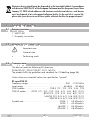
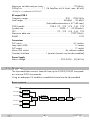
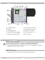
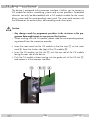
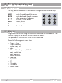
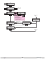
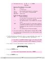
GSS GSS.mux SMCIP 401 is a transmodulator used for converting channels from a satellite signal into a digital signal that can be distributed via a cable network. It supports DVB-S and DVB-S2 satellite signals and can descramble channels using a Common Interface module. The device has four satellite inputs, a loop input for connecting an LNB, and one satellite output. It also has a micro USB socket for software updates and a Common Interface slot.
GSS GSS.mux SMCIP 401 is a transmodulator used for converting channels from a satellite signal into a digital signal that can be distributed via a cable network. It supports DVB-S and DVB-S2 satellite signals and can descramble channels using a Common Interface module. The device has four satellite inputs, a loop input for connecting an LNB, and one satellite output. It also has a micro USB socket for software updates and a Common Interface slot.


-
 1
1
-
 2
2
-
 3
3
-
 4
4
-
 5
5
-
 6
6
-
 7
7
-
 8
8
-
 9
9
-
 10
10
-
 11
11
-
 12
12
-
 13
13
-
 14
14
-
 15
15
-
 16
16
-
 17
17
-
 18
18
-
 19
19
-
 20
20
-
 21
21
-
 22
22
-
 23
23
-
 24
24
-
 25
25
-
 26
26
-
 27
27
-
 28
28
-
 29
29
-
 30
30
-
 31
31
-
 32
32
-
 33
33
-
 34
34
-
 35
35
-
 36
36


GSS GSS.mux SMCIP 401 Assembly Instructions Manual
- Type
- Assembly Instructions Manual
GSS GSS.mux SMCIP 401 is a transmodulator used for converting channels from a satellite signal into a digital signal that can be distributed via a cable network. It supports DVB-S and DVB-S2 satellite signals and can descramble channels using a Common Interface module. The device has four satellite inputs, a loop input for connecting an LNB, and one satellite output. It also has a micro USB socket for software updates and a Common Interface slot.
Ask a question and I''ll find the answer in the document
Finding information in a document is now easier with AI
Related papers
-
GSS SMCIP 401 ASI Assembly Instructions Manual
-
-
-
-
-
-
-
-
-
Other documents
-
König LNB-3X4 Datasheet
-
 TBS MOI+ User manual
-
Kathrein MSK 125 Operating instructions
-
Triax CGS-2 764 C Assembly Instructions Manual
-
KVH Industries TracVision M5 User manual
-
-
-
-
-
 HomeTech WBS41202NF User manual

