Chore-Time MA709G Models 55, 75, 90 & HMC Extension Hopper Installation and Operators Instruction Manual
- Type
- Installation and Operators Instruction Manual

Extension Hopper
Installation & Operator’s Instruction Manual
for
MA709G
July 2018
For additional parts and information, contact your nearest Chore-Time distributor or representative.
Find your nearest distributor at: www.choretime.com/contacts
Model 55, 75, 90, & HMC FLEX-AUGER
Feed Delivery Systems

2
Extension Hopper Instruction Manual
MA709G
Chore-Time Warranty
Chore-Time Group, a division of CTB, Inc. (“Chore-Time”) warrants new CHORE-TIME Cage and Cage
Components manufactured by Chore-Time to be free from defects in material or workmanship under normal usage
and conditions, for One (1) year from the date of installation by the original purchaser (“Warranty”). If such a defect
is determined by Chore-Time to exist within the applicable period, Chore-Time will, at its option, (a) repair the
Product or Component Part free of charge, F.O.B. the factory of manufacture or (b) replace the Product or
Component Part free of charge, F.O.B. the factory of manufacture. This Warranty is not transferable, and applies
only to the original purchaser of the Product.
CONDITIONS AND LIMITATIONS
THIS WARRANTY CONSTITUTES CHORE-TIME’S ENTIRE AND SOLE WARRANTY AND CHORE-TIME
EXPRESSLY DISCLAIMS ANY AND ALL OTHER WARRANTIES, INCLUDING, BUT NOT LIMITED TO,
EXPRESS AND IMPLIED WARRANTIES, INCLUDING, WIHTOUT LIMITATION, WARRANTIES AS TO
MERCHANTABILITY OR FITNESS FOR PARTICULAR PURPOSES. CHORE-TIME shall not be liable for any
direct, indirect, incidental, consequential or special damages which any purchaser may suffer or claim to suffer as a
result of any defect in the Product. Consequential or Special Damages as used herein include, but are not limited to,
lost or damaged products or goods, costs of transportation, lost sales, lost orders, lost income, increased overhead,
labor and incidental costs, and operational inefficiencies. Some jurisdictions prohibit limitations on implied
warranties and/or the exclusion or limitation of such damages, so these limitations and exclusions may not apply to
you. This warranty gives the original purchaser specific legal rights. You may also have other rights based upon your
specific jurisdiction.
Compliance with federal, state and local rules which apply to the location, installation and use of the Product are the
responsibility of the original purchaser, and CHORE-TIME shall not be liable for any damages which may result
from non-compliance with such rules.
The following circumstances shall render this Warranty void:
· Modifications made to the Product not specifically delineated in the Product manual.
· Product not installed and/or operated in accordance with the instructions published by the CHORE-TIME.
· All components of the Product are not original equipment supplied by CHORE-TIME.
· Product was not purchased from and/or installed by a CHORE-TIME authorized distributor or certified
representative.
· Product experienced malfunction or failure resulting from misuse, abuse, mismanagement, negligence,
alteration, accident, or lack of proper maintenance, or from lightning strikes, electrical power surges or
interruption of electricity.
· Product experienced corrosion, material deterioration and/or equipment malfunction caused by or consistent
with the application of chemicals, minerals, sediments or other foreign elements.
· Product was used for any purpose other than for the care of poultry and livestock.
The Warranty and Extended Warranty may only be modified in writing by an officer of CHORE-TIME. CHORE-
TIME shall have no obligation or responsibility for any representations or warranties made by or on behalf of any
distributor, dealer, agent or certified representative.
Effective: April, 2014

Table of Contents
Topic Page User*
*Legend: C = Customer (end user), D = Distributor (sales), I - Installer of equipment
MA709G
Chore-Time Warranty . . . . . . . . . . . . . . . . . . . . . . . . . . . . . . . . . . . . . . . . . . . . . . . . 2 C, D, I
Support Information . . . . . . . . . . . . . . . . . . . . . . . . . . . . . . . . . . . . . . . . . . . . . . . . . 4 C, D
Distributor and Installer Information . . . . . . . . . . . . . . . . . . . . . . . . . . . . . . . . . . . 4 C, D
Safety Information . . . . . . . . . . . . . . . . . . . . . . . . . . . . . . . . . . . . . . . . . . . . . . . . . . . 5 C, D, I
Safety–Alert Symbol. . . . . . . . . . . . . . . . . . . . . . . . . . . . . . . . . . . . . . . . . . . . . . . . . . . . . . .5
Signal Words. . . . . . . . . . . . . . . . . . . . . . . . . . . . . . . . . . . . . . . . . . . . . . . . . . . . . . . . . . . . .5
DANGER: Moving Auger . . . . . . . . . . . . . . . . . . . . . . . . . . . . . . . . . . . . . . . . . . . . . . . . . .5
DANGER: Electrical Hazard . . . . . . . . . . . . . . . . . . . . . . . . . . . . . . . . . . . . . . . . . . . . . . . .5
Notice of Caution . . . . . . . . . . . . . . . . . . . . . . . . . . . . . . . . . . . . . . . . . . . . . . . . . . . . 6 I
Introduction. . . . . . . . . . . . . . . . . . . . . . . . . . . . . . . . . . . . . . . . . . . . . . . . . . . . . . . . . 6C, I
Planning the Installation . . . . . . . . . . . . . . . . . . . . . . . . . . . . . . . . . . . . . . . . . . . . . . 7 C, I
Straight Line Application . . . . . . . . . . . . . . . . . . . . . . . . . . . . . . . . . . . . . . . . . . . . . . . . . . .7
Right Hand Turn Application . . . . . . . . . . . . . . . . . . . . . . . . . . . . . . . . . . . . . . . . . . . . . . . .8
Left Hand Turn Application . . . . . . . . . . . . . . . . . . . . . . . . . . . . . . . . . . . . . . . . . . . . . . . . .9
Installation Instructions . . . . . . . . . . . . . . . . . . . . . . . . . . . . . . . . . . . . . . . . . . . . . . . 10 I
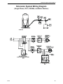
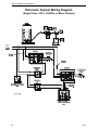
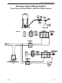
Extension System Wiring Diagram. . . . . . . . . . . . . . . . . . . . . . . . . . . . . . . . . . . . . . 11 C, I
(Single Phase, 230 V, 50/60Hz, w/o Motor Starters) . . . . . . . . . . . . . . . . . . . . . . . . . . . . . 11
(Single Phase, 230 V, 50/60Hz, w/ Motor Starters) . . . . . . . . . . . . . . . . . . . . . . . . . . . . . . 12
(Three Phase, 220/380/415/460 V, 50/60 Hz, w/ Motor Starters) . . . . . . . . . . . . . . . . . . . 13
Extension Hopper Parts Diagram . . . . . . . . . . . . . . . . . . . . . . . . . . . . . . . . . . . . . . . 14 C, I
Extension Hopper Parts Listing . . . . . . . . . . . . . . . . . . . . . . . . . . . . . . . . . . . . . . . . 15 C, I

Extension Hopper Instruction Manual
4
MA709G
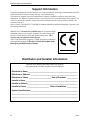
Support Information
Using this equipment for any other purpose or in a way not within the operating recommendations specified
in this manual will void the warranty and may cause personal injury.
This manual is designed to provide comprehensive planning, installation, operation, and parts listing
information. The Table of Contents provides a convenient overview of the information in this manual. The
Table of Contents also specifies which pages contain information for the sales personnel, installer, and
consumer (end user).
Refer to Chore-Time Model 55/75/90/HMC Installation Manual for additional installation, operation, and
parts listing information.
IMPORTANT: CE stands for certified Europe. It is a standard which
equipment must meet or exceed in ordered to be sold in Europe. CE
provides a benchmark for safety and manufacturing issues. CE is
required only on equipment sold in Europe.
Chore-Time Equipment recognizes CE Mark and pursues compliance
in all applicable products. Fill in the CE-Mark serial number in the
blank space provided for future reference.
Distributor and Installer Information
(CE-mark serial number)
Distributor’s Name ___________________________________________________
Distributor’s Address ________________________________________________
Distributor’s Phone _______________________ Date of Purchase ___________
Installer’s Name _____________________________________________________
Installer’s Address ___________________________________________________
Installer’s Phone _______________________ Date of Installation ___________
System Specifications ________________________________________________
___________________________________________________________________
___________________________________________________________________
Please fill in the following information about your Product.
Keep this manual in a clean, dry place for future reference.

Extension Hopper Instruction Manual
5
MA709G
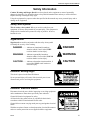
Safety Information
Caution, Warning and Danger Decals have been placed on the equipment to warn of potentially
dangerous situations. Care should be taken to keep this information intact and easy to read at all times.
Replace missing or damaged safety signs.
Using the equipment for purposes other than specified in this manual may cause personal injury and or
damage to the equipment.
Safety–Alert Symbol
This is a safety–alert symbol. When you see this symbol on your
equipment, be alert to the potential for personal injury. This equipment is
designed to be installed and operated as safely as possible...however,
hazards do exist.
Signal Words
Signal words are used in conjunction with the safety–alert symbol
to identify the severity of the warning.
DANGER........... indicates an imminently hazardous
situation which, if not avoided, WILL
result in death or serious injury.
WARNING........ indicates a potentially hazardous
situation which, if not avoided, COULD
result in death or serious injury.
CAUTION.......... indicates a hazardous situation which, if
not avoided, MAY result in minor or
moderate injury.
DANGER: Moving Auger
This decal is placed on the Panel Weldment.
Severe personal injury will result, if the electrical power is not
disconnected, prior to servicing the equipment.
DANGER: Electrical Hazard
Disconnect electrical power before inspecting or servicing equipment
unless maintenance instructions specifically state otherwise.
Ground all electrical equipment for safety.
All electrical wiring must be done by a qualified electrician in
accordance with local and national electric codes.
Ground all non-current carrying metal parts to guard against electrical
shock.
With the exception of motor overload protection, electrical disconnects
and over current protection are not supplied with the equipment.
DANGER
WARNING
CAUTION

Extension Hopper Instruction Manual
6
MA709G
Notice of Caution
Caution!
Use caution when working with the Auger—Springing auger may cause personal injury.
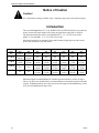
Introduction
The extended length Model 55, 75, 90, & HMC FLEX-AUGER Feed Delivery Systems are
used to increase the total length of the system in applications where this is required.
The Extension Boot Kits may be used with Model 55—1/3, 1/2 H.P. Power Units.
Model 75, 90, and HMC—1/2, 3/4, 1 H.P. Power Units.
Maximum lengths for the standard system and Extended Length Systems with various
power unit are shown in the chart below.
Maximum length recommendations for standard systems include use of two 45 degree
elbows. No elbows are included in the recommendations for maximum length of extension
systems. If additional elbows are required, decrease the length recommendations by 30 feet
(9 m) for each additional 90 degree turn.
Model 55 Model 75 Model 90 Model HMC
Motor
Size
Max.
Standard
Max.
Extension
Max.
Standard
Max.
Extension
Max.
Standard
Max.
Extension
Max.
Standard
Max.
Extension
1/3 H.P.
150 Feet
(46 M)
185 Feet
(56 M)
n//a n/a n/a n/a n/a n/a
1/2 H.P.
250 Feet
(76 M)
285 Feet
(87 M)
80 Feet
(24 M)
125 Feet
(38 M)
30 Feet
(9 M)
65 Feet
(20 M)
30 Feet
(9 M)
55 Feet
(17 M)
3/4 H.P.
n/a n/a
150 Feet
(46 M)
185 Feet
(56 M)
90 Feet
(27 M)
125 Feet
(38 M)
90 Feet
(27 M)
105 Feet
(32 M)
1 H.P.
n/a n/a
200 Feet
(61 M)
245 Feet
(75 M)
150 Feet
(46 M)
185 Feet
(56 M)
150 Feet
(46 M)
185 Feet
(56 M)

Extension Hopper Instruction Manual
7
MA709G
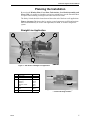
Planning the Installation
By moving the Window Plate, Cover Plate, Tube Anchor, Level Switch Assembly, and
Power Unit, it is possible to extend the system in a straight line or use the Extension Boot
to replace elbows making a 90 degree turn where that is convenient.
The Safety Switch should be located toward the outlet end of the boot on all applications.
Figures 1-6 (pages 7-9) shows that by moving several components to different locations
the Extension Boot may be used to turn right hand, left hand, or extend a straight line
system.
Straight Line Application
Key Description Part No.
1 Power Unit —
3 Level Switch Assembly 7840
4 Incoming Tube Anchor
Model 55
Model 75
Model 90, HMC
Seal
35531
6518
5069
4873
5 Cover Plate
Seal
4878
4873
6 Safety Switch Assembly 7840
Figure 2. Side View of a Straight Line Application
— arrows indicating feed flow
Figure 1. Side View of a Straight Line Application
MA709-10 8/97

Extension Hopper Instruction Manual
8
MA709G
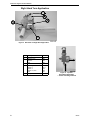
Right Hand Turn Application
Key Description Part No.
1 Power Unit —
2 Window Plate
Window
Seal
7842
7852
4873
3 Level Switch Assembly 7840
4 Incoming Tube Anchor
Model 55
Model 75
Model 90, HMC
Seal
35531
6518
5069
4873
6 Safety Switch Assembly 7840
Figure 4. Top View
Right Hand Application
— arrows indicating feed flow
Figure 3. Side View of a Right Hand Application

Extension Hopper Instruction Manual
9
MA709G
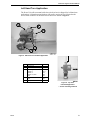
Left Hand Turn Application
The Power Unit will not mount beside the switch (as boot is shipped) for left hand turn
applications. Left hand turn applications will require moving the Level Switch to the
Access Plate location over the outlet end of the boot as shown in Figure 5.
Key Description Part No.
1 Power Unit —
3 Level Switch Assembly 7840
4 Incoming Tube Anchor
Model 55
Model 75
Model 90, HMC
Seal
35531
6518
5069
4873
5 Cover Plate
Seal
4878
4873
6 Safety Switch Assembly 7840
Figure 6. Top View
Left Hand Application
— arrows indicating feed flow
Figure 5. Side View of a Left Hand Application

Extension Hopper Instruction Manual
10
MA709G
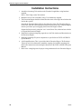
Installation Instructions
1. Attach the (incoming) Tube Anchor to the Extended Length Boot, using hardware
supplied.
Place a Tube Clamp on the Tube Anchor.
2. Mount the Power Unit on the Boot, using 5/16-18 hardware supplied.
3. The Extension Hopper should be located near the center of the auger line to balance the
load on the systems.
Suspend the Extension Hopper/Power Unit from the ceiling. The Extension Hopper,
Power Unit, and feed will weigh approximately 90 pounds (40.1 kg). Adequate support
must be provided to prevent sagging at the Extension Hopper location.
Support the Boot securely, using the “ears” on the Power Unit, chain and screw hooks
to suspend the Extension Hopper.
4. Install the incoming and outgoing auger tubes to the Tube Anchor and Boot Anchor on
the Extension Hopper.
5. Install the remaining fill system components as specified in the FLEX-AUGER Fill
System Manual .
6. A full length Restrictor Tube is provided with the Extension Hopper. The Restrictor
Tube may need to be shortened to match the outgoing feed with the incoming feed.
Refer to the instructions on shortening the Restrictor in the FLEX-AUGER Fill System
Manual .
7. Refer to the wiring diagrams for proper wiring information for the Extension Hopper.


Extension Hopper Instruction Manual
15
MA709G
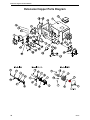
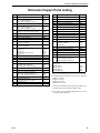
Extension Hopper Parts Listing
Key Description Part No.
1* Safety Cap (Model 75, 90, HMC) 29702
2 Tube Clamp Kit (Model 55)
Tube Clamp Kit (Model 75
Tube Clamp Kit (Model 90, HMC)
29520
4141
6721
3* 5/8” Set Collar 1386
4 Tube Clamp Kit (Model 55)
Tube Clamp Kit (Model 75)
Tube Clamp Kit (Model 90, HMC)
35726
6515
6721
5* Bearing Cap Assembly (Model 75)
Bearing Cap Assembly (Model 90, HMC)
35440
34830
6*** Cover Assembly 7839
7* Universal Anchor Shaft 43281
8* Clamp Spacer (Model 90) 5009
9* Clamp Pin (Model 75, 90, HMC) 4702
10* 5/16-18 x 1/2” Set Screw
(Model 75, 90, HMC)
5095
11* 5/16-18 x 3/8” Set Screw
(Model 75, 90, HMC)
1174
12* Anchor Weldment
(Model 55)
(Model 75
(Model HMC) Non Restricted
(Model 90)
39410
6840
36393
6833
13 Cover Plate 4878
14** Seal 4873
15 Switch and Plate Assembly 7840
16 Diaphragm Assembly 7900
17 Boot Body Weld. (Model 55)
Boot Body Weld. (Model 75)
Boot Body Weld. (Model 90, HMC)
40168
7878
28881
18 Window Plate 7842
19 Window 7852
20 Tube Anchor Weldment (Model 55)
Tube Anchor Weldment (Model 75)
Tube Anchor Weldment (Model 90, HMC))
35531
6518
5069
21 Access Panel Assembly 7928
22 Cannonball (Model 55)
Cannonball (Model 75, 90, HMC)
3621
3531
23** Switch Box Cover 6776
24** Gasket 6777
Description Part No.
25** Switch Box 7841
26** Switch Mounting Plate 7908
27** Paddle 7896
28** 6-32 x 7/8” Pan Hd. Screw 1921
29** Compression Spring 6972
30** SPDT Actuator Switch 7114
31** Switch Insulation 1907-5
32** Switch Bracket 7068
33** 1/8 x 1” Rd Hd Rivet 8757
34 5/16-18 X 1/2 Socket Hd Screw 6850-3
35 5/16-18 x 2-1/4 Socket Hd Screw 6850-4
36 Anchor Block 7703
37 Driver Weldment
(Model 75, HMC)
(Model 90)
7704
7706
*38 Auger Clamp (Model 55) 39205
*39 Anchor Bearing (Model 55) 39407
40 Cap (Model 55) 29523
41 Stub Tube (Model 55) 4163
*42 Socket Head Screw (Model 55) 6850-7
43 Tube Clamp Kit (Model 55)
Tube Clamp Kit (Model 75)
Tube Clamp Kit (Model 90)
29515
6515
6721
Part Numbers for Complete Extension
Hopper Kits
Model 55 Kit
Model 75 Kit
Model 90 Kit
Model HMC Kit
40170
7944
7869
7849
* These Anchor and Bearing components may be ordered as
an assembly under the following Chore-Time part numbers:
Model 55: #39405
Model 75: #37346
Model 90: #35343
Model HMC: #37241
** These Switch and Plate components may be ordered as an
assembly under Chore-Time part number #7840
*** The #7839 Cover Assembly includes items 14, 15, and
16 and the required hardware.

MA709G
MADE TO WORK.
BUILT TO LAST.
®
Revisions to this Manual
Page No. Description of Change ECO
14 Added updated Non-Restricted Anchor HMC Parts 33213
2 Updated Warranty
Contact your nearby Chore-Time distributor or representative for additional parts and information.
Chore-Time Group
A division of CTB, Inc.
PO Box 2000
Milford, Indiana 46542-2000 USA
Phone (574) 658-4101 Fax (877) 730-8825
E-mail: www.choretimepoultry.com
Internet: poultr[email protected]
Made to work.
Built to last.
TM
-
 1
1
-
 2
2
-
 3
3
-
 4
4
-
 5
5
-
 6
6
-
 7
7
-
 8
8
-
 9
9
-
 10
10
-
 11
11
-
 12
12
-
 13
13
-
 14
14
-
 15
15
-
 16
16


Chore-Time MA709G Models 55, 75, 90 & HMC Extension Hopper Installation and Operators Instruction Manual
- Type
- Installation and Operators Instruction Manual
Ask a question and I''ll find the answer in the document
Finding information in a document is now easier with AI
Related papers
-
 Chore-Time MA709E Models 55, 75, 90 & HMC Extension Hopper Installation and Operators Instruction Manual
-
 Chore-Time MA773F Circulating Feed Delivery System Installation and Operators Instruction Manual
-
 Chore-Time MA773G Circulating Feed Delivery System Installation and Operators Instruction Manual
-
 Chore-Time MA2485C Twin Stackable Control Unit Installation and Operators Instruction Manual
-
 Chore-Time MA2485A Twin Stackable Control Unit Installation and Operators Instruction Manual
-
 Chore-Time MA2485B Twin Stackable Control Unit Installation and Operators Instruction Manual
-
 Chore-Time MA1000G Model 55, 75, 90 HMC FLEX-AUGER® Installation and Operators Instruction Manual
-
 Chore-Time MA1712A Feed Screener Model 90 & 108 Single & Dual Installation and Operators Instruction Manual
-
 Chore-Time MA524F 30-Degree Two Motor Tandem Installation and Operators Instruction Manual
-
 Chore-Time MA1712B Feed Screener Model 90 & 108 Single & Dual Installation and Operators Instruction Manual


