Page is loading ...

Installation and Operation Manual
X-SW-DDE-MFC-eng
Part Number 541C057AAG
January, 2013
Smart DDE Software
Smart DDE Software
for use with Brooks Digital Mass Flow Meter/Controller Series

Installation and Operation Manual
X-SW-DDE-MFC-eng
Part Number 541C057AAG
January, 2013
Smart DDE Software
ESD (Electrostatic Discharge)
CAUTION: This instrument contains electronic components that are susceptible to damage by static electricity. Proper handling procedures
must be observed during the removal, installation or other handling of internal circuit boards or devices.
Handling Procedure:
1. Power to unit must be removed.
2. Personnel must be grounded, via a wrist strap or other safe, suitable means before any printed circuit card or other internal device is installed,
removed or adjusted.
3. Printed circuit cards must be transported in a conductive container. Boards must not be removed from protective enclosure until immediately before
installation. Removed boards must immediately be placed in protective container for transport, storage or return to factory.
Comments
This instrument is not unique in its content of ESD (electrostatic discharge) sensitive components. Most modern electronic designs contain components
that utilize metal oxide technology (NMOS, SMOS, etc.). Experience has proven that even small amounts of static electricity can damage or destroy these
devices. Damaged components, even though they appear to function properly, exhibit early failure.
Brooks Instrument designs, manufactures and tests its products to meet many national and international standards. These products must be properly
installed, operated and maintained to ensure they continue to operate within their normal specifications. The following instructions must be adhered to
and integrated into your safety program when installing, operating and maintaining Brooks Instrument products.
• To ensure proper performance, use qualified personnel to install, operate, update, program and maintain the product.
• Read all instructions prior to installing, operating and servicing the product. If this instruction manual is not the correct manual, please see back cover
for local sales office contact information. Save this instruction manual for future reference.
WARNING: Do not operate this instrument in excess of the specifications listed in the Instruction and Operation Manual. Failure to heed
this warning can result in serious personal injury and / or damage to the equipment.
• If you do not understand any of the instructions, contact your Brooks Instrument representative for clarification.
• Follow all warnings, cautions and instructions marked on and supplied with the product.
• Install your equipment as specified in the installation instructions of the appropriate instruction manual and per applicable local and national codes.
Connect all products to the proper electrical and pressure sources.
• Operation: (1) Slowly initiate flow into the system. Open process valves slowly to avoid flow surges. (2) Check for leaks around the flow meter inlet
and outlet connections. If no leaks are present, bring the system up to the operating pressure.
• Please make sure that the process line pressure is removed prior to service. When replacement parts are required, ensure that qualified people use
replacement parts specified by Brooks Instrument. Unauthorized parts and procedures can affect the product's performance and place the safe
operation of your process at risk. Look-alike substitutions may result in fire, electrical hazards or improper operation.
• Ensure that all equipment doors are closed and protective covers are in place to prevent electrical shock and personal injury, except when
maintenance is being performed by qualified persons.
WARNING: For liquid flow devices, if the inlet and outlet valves adjacent to the devices are to be closed for any reason, the devices must
be completely drained. Failure to do so may result in thermal expansion of the liquid that can rupture the device and may cause personal
injury.
All pressure equipment with an internal pressure greater than 0.5 bar (g) and a size larger than 25mm or 1" (inch) falls under the Pressure Equipment Directive
(PED).
• The Specifications Section of this manual contains instructions related to the PED directive.
• Meters described in this manual are in compliance with EN directive 97/23/EC.
• All Brooks Instrument Flowmeters fall under fluid group 1.
• Meters larger than 25mm or 1" (inch) are in compliance with PED category I, II or III.
• Meters of 25mm or 1" (inch) or smaller are Sound Engineering Practice (SEP).
The Brooks Instrument (electric/electronic) equipment bearing the CE mark has been successfully tested to the regulations of the Electro
Magnetic Compatibility (2004/108/EC (EMC directive 89/336/EEC)).
Special attention however is required when selecting the signal cable to be used with CE marked equipment.
Quality of the signal cable, cable glands and connectors:
Brooks Instrument supplies high quality cable(s) which meets the specifications for CE certification.
If you provide your own signal cable you should use a cable which is overall completely screened with a 100% shield.
“D” or “Circular” type connectors used should be shielded with a metal shield. If applicable, metal cable glands must be used providing cable
screen clamping.
The cable screen should be connected to the metal shell or gland and shielded at both ends over 360 Degrees.
The shield should be terminated to an earth ground.
Card Edge Connectors are standard non-metallic. The cables used must be screened with 100% shield to comply with CE certification.
The shield should be terminated to an earth ground.
For pin configuration : Please refer to the enclosed Instruction Manual.
European Pressure Equipment Directive (PED)
European Electromagnetic Compatibility (EMC)
Essential Instructions
Read before proceeding!

Installation and Operation Manual
X-SW-DDE-MFC-eng
Part Number 541C057AAG
January, 2013
Smart DDE Software
Dear Customer,
We appreciate this opportunity to service your flow measurement and control requirements with a Brooks
Instrument device. Every day, flow customers all over the world turn to Brooks Instrument for solutions to their
gas and liquid low-flow applications. Brooks provides an array of flow measurement and control products for
various industries from biopharmaceuticals, oil and gas, fuel cell research and chemicals, to medical devices,
analytical instrumentation, semiconductor manufacturing, and more.
The Brooks product you have just received is of the highest quality available, offering superior performance,
reliability and value to the user. It is designed with the ever changing process conditions, accuracy requirements
and hostile process environments in mind to provide you with a lifetime of dependable service.
We recommend that you read this manual in its entirety. Should you require any additional information concerning
Brooks products and services, please contact your local Brooks Sales and Service Office listed on the back cover
of this manual or visit www.BrooksInstrument.com
Yours sincerely,
Brooks Instrument

Installation and Operation Manual
X-SW-DDE-MFC-eng
Part Number 541C057AAG
January, 2013
Smart DDE Software
THIS PAGE WAS
INTENTIONALLY
LEFT BLANK

Installation and Operation Manual
X-SW-DDE-MFC-eng
Part Number 541C057AAG
January, 2013 Smart DDE Software
I
Contents
Section Page
Number Number
Section 1 Introduction
1.1 General Information ................................................................................................................................ 1-1
1.2 Use of Smart DDE .................................................................................................................................. 1-1
Section 2 Getting Started
2.1 Introduction ............................................................................................................................................. 2-1
2.2 System Requirements............................................................................................................................. 2-1
2.3 Supported Brooks Devices ..................................................................................................................... 2-1
2.4 Interconnection Configurations ............................................................................................................... 2-1
2.4.1 Digital Mass Flow Products .............................................................................................................. 2-1
2.4.2 Secondary Electronics ...................................................................................................................... 2-3
2.5 Concept of DDE...................................................................................................................................... 2-4
2.6 Installing Smart DDE............................................................................................................................... 2-5
2.7 Running Smart DDE ............................................................................................................................... 2-6
Section 3 Smart DDE User Interface
3.1 Introduction ............................................................................................................................................. 3-1
3.2 Main Window .......................................................................................................................................... 3-1
3.2.1 Communication Ports ....................................................................................................................... 3-2
3.2.2 DMFC's ............................................................................................................................................ 3-2
3.2.3 Conversations .................................................................................................................................. 3-2
3.2.4 Advise Links ..................................................................................................................................... 3-3
3.2.5 Status Bar......................................................................................................................................... 3-3
3.3 Control .................................................................................................................................................... 3-4
3.3.1 Opening a Communication Port........................................................................................................ 3-4
3.3.2 Closing a Communication Port ......................................................................................................... 3-6
3.3.3 Opening a New DMFC ..................................................................................................................... 3-7
3.3.4 Opening an existing DMFC............................................................................................................... 3-8
3.3.5 Closing a DMFC ............................................................................................................................... 3-9
3.3.6 Copying DDE-Link Information ........................................................................................................ 3-10
3.3.7 Exit Smart DDE ............................................................................................................................... 3-10
3.4 DMFC .................................................................................................................................................... 3-11
3.4.1 Write Protection............................................................................................................................... 3-11
3.4.2 Changing the Password .................................................................................................................. 3-12
3.4.3 Backing Up to EEPROM.................................................................................................................. 3-12
3.4.4 Restore from EEPROM ................................................................................................................... 3-13
3.4.5 Read from DMFC ............................................................................................................................
3-13
3.4.6 Read from File................................................................................................................................. 3-14
3.4.7 Write to File ..................................................................................................................................... 3-14
3.5 Device Data ........................................................................................................................................... 3-14
3.5.1 Actual Data ...................................................................................................................................... 3-16
3.5.2 General Data ................................................................................................................................... 3-17
3.5.3 Mechanical Data.............................................................................................................................. 3-18
3.5.4 Gas Data ......................................................................................................................................... 3-19
3.5.5 Sensor Data .................................................................................................................................... 3-20
3.5.6 General Settings.............................................................................................................................. 3-21
3.5.7 I/O Settings...................................................................................................................................... 3-22
3.5.8 Controller Settings ........................................................................................................................... 3-24
3.6 Preference ............................................................................................................................................. 3-25
3.6.1 Refresh Rate ................................................................................................................................... 3-26

Installation and Operation Manual
X-SW-DDE-MFC-eng
Part Number 541C057AAG
January, 2013Smart DDE Software
II
Contents
Section Page
Number Number
3.6.2 Communication Settings.................................................................................................................. 3-26
3.7 Main Window Pop Up Menus................................................................................................................. 3-27
3.7.1 Communication Pop Up Menu......................................................................................................... 3-27
3.7.2 DMFC Pop Up Menu ....................................................................................................................... 3-28
3.7.3 Advise Pop Up Menu ....................................................................................................................... 3-29
Section 4 Smart DDE Link Basics
4.1 Smart DDE Conversation Principles ....................................................................................................... 4-1
4.1.1 Service names.................................................................................................................................. 4-3
4.1.2 Topic Names .................................................................................................................................... 4-4
4.1.3 Items Names .................................................................................................................................... 4-6
4.2 Tag Number Related Server Requests.................................................................................................... 4-7
4.2.1 Request ............................................................................................................................................ 4-7
4.2.2 Advise............................................................................................................................................... 4-8
4.2.3 Poke ................................................................................................................................................. 4-9
4.2.4 Execute ........................................................................................................................................... 4-10
4.3 Data Formatting...................................................................................................................................... 4-12
4.4 Setting Up a Conversation Link.............................................................................................................. 4-13
Section 5 Advanced Smart DDE Topics
5.1 Item Status.............................................................................................................................................. 5-1
5.2 Command Line Parameters .................................................................................................................... 5-3
5.3 Starting Smart DDE From Out of Another Windows Application .............................................................. 5-3
5.4 Setting Up A Connection Using a DMF-File............................................................................................. 5-3
5.5 Copying a Link Using the Clipboard ........................................................................................................ 5-4
5.6 Changing Advise Link Items.................................................................................................................... 5-7
5.7 Related DMFC Parameters..................................................................................................................... 5-7
5.8 WIN.INI Settings...................................................................................................................................... 5-8
Section 6 Smart DDE Troubleshooting
6.1 Introduction ............................................................................................................................................. 6-1
6.2 General Problems................................................................................................................................... 6-1
6.3 Application Crash .................................................................................................................................... 6-4
Appendix A: Item List ..................................................................................................................................... A-1
Appendix B: Execute Commands ................................................................................................................. B-1
Appendix C: DMFC
Alarm Troubleshooting .................................................................................................C-1
Appendix D Anolog I/O Calibration ...............................................................................................................D-1
D.1 Calibrating the Analog Setpoint Input ......................................................................................................D-1
D.2 Calibrating the Analog Flow Outputs .......................................................................................................D-2
Index ................................................................................................................................................................ i-i
Warranty, Local Sales/Service Contact Information ....................................................................... Back Cover
Figures

Installation and Operation Manual
X-SW-DDE-MFC-eng
Part Number 541C057AAG
January, 2013 Smart DDE Software
III
Contents
Figure Page
Number Number
2.1 RS-232 Interconnection with DMFC and PC ........................................................................................... 2-2
2.2 Multidrop Interconnection DMFC's and PC ............................................................................................. 2-2
3.1 Smart DDE Main Window ....................................................................................................................... 3-1
3.2 The Control Menu ................................................................................................................................... 3-4
3.3 Open Communication Port Window ........................................................................................................ 3-4
3.4 Open Communication Port Window for 0152/54 ..................................................................................... 3-5
3.5 Open Communication Port Window for 0254 .......................................................................................... 3-6
3.6 Open a New DMFC Window................................................................................................................... 3-7
3.7 Open a New DMFC Window for 0152/54 Read Out................................................................................ 3-8
3.8 Open a New DMFC Window for 0254 Read Out..................................................................................... 3-8
3.9 Main Window Showing the Tag Number of a 0254 Read Out .................................................................. 3-8
3.10 The DMFC Window ............................................................................................................................... 3-9
3.11 Exit Conformation Window ................................................................................................................... 3-10
3.12 The DMFC Menu.................................................................................................................................. 3-11
3.13 Write Protect Window........................................................................................................................... 3-11
3.14 Change Password Window ................................................................................................................. 3-12
3.15 The Device Data Menu ......................................................................................................................... 3-15
3.16 Actual Data Window ............................................................................................................................. 3-16
3.17 General Data Window .......................................................................................................................... 3-17
3.18 Mechanical Data Window ..................................................................................................................... 3-18
3.19 Gas Data Window ................................................................................................................................ 3-19
3.20 Sensor Data Window............................................................................................................................ 3-20
3.21 General Settings Window ..................................................................................................................... 3-21
3.22 I/O Settings Window............................................................................................................................. 3-22
3.23 Controller Settings Window .................................................................................................................. 3-24
3.24 Refresh Rate Selection......................................................................................................................... 3-26
3.25 Communication Settings Window......................................................................................................... 3-27
3.26 The Communication Pop Up Menu....................................................................................................... 3-28
3.27 The DMFC Pop Up Menu ..................................................................................................................... 3-28
3.28 The Advise Link Pop Up Menu ............................................................................................................. 3-29
4.1 Three-Level Conversion Identification Hierarchy ..................................................................................... 4-3
5.1 Select the Desired Item Using the Actual Data Window .......................................................................... 5-5
5.2 Microsoft Excel 5.0 Paste Special Window.............................................................................................. 5-6
5.3 Microsoft Excel 5.0 Displaying the Actual Measured Flow from the DMFC.............................................. 5-6
Tables
Table Page
Number Number
2.1 D-Connector Communication Pins.......................................................................................................... 2-2
5.1 Item Status Bytes .................................................................................................................................... 5-1
6.1 General Troubleshooting......................................................................................................................... 6-1
6.2 DDE Link Troubleshooting ...................................................................................................................... 6-2
6.3 DMFC Troubleshooting ........................................................................................................................... 6-3
A.1 Item List System Parameters..................................................................................................................A-1
A.2 Item List Configuration Parameters.........................................................................................................A-2

Installation and Operation Manual
X-SW-DDE-MFC-eng
Part Number 541C057AAG
January, 2013Smart DDE Software
IV
Contents
Tables
Table Page
Number Number
A.3 Item List Calibration Parameters.............................................................................................................A-2
A.4 Item List Gas Parameters ....................................................................................................................... A-3
A.5 Item Numbers Gas Parameters .............................................................................................................. A-4
A.6 Item List Sensor Parameters ..................................................................................................................A-4
A.7 Item List Operation Parameters .............................................................................................................. A-5
A.8 Item List Controller Parameters .............................................................................................................. A-5
A.9 Item List Actual Parameters.................................................................................................................... A-6
A.10 Item List Additional DMFC Revision E Parameters ............................................................................... A-6
A.11 Device Type Codes ...............................................................................................................................A-7
A.12 Materials Codes ....................................................................................................................................A-7
A.13 Density Unit Codes ...............................................................................................................................A-7
A.14 Flow Unit Codes....................................................................................................................................A-8
A.15 Temperature Unit Codes ....................................................................................................................... A-8
A.16 Pressure Unit Codes............................................................................................................................. A-8
A.17 Flow Reference Codes.......................................................................................................................... A-8
A.18 Setpoint Source Codes ......................................................................................................................... A-9
A.19 Softstart Selection Codes......................................................................................................................A-9
A.20 Pressure Reference Codes...................................................................................................................A-9
A.21 Valve Override Codes ...........................................................................................................................A-9
A.22 Analog Range Codes ............................................................................................................................ A-9
A.23 Valve Type Codes .................................................................................................................................A-9
A.24 Adaptive Control Codes.........................................................................................................................A-9
A.25 Totalizer Function Codes...................................................................................................................... A-10
A.26 Totalizer Unit Codes ............................................................................................................................. A-10
A.27-1 Additional Device Status and Masking for 58xxS and MfxxS Models ................................................ A-10
A.27-2 Additional Device Status and Masking for SLA58xxS and SLAMfxxS Models ................................... A-11
A.27-3 Additional Device Status and Masking for 48xxS Models .................................................................. A-12
A.28 Orifice Size Codes ............................................................................................................................... A-13
A.29 Supported DDE Items per Device Type................................................................................................ A-14
A.30 Execute Commands............................................................................................................................. A-23
B.1 Execute Requests................................................................................................................................... B-1
C.1 Troubleshooting Fatal Alarms ................................................................................................................. C-1
C.2 Troubleshooting Non-Fatal Alarms..........................................................................................................C-2
C.3 Troubleshooting Additional Non-Fatal Alarms..........................................................................................C-3

1-1
Section 1 Introduction
Installation and Operation Manual
X-SW-DDE-MFC-eng
Part Number 541C057AAG
January, 2013
Smart DDE Software
1.1 General Information
Brooks Smart DDE software for Microsoft
®
Windows™ is a server
application, making it easy to communicate with the Brooks Digital Mass
Flow Meters/Controllers Models GF40/GF80, 48xxS, SLA58xxS,
SLAMfxxS, 58xxS, & MfxxS, as well as the 0152/54 and 0254 secondary
electronics devices through other Windows applications which support
Dynamic Data Exchange (DDE). This enables you to communicate with
one or more Brooks Digital Mass Flow Meters or Controllers, using
common available Windows client applications (e.g. Microsoft Excel).
Smart DDE is designed to allow you to access the configuration data in the
models, take measurement data from the models and — in case of the
Mass Flow Controllers — send setpoint values, by using the Windows
Dynamic Data Exchange facilities. The protocol used for the
communication between the Mass Flow Meters and Controllers and the
Smart DDE software is based on the Emerson HART™ protocol and can
take place over either RS-232 or RS-485 (The Bell-202 as normally used
with the true HART is NOT supported within the S-series).
Note that the GF40/GF80, 48xx and SLA device families only support the
RS-485 interface, the 58xxS and MfxxS devices support both the RS-232
and RS-485 interfaces. The 0152/54 and 0254 secondary elctronics
devices only support the RS-232 interface.
This manual explains how to use Smart DDE, in combination with other
programs which support DDE, under the Microsoft Windows environment
for PCs personal computers in conjunction with the Brooks Digital Mass
Flow products.
The manual does not cover the functionality of the Brooks Mass Flow
Meters and Controllers itself. These products are described in detail;
please refer to the specific instruction manual for your device. For detailed
protocol message structure refer to the Communication Instruction manual;
Document 541-C-053-AAA.
NOTE: The reader is assumed to have knowledge on how to use the Microsoft
Windows environment for PCs (personal computers).
1-2 Use of Smart DDE
The Brooks Digital Mass Flow products are equipped with analogue I/O,
representing the mass flow and —in case of a controller— the setpoint.
The information on these I/O ports are represented as a voltage signal
ranging from 0 (1) to 5 Volt or as a current signal ranging from 0 (4) to 20
mA.
In addition, all models can be equipped with a communication piggyback
board, providing access to the flow and setpoint information, either in a
range from 0% to 100%, or in selectable engineering units. You also have
access to the configuration parameters of the device.

1-2
Section 1 Introduction
Installation and Operation Manual
X-SW-DDE-MFC-eng
Part Number 541C057AAG
January, 2013
Smart DDE Software
Smart DDE gives you the opportunity to communicate with one or more
devices (equipped with communication piggyback board), which are
hooked up to the host computer through a point to point or a multidrop
network connection, using a personal computer with regular software, e.g.
Excel or Word. Smart DDE enables other applications to perform tasks
like:
- Visualising on line measurement data
- Control process settings
- Inspect or change configuration data
- Configuring operational settings
- Optimise the control parameters of the device for your process
application
- Monitoring the process for diagnostic alarm conditions
- Communicate with a device from a remote computer using the
Windows for Workgroups network DDE facilities.
With Smart DDE it is possible to make your own applications for
communication with your device using data acquisition programs like
LabVIEW
®
or Testpoint™, or SCADA programs like FIX DMACS™, without
concerning about the details of the HART protocol. Also typical Windows
programming languages like C(++), Pascal or even 4GL’s work just fine
with Smart DDE as the DDE server.
Smart DDE offers you the possibility to integrate Brooks Digital Mass Flow
products in your own process control application.

2-1
Section 2 Getting Started
Installation and Operation Manual
X-SW-DDE-MFC-eng
Part Number 541C057AAG
January, 2013 Smart DDE Software
2.1 Introduction
This section will deal with the installation of the Smart DDE software and
setting up your system in order to establish communication with the Brooks
Digital Mass Flow products. The system requirements will be discussed as
well as the hardware connections which must be made between the
device(s) and the host computer.
In addition, some basics about Dynamic Data Exchange are explained
before the instruction on how to install the software. See the following
sections for a more detailed description on how to use the program and
making links between Smart DDE and other programs.
2.2 System Requirements
When using Smart DDE with RS-485, an additional RS-232 to RS-485
converter or RS-485 interface board is required. Smart DDE supports
automatic and manual switching converters.
IMPORTANT NOTE: To support a wide range of RS-232 to RS-485
converters and RS-485 interface boards, Smart DDE allows the selection
of both the direction control line (i.e. RTS or DTR) and the read- and write
buffer logical levels (i.e. logical ‘1’ activating the write buffer and logical ‘0’
activating the read buffer, or logical ‘0’ activating the write buffer and logical
‘1’ activating the read buffer). Contact Brooks Instrument for available
converters and interface boards.
Smart DDE is designed for the following platforms/operating systems:
1. Microsoft Windows 98 (SE)
2. Microsoft Windows 2000 (With SP4)
3. Microsoft Windows XP (With SP2)
4. Microsoft Windows Vista
2.3 Supported Brooks Devices
Models GF40/GF80, 48xxS, SLA58xxS, SLAMfxxS, 58xxS, MfxxS, 0152/
54 and 0254 are supported. Refer to the instruction manuals available at
the Brooks website (www.BrooksInstrument.com) Documentation &
Downloads/Product Documentation link “Thermal Mass Flow Meters &
Controllers, Digital, Gas” and/or "Secondary Electronics (Power Supplies &
TMF Accessories)".
2.4 Interconnection Configurations
Models 58xxS and MfxxS both support RS-232 and RS-485 interface
whereas Models GF40/GF80, 48xxS SLA58xxS and SLAMfxxS only
support the RS-485 interface. The 0152/54 and 0254 secondary
electronics devices only support the RS-232 interface.
2.4 .1 Digital Mass Flow Products
The RS-232 is essentially a point-to-point connection, i.e. one host
computer and one Digital Mass Flow Meter/Controller model. The standard
cable supplied by Brooks (part number 124Z893ZZZ, 124Z894ZZZ or
124Z895ZZZ) is a split cable, suited for RS-232 communication: the
communication part of the cable can directly be connected to the serial
COM-port of any PC or PC with USB to RS-232 converter. The other part
of the cable can be connected to the Brooks Model 0152/0154 or 0154

2-2
Section 2 Getting Started
Installation and Operation Manual
X-SW-DDE-MFC-eng
Part Number 541C057AAG
January, 2013Smart DDE Software
D-connector
pin number
RS-232
RS-485
Pin #9 Ground Not Used
Pin #14 Receiver Input A-
Pin #15 Transmitter Output A+
Table 2.1 D-Connector Communication Pins
3(2)
2(3)
7(5)
D-connector to DTE:
25-pin (9-pin)
DTE
RxD
TxD
Gnd
RTS or DTR
4(7) or 20(4)
120
A+ A-
1
9 15
8
A+ A-
1
9
15
8
RS-485RS-232
converte
r
120
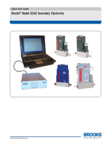
Figure 2.2 Multidrop Interconnection with DMFC's and PC
Important Note: When you provide your own cable assembly,
please refer to Brooks Documents 541-C-051 AAG (Elastomer Seal) or
(Metal Seal/UHP) Document Number 541-C-067.
secondary electronics. These models provide power to the Digital Mass
Flow Meter and Controller models and perform local read out and display
of the analog output signals. Figure 2.1 shows the interconnection diagram
of the RS-232 configuration. The pin assignment on the DTE (Data
Terminal Equipment), which represents the PC, is standard for RS-232.
Figure 2.1 RS-232 Interconnection with DMFC and PC
DTE
RxD
TxD
Gnd
3(2)
2(3)
7(5)
1
9
8
D-connector to DTE
25-pin (9-pin)
15

2-3
Section 2 Getting Started
Installation and Operation Manual
X-SW-DDE-MFC-eng
Part Number 541C057AAG
January, 2013 Smart DDE Software
The Break out cable with part number S-124-Z-905-ZZZ can be used if the
device is already connected via a power cable. The power cable needs to
be disconnected and can be reconnected once the break out cable is
connected onto the device.
The RS-485 is essentially a multidrop connection. It allows connection of
max. 32 devices to a computer system. PC’s are not standard equipped
with RS-485 ports, thus requiring a RS-232 to RS-485 or USB to RS-485
convertor. Figure 2.2 shows the interconnection diagram of two DMFC’s,
via RS-485 and a RS-485 to RS-232 converter, to a PC. The RS-485 bus
requires two matching resistors of 120 Ohm, one at the end of the bus and
one at the beginning, near (or sometimes already in) the converter.
NOTE: In a RS-485 connection some converters require a control line from
the PC to the converter in order to control the data direction of the RS-485
buffers. To support a wide range of RS-232 to RS-485 converters, Smart
DDE makes it possible to select both the direction control line (i.e. RTS or
DTR) and the read- and write buffer logical levels (i.e. logical ‘1’ activating
the write buffer and logical ‘0’ activating the read buffer, or logical ‘0’
activating the write buffer and logical ‘1’ activating the read buffer). Many
RS-232/RS-485 converters are automatically switching and do not require
a switch line.
2.4.2 Secondary Electronics
In addition to digital mass flow products, the Smart DDE application also
works with the Models 0152/54 and 0254 secondary electronics. An RS-
232 cable is needed for communication. This cable needs to be connected
between the RS-232 port on the secondary electronics and the serial-com
port of the PC or PC with USB to RS-232 converter. Note that the
communication cable is specific for each model. Refer to the specific
secondary electronics instruction manuals for details. The instruction
manuals are available at the Brooks website (www.BrooksInstrument.com)
Documentation & Product Documentation "Secondary Electronics (Power
Supplies & TMF Accessories)".

2-4
Section 2 Getting Started
Installation and Operation Manual
X-SW-DDE-MFC-eng
Part Number 541C057AAG
January, 2013Smart DDE Software
2.5 Concept of DDE
Smart DDE offers all the functions you need to access the information from
the Brooks Digital Mass Flow Controller/Meter. Dynamic Data Exchange
(DDE) is a form of communication using shared memory in order to
exchange data between application programs. Applications can use DDE
for one-time data transfers and for ongoing exchanges in which the
programs send updates to one another as new data becomes available.
Dynamic Data Exchange differs from the clipboard data-transfer
mechanism which is also part of the Windows operating system. One
difference is that the clipboard is used as a one-time response to a specific
action by the user—such as choosing the Cut/Paste command from a
menu. Although DDE may also be initiated by a user, it typically continues
without the user’s further involvement.
The principles of Dynamic Data Exchange are based on a conversation
between two applications, a client and a server:
Client The application requesting information or initiating an action.
Server The application providing the information requested by the client
or executing an action (i.e. Smart DDE).
A client requests the server to provide a service. There are several
types of server requests:
Request The client asks the server for a single piece of information
(‘cold’ link)
Advise (special request) A continuous form of information transfer from
the server to the client, initiated by the client (‘hot’/’warm’ link).
Poke The client asks the server to change a data item and therefor
sends the information to the server.
Execute The server is asked by the client to execute a command.
A conversation service is set up by the client application using the three-
level hierarchy of service, topic and item names. Each service is uniquely
identified by the service name and the topic name, which can not be
changed during the existence of the conversation. The information,
exchanged within a conversation between two applications, is identified
with the usage of item names. It is possible to transfer several different
items using the same conversation.

2-5
Section 2 Getting Started
Installation and Operation Manual
X-SW-DDE-MFC-eng
Part Number 541C057AAG
January, 2013 Smart DDE Software
2.6 Installing Smart DDE
The Smart DDE software is available on the Smart CD part number 535-F-
002 and on the Smart DDE CD part number 535-F-003.
Both the Smart CD and the Smart DDE CD are programmed with the auto
run feature, which means that the installation menu should be shown
automatically after inserting the CD. If this doesn’t happen, the executable
in the root of the CD folder structure should be started manually, e.g. select
the ‘Browse’ button in the ‘Start->Run’ window, navigate to the root of the
CD folder and select the executable.
Select Smart DDE in the menu, at the right side of the installation window a
radio button will be shown indicating Smart DDE, which needs to be
selected prior to activating the install button.
The install wizard will show a welcome screen once the install button is
activated. After clicking the next button the user has to select the ‘I accept
the terms in the license agreement’ radio button and click the next button.
In the last screen the user is given the option to launch Smart DDE after
the installation is finished.
Once the installation is finished, the Smart DDE application can be started
via the ‘Start->All Programs->Brooks Instrument->Smart DDE->Smart
DDE’ menu option.

2-6
Section 2 Getting Started
Installation and Operation Manual
X-SW-DDE-MFC-eng
Part Number 541C057AAG
January, 2013Smart DDE Software
2.7 Running Smart DDE
Smart DDE is a translation program (driver), which translates the HART
based communication protocol, used to communicate with one or more
Brooks Digital Mass Flow Meters/Controllers, to the Windows Dynamic
Data Exchange mechanism. Because Smart DDE is a DDE-driver for other
applications, the program is not useful as a stand-alone program, i.e. it will
not show you the DMFC data.
To perform the function as DDE-driver, Smart DDE needs to be active
(mostly running in background) in combination with your application. To get
Smart DDE running, there are two possibilities:
1. Start Smart DDE from the Program Manager and setup one or more
DMFC-connections using the Smart DDE user interface (refer to
section 3).
2. Start Smart DDE and setup the DMFC-connections from your own
application without intervention of the Smart DDE user interface (refer
to section 5)

3-1
Section 3 Smart DDE User Interface
Installation and Operation Manual
X-SW-DDE-MFC-eng
Part Number 541C057AAG
January, 2013 Smart DDE Software
3.1 Introduction
The Smart DDE must be considered as a communication interface
between the Digital Mass Flow Controller/Meter and other applications
supporting DDE and is of no use as stand alone application. Most of the
time the Smart DDE program operates in the background, serving other
applications. Therefor, all functions within Smart DDE, necessary for
setting up, maintaining and changing DDE-links can be called from a client
application using the DDE mechanism.
The Smart DDE user interface provides you several utilities, for example
manually setting up communication links, visualizing existing conversation
links and showing error messages. This section explains the functions of
the Smart DDE user interface.
3.2 Main Window
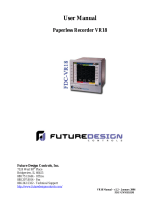
Figure 3.1 shows an example of the main window of Smart DDE with
several communication links established between DMFC’s and other
applications.
Figure 3.1 Smart DDE Main Window
The main window shows the status of all links with other resources in
Windows, using the following icons:
1. COM (Yellow)Communication ports
2. Tag (Red) DMFC’s
3. Conv (Green)Conversations with client applications
4. Item (Blue) Advise links
NOTE: The icons can take three different shapes which reflect the
hierarchical structure; the , the and the . The last shape indicates
the end of a branch in the hierarchical tree. You can toggle between the
and the . Just double click with the left mouse button on the involved
line. This allows you to show/hide portions of the hierarchical tree.

3-2
Section 3 Smart DDE User Interface
Installation and Operation Manual
X-SW-DDE-MFC-eng
Part Number 541C057AAG
January, 2013Smart DDE Software
The bottom row displays a status bar showing information on the status of
the communication links.
3.2.1 Communications Ports
‘ COM’ icons indicate open communication ports along with their
matching communication settings.
EXAMPLE: Figure 3.1 shows one open communication port, i.e. COM1
which is configured to RS-232.
NOTE: Communication ports used by Smart DDE (all communication ports
displayed in the main window) are exclusively in use by Smart DDE and
can not be accessed by other applications.
3.2.2 DMFC's
‘
Tag’ icons indicate open Digital Mass Flow Controllers/Meters (DMFC)
or Secondary Electronics (SE). The information behind the icon shows the
tag number of the DMFC or SE, which is necessary to set up the
connection.
EXAMPLE: 1. “Figure 3.1 shows one DMFC with tag number
01643009 opened on COM1.
NOTE: The tag number of a DMFC should have eight (8) digits.
3.2.3 Conversations
Conversation links to other applications are displayed behind the ‘ Conv’
icons. A conversation row shows the conversation handle (this is a number,
in hexadecimal format, identifying the conversation) and the topic used to
open the conversation.
NOTE: This window does not display links with the system topic (section
4.1.3 explains the system topic).

3-3
Section 3 Smart DDE User Interface
Installation and Operation Manual
X-SW-DDE-MFC-eng
Part Number 541C057AAG
January, 2013 Smart DDE Software
3.2.4 Advise Links
The ‘
Item’ icons represent ‘warm/hot’ links, used for continuous data
transfer. A conversation can hold more than one advise link. Behind the
icon of an Advise link is(are) the itemnumber(s) displayed which were used
when the advise link was opened.
NOTE: The displayed item numbers are not refreshed when changing advise
link items using the ‘Device data’ menu (refer to section 5.8, Changing
advise link items, for more information).
3.2.5 Status Bar
The status bar (displayed below in the User Interface, see Figure 3.1:
Smart DDE main window) shows multiple information. The left message
indicates the status of Smart DDE. This can be one of the following:
Idle
Smart DDE is in the idle state, waiting to get a command from any
DDE-link, the User Interface or an Advise link timer signal.
Requesting items
Smart DDE asks a DMFC to provide information as a result of a DDE
request.
Writing items
Smart DDE issues the command to change a value within a DMFC as a
result of a poke request.
Executing command
Smart DDE issues the command to perform a function within a DMFC.
Requesting items (Advise loop)
Smart DDE asks a DMFC to provide information to update an Advise
link as a result of an Advise link timer signal.
Initializing
Smart DDE is copying all readable parameters from a DMFC into its
internal database.
Communication time-out
Smart DDE is waiting for a response from a DMFC but the device does
not react within the time-out period.
No available timer. Updating stopped
There is no timer available for use within Smart DDE, making it impos-
sible to update the information within an Advise link.
The middle message (Q:) indicates the number of requests waiting to be
processed. In case the rate of issuing requests exceeds the rate at which
Smart DDE can handle them, the queue number will increase. In this case
one should decrease the refresh rate in Smart DDE
The right message (CE:) indicates the number of communication errors
occurred since Smart DDE was started. A communication error occurs
after three retries of one command. The request being processed will be
skipped when a communication occurs and the next request will be
executed.

3-4
Section 3 Smart DDE User Interface
Installation and Operation Manual
X-SW-DDE-MFC-eng
Part Number 541C057AAG
January, 2013Smart DDE Software
3.3 Control
The control menu (see Figure 3.2) allows you to open or close a
communication port, connect a new or a previously opened DMFC or close
an opened DMFC. The ‘copy DDE-link’ menu item provides you a tool for
copying link information, necessary for setting up a request, to other
applications.
Most of the items in this menu, except the ‘Open COM-port’ and ‘Exit’
option, are only available when a particular row is selected (high-lighted) in
the main windows. For example, the ‘New DMFC’ option is only available
when a ‘
COM’ row is selected by clicking on it with the left mouse button.
3.3.1 Opening A Communication Port
Selecting the Control|Open COM-port option pops up the ‘Open
communication port’ window, see Figure 3.3. You can open a new (not
already opened) communication port using this dialog.
Figure 3.2 The Control Menu
Figure 3.3 Open Communication Port Window
/