Page is loading ...

Rev. 1.1a
®
SUPER
USER'S GUIDE
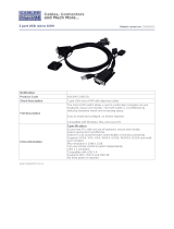
AOC-SIM1U/SIM1U+
Add-On Card
SIM1U
1

AOC-SIM1U/SIM1U+ User's Guide
1-2
AOC-SIM1U/SIM1U+ User's Guide
AOC-SIM1U/SIM1U+ User's Guide
AOC-SIM1U/SIM1U+ User's Guide
AOC-SIM1U/SIM1U+ User's Guide
AOC-SIM1U/SIM1U+ User's Guide
AOC-SIM1U/SIM1U+ User's Guide
AOC-SIM1U/SIM1U+ User's Guide
AOC-SIM1U/SIM1U+ User's Guide
AOC-SIM1U/SIM1U+ User's Guide
AOC-SIM1U/SIM1U+ User's Guide
AOC-SIM1U/SIM1U+ User's Guide
AOC-SIM1U/SIM1U+ User's Guide
AOC-SIM1U/SIM1U+ User's Guide
AOC-SIM1U/SIM1U+ User's Guide
Manual Revision 1.1a
Release Date: March 21, 2008
The information in this User’s Manual has been carefully reviewed and is believed to be accurate.
The vendor assumes no responsibility for any inaccuracies that may be contained in this document,
makes no commitment to update or to keep current the information in this manual, or to notify any
person or organization of the updates. Please Note: For the most up-to-date version of this
manual, please see our web site at www.supermicro.com.
Super Micro Computer, Inc. ("Supermicro") reserves the right to make changes to the product
described in this manual at any time and without notice. This product, including software, if any,
and documentation may not, in whole or in part, be copied, photocopied, reproduced, translated or
reduced to any medium or machine without prior written consent.
IN NO EVENT WILL SUPERMICRO BE LIABLE FOR DIRECT, INDIRECT, SPECIAL, INCIDENTAL,
SPECULATIVE OR CONSEQUENTIAL DAMAGES ARISING FROM THE USE OR INABILITY TO
USE THIS PRODUCT OR DOCUMENTATION, EVEN IF ADVISED OF THE POSSIBILITY OF
SUCH DAMAGES. IN PARTICULAR, SUPERMICRO SHALL NOT HAVE LIABILITY FOR ANY
HARDWARE, SOFTWARE, OR DATA STORED OR USED WITH THE PRODUCT, INCLUDING THE
COSTS OF REPAIRING, REPLACING, INTEGRATING, INSTALLING OR RECOVERING SUCH
HARDWARE, SOFTWARE, OR DATA.
Any disputes arising between manufacturer and customer shall be governed by the laws of Santa
Clara County in the State of California, USA. The State of California, County of Santa Clara shall
be the exclusive venue for the resolution of any such disputes. Super Micro's total liability for
all claims will not exceed the price paid for the hardware product.
FCC Statement: This equipment has been tested and found to comply with the limits for a Class
A digital device pursuant to Part 15 of the FCC Rules. These limits are designed to provide
reasonable protection against harmful interference when the equipment is operated in a commercial
environment. This equipment generates, uses, and can radiate radio frequency energy and, if not
installed and used in accordance with the manufacturer’s instruction manual, may cause harmful
interference with radio communications. Operation of this equipment in a residential area is likely
to cause harmful interference, in which case you will be required to correct the interference at your
own expense.
California Best Management Practices Regulations for Perchlorate Materials: This Perchlorate
warning applies only to products containing CR (Manganese Dioxide) Lithium coin cells. “Perchlorate
Material-special handling may apply. See www.dtsc.ca.gov/hazardouswaste/perchlorate”
WARNING: Handling of lead solder materials used in this
product may expose you to lead, a chemical known to
the State of California to cause birth defects and other
reproductive harm.
Unless you request and receive written permission from Super Micro Computer, Inc., you may not
copy any part of this document.
Information in this document is subject to change without notice. Other products and companies
referred to herein are trademarks or registered trademarks of their respective companies or mark
holders.
Copyright © 2008 by Super Micro Computer, Inc.
All rights reserved.
Printed in the United States of America

1-3
Chapter 1: Introduction
Table of Contents
Chapter I: Introduction .............................................................................1-4
1.1 Overview ..................................................................................................... 1-4
1.2 IPMI Version 2.0 ......................................................................................... 1-5
1.3 Product Features ........................................................................................ 1-5
1.4 Checklist .................................................................................................... 1-5
1.5 An Important Note to the User ................................................................... 1-5
1.6 Contacting Supermicro ............................................................................... 1-6
1.7 Returning Merchandise for Service .......................................................... 1-7
Chapter 2: Technical Specifications and Hardware Installation .......... 2-1
2.1 The Configuration of the AOC-SIM1U/SIM1U+ & the AOC-USB2RJ45 .... 2-1
2.2 AOC-SIM1U/SIM1U+ Connector and Jumper Locations .......................... 2-2
2.2.1 Front Components on the AOC-SIM1U(+) .............................................. 2-2
2.2.2 The Dedicated LAN LED on the AOC-USB2RJ45 .................................. 2-2
2.2.3 Front Connectors and LED Indicators ..................................................... 2-3
2.2.4 Dedicated LED Indicators ........................................................................ 2-4
2.2.5 Rear Components on the AOC-SIM1U(+) ............................................... 2-5
2.2.6 Rear LED Indicators ................................................................................ 2-5
2.3 Block Diagram ............................................................................................ 2-6
2.4 Installing the AOC-SIM1U(+) ...................................................................... 2-7
2.4.1 Safety Guidelines .................................................................................... 2-7
2.4.2 SIM1U Slot Locations .............................................................................. 2-8
Chapter 3: Software Application and Usage ..........................................3-1
3.1 Home Page ................................................................................................. 3-3
3.2 Functions Listed On the Home Page ......................................................... 3-5
3.2.1 Remote Control ....................................................................................... 3-5
3.2.2 Virtual Media ............................................................................................ 3-7
3.2.3 System Health ........................................................................................3-11
3.2.4 User Management ................................................................................. 3-17
3.2.5 KVM Settings ......................................................................................... 3-21
3.2.6 Device Settings ...................................................................................... 3-25
3.2.7 Maintenance .......................................................................................... 3-38
3.3 Remote Console Main Page .................................................................... 3-42
3.3.1 Remote Console Options ...................................................................... 3-43
Chapter 4: Frequently Asked Questions ................................................ 4-1

AOC-SIM1U/SIM1U+ User's Guide
1-4
AOC-SIM1U/SIM1U+ User's Guide
AOC-SIM1U/SIM1U+ User's Guide
AOC-SIM1U/SIM1U+ User's Guide
AOC-SIM1U/SIM1U+ User's Guide
AOC-SIM1U/SIM1U+ User's Guide
AOC-SIM1U/SIM1U+ User's Guide
AOC-SIM1U/SIM1U+ User's Guide
AOC-SIM1U/SIM1U+ User's Guide
AOC-SIM1U/SIM1U+ User's Guide
AOC-SIM1U/SIM1U+ User's Guide
AOC-SIM1U/SIM1U+ User's Guide
AOC-SIM1U/SIM1U+ User's Guide
AOC-SIM1U/SIM1U+ User's Guide
AOC-SIM1U/SIM1U+ User's Guide
Chapter 1
Introduction
This user's guide is written for system integrators, PC technicians and
knowledgeable PC users who intend to integrate Supermicro's unique IPMI 2.0
Management Utility with support of KVM-over-LAN () into their systems. It pro-
vides detailed information for the application and use of the AOC-SIM1U/SIM1U+
that supports remote access for system monitoring, diagnosis and management.
With the most advanced technologies built-in, the AOC-SIM1U/SIM1U+ offers a
complete, effi cient, and cost-effective remote server management.
(Note: KVM-over-LAN is only for the AOC-SIM1U+ only.)
1.1 Overview
The AOC-SIM1U/SIM1U+ is a highly effi cient, highly compatible and easy-to-use
IPMI card that allows the user to take advantage of the BMC, a baseboard man-
agement controller installed on a server motherboard and the IPMIView, an IPMI-
compliant management application software loaded in a PC, to provide serial links
between the main processor and other system components, allowing for network
interfacing via remote access. With an independent Raritan KIRA100 processor
built-in, the AOC-SIM1U/SIM1U+ provides the user with a solution to ease the com-
plex and expensive systems, allowing an administrator to access, monitor, diagnose
and manage network interfacing anywhere, anytime.
1.2 IPMI Version 2.0
The AOC-SIM1U/SIM1U+ supports the functionality of IPMI Version 2.0. The key
features include the following:
Supports IPMI 2.0 over LAN
Supports Serial over LAN
Supports Virtual Media over LAN
Supports KVM over LAN (For the AOC-SIM1U+ only)
Supports LAN Alerting-SNMP Trap
Supports Event Log
Offers OS (Operating System) Independency
Provides remote Hardware Health Monitoring via IPMI. Key features include
the following:
Temperature monitoring
Fan speed monitoring
Voltage monitoring
Power status monitoring, chassis intrusion monitoring
Remote power control to power-on, power-off or reboot a system
•
•
•
•
•
•
•
•
•
•
•
•
•

1-5
Chapter 1: Introduction
Remote access to text-based, graphic-based system information,
including BIOS configurations and OS operation information (KVM)
Remote management of utility/software applications
Provides Network Management Security via remote access/console redirec-
tion. Key features include:
User authentication enhancement
Encryption support enhancement, allowing for password configura-
tion security to protect sensitive data transferring via Serial over
LAN
Supports the following Management tools: IPMIView, CLI (Command Line
Interface) and Webengine
Supports RMCP & RMCP protocols
1.3. Product Features
(a) The AOC-SIM1U/SIM1U+ Series: (IPMI 2.0 with a Dedicated LAN)
• Slim size (4.6" W x 1.3" H) (116.84 mm W x 25.41 mm H)
• Supports IPMI over LAN
• Supports 1U and above
• Supports dedicated LAN
1.4 Checklist
If your shipping package came with missing or damaged parts, please contact
Supermicro's Tech. Support. Please refer to the following checklist when contacting
us.
i. AOC-SIM1U/SIM1U+
ii. Bracket: One bracket (SKT-0240L, including the AOC-USB2RJ45 Add-On Card,
the CBL-0165L Cable, Full and Low Profile I/O Brackets.) (The
SKT-0240L is
included in the SIM1U+ shipping package only.)
iii. CDR-SIMIPMI: One Installation CD
iv. White Box with Correct Barcode Label (showing AOC-SIM1U/SIM1U+).
1.5 An Important Note to the User
The graphics shown in this user's guide were based on the latest PCB Revision
available at the time of publishing of this guide. The SIM1U/SIM1U+ card you’ve
received may or may not look exactly the same as the graphics shown in this
user's guide.
•
•
•
•
•
•
•

AOC-SIM1U/SIM1U+ User's Guide
1-6
AOC-SIM1U/SIM1U+ User's Guide
AOC-SIM1U/SIM1U+ User's Guide
AOC-SIM1U/SIM1U+ User's Guide
AOC-SIM1U/SIM1U+ User's Guide
AOC-SIM1U/SIM1U+ User's Guide
AOC-SIM1U/SIM1U+ User's Guide
AOC-SIM1U/SIM1U+ User's Guide
AOC-SIM1U/SIM1U+ User's Guide
AOC-SIM1U/SIM1U+ User's Guide
AOC-SIM1U/SIM1U+ User's Guide
AOC-SIM1U/SIM1U+ User's Guide
AOC-SIM1U/SIM1U+ User's Guide
AOC-SIM1U/SIM1U+ User's Guide
AOC-SIM1U/SIM1U+ User's Guide
1.6 Contacting Supermicro
Headquarters
Address: Super Micro Computer, Inc.
980 Rock Ave.
San Jose, CA 95131 U.S.A.
Tel: +1 (408) 503-8000
Fax: +1 (408) 503-8008
Email: marketing@supermicro.com (General Information)
support@supermicro.com (Technical Support)
Web Site: www.supermicro.com
Europe
Address: Super Micro Computer B.V.
Het Sterrenbeeld 28, 5215 ML
's-Hertogenbosch, The Netherlands
Tel: +31 (0) 73-6400390
Fax: +31 (0) 73-6416525
Email: sales@supermicro.nl (General Information)
support@supermicro.nl (Technical Support)
rma@supermicro.nl (Customer Support)
Asia-Pacifi c
Address: Super Micro Computer, Inc.
4F, No. 232-1, Liancheng Rd.
Chung-Ho 235, Taipei County
Taiwan, R.O.C.
Tel: +886-(2) 8226-3990
Fax: +886-(2) 8226-3991
Web Site: www.supermicro.com.tw
Technical Support:
Email: support@supermicro.com.tw
Tel: 886-2-8226-1900

1-7
Chapter 1: Introduction
1.7 Returning Merchandise for Service
A receipt or copy of your invoice marked with the date of purchase is
required before any warranty service will be rendered. You can obtain
service by calling your vendor for a Returned Merchandise Authorization
(RMA) number. When returning to the manufacturer, the RMA number
should be prominently displayed on the outside of the shipping carton, and
mailed prepaid or hand-carried. Shipping and handling charges will be
applied for all orders that must be mailed when service is complete.
For faster service, RMA authorizations may be requested online (http://
www.supermicro.com/support/rma/).
Whenever possible, repack the add-on card in the original Supermicro box,
using the original packaging materials. If these are no longer available, be
sure to pack the add-on card in an anti-static bag and inside the box. Make
sure that there is enough packaging material surrounding the add-on card
so that it does not become damaged during shipping.
This warranty only covers normal consumer use and does not cover dam
-
ages incurred in shipping or from failure due to the alteration, misuse,
abuse or improper maintenance of products.
During the warranty period, contact your distributor first for any product
problems.

2-1
Chapter 2: Technical Specifi cations and Installation
Chapter 2
Technical Specifi cations and Hardware
Installation
2.1 Confi guring the AOC-SIM1U/SIM1U+ and
the AOC-USB2RJ45 Add-On Cards
The AOC-SIM1U/SIM1U+ Add-On Card is connected to a Dedicated LAN Ethernet
port located on the AOC-USB2RJ45 Add-On Card via an SMC Proprietary cable
(CBL-0165L) for External LAN access. One end of the CBL-0165L cable is con-
nected to the mini USB connector (J3) located on the AOC-SIM1U(+) card and the
other end to that of the AOC-USB2RJ45 card. There are two LEDs located on the
LAN port to indicate network links and activities. Refer to the picture below for the
confi guration.
*Note 1: You can also use LAN1 on the motherboard if you do not need the dedi-
cated LAN support. However, dedicated LAN is recommended for better graphic
support when the KVM feature is used.
*Note 2: The SKT-0240L is included in the SIM1U+ shipping package only.
AOC-SIM1U(+)
CBL-0165L Cable
AOC-USB2RJ45
Dedicated
Ethernet
(LAN) Port
Mini USB
Connector (J3)
Mini USB
Connector
Bracket
LAN LEDs
The SKT-0240L
(*Note 2 above)

AOC-SIM1U/SIM1U+ User's Guide
2-2
AOC-SIM1U/SIM1U+ User's Guide
AOC-SIM1U/SIM1U+ User's Guide
AOC-SIM1U/SIM1U+ User's Guide
AOC-SIM1U/SIM1U+ User's Guide
AOC-SIM1U/SIM1U+ User's Guide
AOC-SIM1U/SIM1U+ User's Guide
AOC-SIM1U/SIM1U+ User's Guide
SIM1U
1
2.2 AOC-SIM1U/SIM1U+ Connector and Jumper
Locations
5
6
2.2.1 Front Components on the AOC-SIM1U(+)
1. V-RAM (64Mb/166MHz)
2. SDRAM (128Mb/133MHz)
3. Transformer
4. J3: Mini USB 9-pin Connector (*Note)
5. JP5: Kira 100 Processor Reset (*Note)
6. D3: Standby Power LED Indicator
2.2.2 The Dedicated LAN LED Indicators on the AOC-USB2RJ45
8. Dedicated LAN LED Indicators
(*Note)
(*Note: See Pages 2-3, 2-4 for details)
48
Front View
1
2
3
V-RAM
SDRAM
SDRAM
Transformer
4
(*Note: " ", " ", or " " indicates Pin 1.)
2
J3
JP
5
D
3

2-3
Chapter 2: Technical Specifi cations and Installation
#4. J3: Mini USB Connector
There is a mini USB connector (J3) located on the
AOC-SIM1U/SIM1U+ and another mini USB con-
nector is located on the AOC-USB2RJ45. Use Cable
CBL-0165L to connect the two mini USB connectors
on both add-on cards for external LAN access. Refer
to Page 2-1 for details. See the table at right for the
pin defi nitions.
2.2.3 Front Connector and LED Indicators
Mini USB
Connector
AOC-USB2RJ45
Mini USB Pin Defi nitions
(J3)
Pin# Defi nition
1 Eth-TX_H
2 Eth-TX_L
3 Phy-100
4 Eth-RX_L
5 Eth-RX_H
6 Phy-ACT
7 Dedicated LAN-
Detected
8 3V-duall
9 Ground
AOC-SIM1U(+)
CBL-0165L Cable
(*Note)
#5. JP5: RISC CPU Reset
JP5 is used to reset the Kira 100 Processor, NIC,
and R.T. Close Pin 1 and Pin 2 to enable this
function.After a reset or AC power-on, the AOC-
SIM1U(+) will automatically detect if a cable (CBL-
0165L) is connected. If a cable is not detected,
the AOC-SIM1U(+) will transfer the "Remote
Control" Function to LAN1 on the motherboard.
If a cable is detected, the AOC-SIM1U(+) will use
the dedicated LAN attached to it via the mini USB
connector to manage motherboard activities via
Remote Console. See the table on the right for
jumper settings.
RISC CPU Reset
Setting Description
Open Disabled (*Default)
Close Enabled
Dedicated LAN
port
*Note: The SKT-0240L is included in the SIM1U+ shipping package only.
The SKT-0240L
(*Note below)

AOC-SIM1U/SIM1U+ User's Guide
2-4
AOC-SIM1U/SIM1U+ User's Guide
AOC-SIM1U/SIM1U+ User's Guide
AOC-SIM1U/SIM1U+ User's Guide
AOC-SIM1U/SIM1U+ User's Guide
AOC-SIM1U/SIM1U+ User's Guide
AOC-SIM1U/SIM1U+ User's Guide
AOC-SIM1U/SIM1U+ User's Guide
Link LED
Activity
LED
GLAN Link Indicator
LED Color Defi nition
Off
No Connection or 10 Mbps
Green 100 Mbps
GLAN Activity Indicator
Color Status Defi nition
Amber Flashing Active
#8. Dedicated LAN LED Indicators
There are two LAN LED Indicators located
on the (Dedicated) LAN port on the AOC-
USB2RJ45 Add-On Card. The green LED
indicates activity, while the power LED may
be green or off to indicate the speed of the
Ethernet connection. See the tables on the
right for more information.
#7. D3: Standby Power LED Indicator
When this LED is on, the standby power is
on. Be sure to remove power cables before
installing or removing components.
2.2.4 Dedicated LAN LED Indicators

2-5
Chapter 2: Technical Specifications and Installation
Rear View
Rear Side Components
1. Raritan's Kira 100 RISC System on Chip
2. Flash Memory
3. PHY LAN
4. Heartbeat LED
1
2
3
2.2.5 Rear Components on the AOC-SIM1U(+)
4
Kira 100 Processor
PHY LAN
Flash Memory
Heartbeat LED
#4 Heartbeat LED Indicator
Heartbeat LED, located on the rear side
of the AOC-SIM1U(+) card, indicates the
functionality and activity of the add-on
card. Heartbeat LED blinks when the
AOC-SIM1U(+) is active. However, when
the Linux OS and the drivers are being
loaded after each AC power-on or reset,
Heartbeat LED is off for about a minute.
Then, Heartbeat LED will be on again to
indicate that the AOC-SIM1U(+) is active.
See the table on the right for details.
Heartbeat LED
On (Blinking) SIM1U(+): active
Off (for 1 minute) Loading Firmware
Off (Continuously)
SIM1U is not active
2.2.6 Rear Side LED Indicators

AOC-SIM1U/SIM1U+ User's Guide
2-6
AOC-SIM1U/SIM1U+ User's Guide
AOC-SIM1U/SIM1U+ User's Guide
AOC-SIM1U/SIM1U+ User's Guide
AOC-SIM1U/SIM1U+ User's Guide
AOC-SIM1U/SIM1U+ User's Guide
AOC-SIM1U/SIM1U+ User's Guide
AOC-SIM1U/SIM1U+ User's Guide
2.3 Block Diagram
5
5
4
4
3
3
2
2
1
1
4
4
3
3
2
2
1
1
Title
Size Document Number Rev
Date: Sheet
of
UPER
S
®
2051 Junction Ave. San Jose CA, 95131
TEL : (408) 895-2000
CONFIDENTIAL - DO NOT DUPLICATE
1.02B
Block Diagram
2 9Wednesday, August 23, 2006
SIM1U
Title
Size Document Number Rev
Date: Sheet
of
UPER
S
®
2051 Junction Ave. San Jose CA, 95131
TEL : (408) 895-2000
CONFIDENTIAL - DO NOT DUPLICATE
1.02B
Block Diagram
2 9Wednesday, August 23, 2006
SIM1U
Title
Size Document Number Rev
Date: Sheet
of
UPER
S
®
2051 Junction Ave. San Jose CA, 95131
TEL : (408) 895-2000
CONFIDENTIAL - DO NOT DUPLICATE
1.02B
Block Diagram
2 9Wednesday, August 23, 2006
SIM1U
Ethernet PHY
DVO interface
UART Interface
USB Interface
LPC Interface
FML Interface
RMII
KIRA100
IPMI-200 Connector
Mother Board SMDATA
Mother Board SMCLK
Mother Board SMALT#
mini USB cable
RJ45
Dedicated LAN
miniUSB
CABLE detection (Lo active)
PIN 7
GPIO24
SIM1U only

2-7
Chapter 2: Technical Specifications and Installation
2.4 Installing the AOC-SIM1U/SIM1U+
To avoid personal injury and property damage, please carefully
follow all the safety steps listed below when installing the AOC-
SIM1U(+) into your system.
ESD Safety Guidelines
Electro-Static Discharge (ESD) can damage electronic components. To prevent dam-
age to your system, it is important to handle it very carefully. The following measures
are generally sufficient to protect your equipment from ESD.
• Use a grounded wrist strap designed to prevent static discharge.
• Touch a grounded metal object before removing a component from the antistatic
bag.
• Handle the add-on card by its edges only; do not touch its components, peripheral
chips, memory modules or gold contacts.
• When handling chips or modules, avoid touching their pins.
• Put the card and peripherals back into their antistatic bags when not in use.
General Safety Guidelines
• Always disconnect power cables before installing or removing any components
from the computer.
• Disconnect the power cable before removing any cable from the add-on card.
• Make sure that the SIM1U(+) add-on card is securely seated in the SIM1U slot to
prevent damage to the system due to power shortage. For SIM1U slot locations,
please refer to Section 2.4.2.
SMC Motherboards with SIM1U(+) support
The following Supermicro's motherboards support the AOC-SIM1U(+).
1. The X7DB8/X7DBE/X7DB8+/X7DBE+/X7DB8-X/X7DBE-X/X7DB3 Series
2. The X7DA8/X7DAE/X7DVA-8/X7DVA-E/X7DVL-3/i Series (*Note)
3. The X7DVL-E Series
4. The PDSM4+/PDSME+ Series
(*Note: KVM-over-LAN is not supported by the X7DA8/X7DAE/X7DVL-3/i.)
2.4.1 Safety Guidelines

AOC-SIM1U/SIM1U+ User's Guide
2-8
AOC-SIM1U/SIM1U+ User's Guide
AOC-SIM1U/SIM1U+ User's Guide
AOC-SIM1U/SIM1U+ User's Guide
AOC-SIM1U/SIM1U+ User's Guide
AOC-SIM1U/SIM1U+ User's Guide
AOC-SIM1U/SIM1U+ User's Guide
AOC-SIM1U/SIM1U+ User's Guide
2.4.2 SIM1U Slot Locations
To properly use the AOC-SIM1U(+), be sure to install it in the right slot. Refer to
the MB layouts below for SIM1U slot locations.
1. The X7DB8/X7DBE/X7DB8+/X7DBE+/X7DB8-X/X7DBE-X/X7DB3 Series and
2. The X7DA8/X7DAE/X7DVA-8/X7DVA-E/X7DVL-3/i Series (*Note)
SIM1U(+) Slot (Slot 7)
3. The X7DVL-E
SIM1U(+) Slot
4. The PDSM4+/PDSME+ Series
SIM1U(+) Slot
(*Note: KVM-over-LAN is not supported by
the X7DA8/X7DAE/X7DVL-3/i.)

Chapter 3: Software Application and Usage
3-1
Chapter 3
Software Application and Usage
With an independent I/O processor embedded in Raritan's Kira 100 RISC System
Chip, the AOC-SIM1U/SIM1U+ Add-On Card allows the user to access, monitor,
manage and interface with systems that are in remote locations via LAN. (See the
note on Page 3-2.) The necessary utilities for the access and configuration of the
add-on card are included on the Supermicro bootable CDs that came with your
card. This section provides information on the configuration and the access of the
IPMI card on the network.
Using the IPMICFG Utility to Configure IP/MAC Addresses and other
IPMI Network Settings
1. Run the ipmicfg utility from the bootable CD that came with your shipment.
2. Refer to the table below to configure the IP/MAC addresses.
Board IPMI MAC IP Communication through
X7 Series SIM1U IPMI Card Available
IP/DHCP
Dedicated LAN
LAN1 on MB
H8 DDR2
Memory
SIM1U IPMI Card Available
IP/DHCP
Dedicated LAN
LAN1 on MB
H8QM3/i-x SIM1U IPMI Card Available
IP/DHCP
Dedicated LAN
LAN1 LAN1 LAN1 on MB
3. Follow the instructions given in the Readme.txt file to configure Gateway IP/Net-
mask IP addresses, to enable/disable DHCP and to configure other IPMI settings.
Note 1: The Readme.txt file is included in the CD that came with your shipment. A
copy of the Readme.txt file, dated 07/05/2007, is also included below.
IPMICFG Version 1.04 Copyright 2007 SuperMicro Computer Inc.
Usage: IPMICFG Parameters (Example: IPMICFG -m 192.168.1.123)
-m Show IP and MAC
-m IP Set IP (format: ###.###.###.###)
-a MAC Set MAC (format: ##:##:##:##:##:##)
-k Show Subnet Mask
-k Mask Set Subnet Mask (format: ###.###.###.###)
-dhcp on Enable the DHCP
-dhcp off Disable the DHCP
-g Show Gateway IP
-g IP Set Gateway IP (format: ###.###.###.###)

3-2
AOC-SIM1U/SIM1U+ User's Guide
AOC-SIM1U/SIM1U+ User's Guide
AOC-SIM1U/SIM1U+ User's Guide
AOC-SIM1U/SIM1U+ User's Guide
AOC-SIM1U/SIM1U+ User's Guide
AOC-SIM1U/SIM1U+ User's Guide
AOC-SIM1U/SIM1U+ User's Guide
AOC-SIM1U/SIM1U+ User's Guide
AOC-SIM1U/SIM1U+ User's Guide
AOC-SIM1U/SIM1U+ User's Guide
AOC-SIM1U/SIM1U+ User's Guide
AOC-SIM1U/SIM1U+ User's Guide
AOC-SIM1U/SIM1U+ User's Guide
AOC-SIM1U/SIM1U+ User's Guide
AOC-SIM1U/SIM1U+ User's Guide
AOC-SIM1U/SIM1U+ User's Guide
To Access the SIM1U/SIM1U+ Card from a Computer Using the H8QM3-
2(+)/H8QMi-2(+) Motherboards
A. Using the Onboard LAN1 Connection
1. Choose a computer that is connected to the same network and open the
IPMIView utility.
2. Go to File>New>System. Type System Name, IP Address of LAN1, Description
in the appropriate blanks and press the <Enter> key.
3. Select the system from the IPMI Domain. Type the Login ID and Password in
the appropriate blanks to log into the IPMIView utility.
B. Using the Dedicated LAN
1. Choose a computer that is connected to the same network and open the
browser.
2. Type in the IP address of each server that you want to connect to in the ad-dress
bar in your browser.
3. Once the connection is made, the Log In screen as shown below will
display.
To Log In
Once you are connected to the remote server, the following Log In screen
displays.
1. Type in your Username in the "Username" box.
2. Type in your Password in the "Password" box and click on "Login."
(Note: The default username is ADMIN. The default password is ADMIN.)
3. The Home Page will display as follows:
Note: KVM-over-LAN is available on the AOC-SIM1U+ only. All features and options
related to the functionality of KVM-over-LAN are supported by the AOC-SIM1U+
only. In addition, KVM-over-LAN is not supported by the following motherboards:
1. X7DA8/X7DAE
2. X7DVL-3/X7DVL-i.

Chapter 3: Software Application and Usage
3-3
3.1 Home Page
3.1.1 Buttons from the Home Page
Home
Console
Logout
Remote Console Screen
1
2
3
4
5
6
7
8
9
Function Keys
Home: Click this icon to return to the Home Page.
Console: Click this icon to go to the Remote Console Screen.
Remote Console Screen: Displayed in the window is Remote Console
Screen. Click on this window to go to the Remote Console Screen.
Logout: Click on this icon to log out.
1
2
3
4
5
Refresh: Click on this icon to refresh the screen of the re-
mote console preview.
Power On: Click on this icon to power on the system of the
remote host.
6
7
Power Down: Click on this icon to power down the system
of the remote host.
Reset: Click on this icon to reset the remote host.
8

3-4
AOC-SIM1U/SIM1U+ User's Guide
AOC-SIM1U/SIM1U+ User's Guide
AOC-SIM1U/SIM1U+ User's Guide
AOC-SIM1U/SIM1U+ User's Guide
AOC-SIM1U/SIM1U+ User's Guide
AOC-SIM1U/SIM1U+ User's Guide
AOC-SIM1U/SIM1U+ User's Guide
AOC-SIM1U/SIM1U+ User's Guide
AOC-SIM1U/SIM1U+ User's Guide
AOC-SIM1U/SIM1U+ User's Guide
AOC-SIM1U/SIM1U+ User's Guide
AOC-SIM1U/SIM1U+ User's Guide
AOC-SIM1U/SIM1U+ User's Guide
AOC-SIM1U/SIM1U+ User's Guide
AOC-SIM1U/SIM1U+ User's Guide
AOC-SIM1U/SIM1U+ User's Guide
3.1.2 Function Keys from the Home Page
Click on these function keys to use the functions as specifi ed below.
(Note: Please see the next page for details on the functions specifi ed above.)
1
2
3
4
5
6
7
1. Remote Control: Click on this icon for remote access
and management of Video Console Redirection.
2. Virtual Media: Click on this icon to use virtual remote
media devices.
3. System Health: Click on this icon to view and manage
health monitoring for remote systems
4. User Management: Click on this icon for User Man-
agement.
5. KVM Settings: Click on this icon to confi gure key-
board, Video and mouse settings.
6. Device Settings: Click on this icon to confi gure device
settings.
7. Maintenance: Click on this icon to access, diagnose
and manage hardware devices
9

Chapter 3: Software Application and Usage
3-5
3.2 Functions Listed on the Home Page
3.2.1. Remote Control
Click on the icon of Remote Control to activate its submenus-KVM Console and
Remote Power as listed below.
a. KVM Console
Click on this item to configure keyboard, mouse or video settings for the remote
host.
1
Remote Console Screen
2
3
4
1
In the Single/Synchronized Mouse Mode, this cursor indicates the sys-
tem that is currently active. For the Double Mouse mode, this is the cur
-
sor for the remote host.
2
3
This icon indicates the availability of Keyboard and Mouse.
4
This icon indicates the number of networks (users) that are connected
via Console Redirection. (The number of figure icons indicates the num
-
ber of users connected.)
Explanation of Functions
This second mouse cursor only appears in the Double Mouse Mode.
This cursor represents the local mouse.
/