Page is loading ...

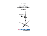
Model 2171B / 2170B
Antenna Positioning Tower
User Manual
Model 2171B boresight

ii www.ets-lindgren.com
ETS-Lindgren Inc. reserves the right to make changes to any products herein to improve
functioning or design. Although the information in this document has been carefully reviewed and
is believed to be reliable, ETS-Lindgren does not assume any liability arising out of the
application or use of any product or circuit described herein; nor does it convey any license under
its patent rights nor the rights of others. All trademarks are the property of their respective
owners.
© Copyright 2013–2018 by ETS-Lindgren Inc. All Rights Reserved. No part of this
document may be copied by any means without written permission from
ETS-Lindgren Inc.
Trademarks used in this document: The ETS-Lindgren logo is a registered trademark, and
EMCenter and EMControl are trademarks of ETS-Lindgren Inc.
Revision Record
MANUAL,2171B 2170B | Part #399364, Rev. E
Revision Description Date
A Initial Release December, 2013
B Updated Boom Load Limitations illustration March, 2014
C Updated Recommended Tools, Assembly
Instructions, Air Polarization Operation; added
Connecting Air Lines
January, 2015
D Updated bore sight link configurations; updated
drawings in back of manual
June, 2015
E Changed 2090 to EMCenter™ January, 2018

www.ets-lindgren.com iii
Table of Contents
Notes, Cautions, and Warnings ....................................................................... vii
1.0 Introduction ................................................................................................... 9
ETS-Lindgren Patented Boresight System ......................................................................... 9
Boresight Function (2171B Only) ............................................................................... 10
Non-Boresight Function ............................................................................................. 10
Positioning Controller (Required) ..................................................................................... 11
Standard Configuration ..................................................................................................... 12
Tower Assembly ......................................................................................................... 12
Variable Speed Motor ................................................................................................ 12
Links ........................................................................................................................... 12
Boresight with Centerline Pneumatic Polarization ..................................................... 12
Infrared (IR) Remote Controller ................................................................................. 12
Fiber Optic Control Cables ......................................................................................... 12
Fiber Optic Shield Room Penetration Kit ................................................................... 12
Optional Items................................................................................................................... 12
Offset Boom ............................................................................................................... 12
Additional Fiber Optic Cable ...................................................................................... 12
ETS-Lindgren Product Information Bulletin ...................................................................... 13
2.0 Maintenance ................................................................................................ 15
Air Cylinder Maintenance ................................................................................................. 15
Maintenance Schedule ..................................................................................................... 16
Every Three Months ................................................................................................... 16
Every Six Months ....................................................................................................... 16
Every Twelve Months ................................................................................................. 16
Replacement and Optional Parts...................................................................................... 16
Service Procedures .......................................................................................................... 17
Contacting ETS-Lindgren ........................................................................................... 17
Sending a Component for Service ............................................................................. 17
Calibration Services and Annual Calibration ............................................................. 17
3.0 Specifications .............................................................................................. 19
Electrical Specifications .................................................................................................... 19
Physical Specifications ..................................................................................................... 19
4.0 Electrical Installation .................................................................................. 21
Wire Gauge ....................................................................................................................... 21

iv www.ets-lindgren.com
Power Cord ....................................................................................................................... 21
Connecting the Positioning Controller .............................................................................. 22
EMCenter RF Modular Platform ................................................................................. 22
5.0 Assembly Instructions ............................................................................... 23
Included and Recommended Tools .................................................................................. 24
Included Tools ............................................................................................................ 24
Recommended Tools ................................................................................................. 24
Parts to Assemble ............................................................................................................ 24
Overview of Assembly Steps ............................................................................................ 25
Orientation of Parts during Assembly ............................................................................... 26
Mast Orientation ......................................................................................................... 26
Carrier Orientation ...................................................................................................... 26
Base Orientation ........................................................................................................ 27
Assembly Steps ................................................................................................................ 28
Step 1—Remove Carrier from Temporary Shipping Mast ......................................... 28
Step 2—Remove Temporary Shipping Mast from Base ............................................ 29
Step 3—Slide Carrier onto (Main) Mast ..................................................................... 30
Step 4—Begin Belt Installation .................................................................................. 31
Step 5—Insert Mast into Base ................................................................................... 34
Step 6—Connect Fiber Optic Cables ......................................................................... 35
Step 7—Adjust the Timing ......................................................................................... 37
Step 8—Finish Installing the Belt ............................................................................... 39
Step 9—Adjust Belt Tension ...................................................................................... 44
6.0 Additional Installation and Adjustments ................................................... 45
Install Cable Antenna ....................................................................................................... 45
Attach Optional Offset Boom ............................................................................................ 46
Install Boresight Links and Level Carrier (2171B Only) ................................................... 48
Install Boresight Links ................................................................................................ 49
Level Carrier ............................................................................................................... 50
Install Non-Boresight Links and Level Carrier (2171B Only) ............................................ 51
Install Non-Boresight Links ........................................................................................ 51
Level Carrier ............................................................................................................... 51
7.0 Operation ..................................................................................................... 53
Pre-Operational Checklist ................................................................................................. 53
Air Polarization Operation ................................................................................................. 54
Connecting Air Lines .................................................................................................. 55

www.ets-lindgren.com v
Infrared Remote Controller ............................................................................................... 56
EMCenter Modular RF Platform ....................................................................................... 56
Edit Configuration Parameters ................................................................................... 57
Tower Encoder Calibration ........................................................................................ 58
Start-Up ...................................................................................................................... 59
Shutdown ................................................................................................................... 59
Mounting Antennas ........................................................................................................... 59
Boom Load Limitations .............................................................................................. 60
Appendix A: Warranty ...................................................................................... 61
Appendix B: EC Declaration of Conformity .................................................... 63
Appendix C: Drawings ...................................................................................... 65

vi www.ets-lindgren.com
This page intentionally left blank.

www.ets-lindgren.com vii
Notes, Cautions, and Warnings
Note: Denotes helpful information intended to provide tips for better use of the
product.
CAUTION: Denotes a hazard. Failure to follow instructions could result in
minor personal injury and/or property damage. Included text gives proper
procedures.
WARNING: Denotes a hazard. Failure to follow instructions could result in
SEVERE personal injury and/or property damage. Included text gives
proper procedures.
Note: See the ETS-Lindgren Product Information Bulletin for safety, regulatory,
and other product marking information.

viii www.ets-lindgren.com
This page intentionally left blank.

www.ets-lindgren.com Introduction 9
1.0 Introduction
The ETS-Lindgren Model 2171B/2170B Antenna
Positioning Tower meets ANSI C63.4 requirements
for measurements above 1 GHz by keeping the
antenna aimed at the equipment under test (EUT) while
the antenna ascends and descends the mast. This is
especially useful when high gain directional antennas
are used.
The Model 2171B easily adjusts for non-boresight
testing and for 3-m, 5-m, and 10-m boresight testing.
The Model 2171B/2170B is constructed as a
single-piece mast of high density fiberglass-reinforced
polymer square tubing. This material has a high degree
of immunity from extended exposure to sunlight. The
Model 2171B/2170B is also designed with a reduced
base for easier maneuverability in smaller chambers.
A toothed belt drive provides smooth ascent and
descent of the carrier assembly. The belt is an
industrial grade composite that was selected for
strength and longevity.
Model 2171B boresight
(antenna not included)
The Model 2171B/2170B features variable speed operation with speed rates that
range from 3 cm/sec to 22 cm/sec, as controlled by an ETS-Lindgren positioning
controller. For more information on the positioning controller, see page 11.
The Model 2171B/2170B accepts stinger and other standard ETS-Lindgren antenna
mounts. See Mounting Antennas on page 59 for more information.
ETS-Lindgren Patented Boresight System
The Model 2171B provides the ETS-Lindgren patented boresight system to provide
direct antenna aim on EUT during scanning. This boresight meets the requirements
of ANSI C63.4 2003 and 2009 for compliance with FCC measurements above 1 GHz.
During scans, the boresight system maintains constant directional antenna
positioning while varying the angle between the antenna and the mast. This is
particularly important when using higher gain antennas of more than 3 dBi. As the
antenna is raised above the ground, the tilt of the antenna will maintain the EUT
within the half power (-3 dB) beamwidth.

10 Introduction www.ets-lindgren.com
Note: The following drawings use a generic positioning tower to illustrate
boresight and non-boresight function.
B
ORESIGHT
F
UNCTION
(2171B
O
NLY
)
N
ON
-B
ORESIGHT
F
UNCTION

www.ets-lindgren.com Introduction 11
Positioning Controller (Required)
A positioning controller such as the ETS-Lindgren EMCenter™ Modular RF Platform
(with EMControl™ Positioner Controller Plug-In Card) is required for operation, and is
sold separately. Contact ETS-Lindgren for ordering information. The EMCenter
replaces the 2090 Controller, which has been discontinued. The basic controller
configuration is an EMCenter with an EMControl card. This assembly is ETS part
number 125241.
Check ets-lindgren.com or contact ETS-Lindgren to ensure that your EMCenter, the
EMControl card, the backplane, and display all have the current firmware versions.
EMCenter: V5.21 (or later)
EMControl (7006-001) Card: V2.5.6 (or later)
Backplane: V2.3.0 (or later)
Display: V1.4.10 (or later)
The EMCenter is also expandable with a variety of additional options available.
Please contact ETS-Lindgren with any questions.
Note:
Existing ETS-Lindgren positioning controllers can be used with the
Model 2171B/2170B; contact ETS-Lindgren to confirm your controller is
installed with the required firmware.
The 2090 requires firmware revision V 3.21 or higher. It is available for
download at ets-lindgren.com and requires the program Flash Upgrade
Wizard V 4.0 (also available at ets-lindgren.com).

12 Introduction www.ets-lindgren.com
Standard Configuration
TOWER ASSEMBLY
Single-piece mast, castered base, carrier assembly
VARIABLE SPEED MOTOR
LINKS
Non-boresight and 3-, 5-, and 10-meter for boresight
BORESIGHT WITH CENTERLINE
PNEUMATIC POLARIZATION
With adjustable rotational velocity
INFRARED (IR) REMOTE
CONTROLLER
See page 53
FIBER OPTIC CONTROL
CABLES
3- and 10-meter
FIBER OPTIC SHIELD ROOM
PENETRATION KIT
Routes the fiber optic control cable from the
control room to the shield room while maintaining
shielding attenuation. The pieces are made of
brass for conductivity and provide attenuation of
greater than 100 dB at 10 GHz. A single 25-mm
(1.0-in) hole is required for mounting.
Optional Items
OFFSET BOOM
An optional offset boom is available (part# 118617). Contact ETS-Lindgren Sales
Department for more information.
ADDITIONAL FIBER OPTIC CABLE
Various lengths of fiber optic cable are available by custom order. The standard
length provided is 10 m (32.8 ft).

www.ets-lindgren.com Introduction 13
ETS-Lindgren Product Information Bulletin
See the ETS-Lindgren Product Information Bulletin included with your shipment for
the following:
Warranty information
Safety, regulatory, and other product marking information
Steps to receive your shipment
Steps to return a component for service
ETS Lindgren calibration service
ETS Lindgren contact information

14 Introduction www.ets-lindgren.com
This page intentionally left blank.

www.ets-lindgren.com Maintenance 15
2.0 Maintenance
CAUTION: Before performing any maintenance, follow the safety
information in the ETS-Lindgren Product Information Bulletin included
with your shipment.
WARNING: Maintenance of Model 2171B/2170B is limited to the
instructions provided here. If you have any questions concerning
maintenance, contact ETS-Lindgren Customer Service.
Do not make any modifications to this unit without consulting the factory
directly.
Only use replacement parts and fasteners ordered directly from the
factory.
This equipment should be operated and maintained by qualified personnel.
Disconnect all air supply lines when servicing pneumatic components.
Service equipment in accordance with the maintenance schedule provided.
Periodically check belt for wear.
Air Cylinder Maintenance
The air cylinder uses a special O-ring lubricant: silicon grease designed specifically
for O-rings. During maintenance apply this type of silicon grease to prevent excessive
wear of the O-rings.
WARRANTY

16 Maintenance www.ets-lindgren.com
Maintenance Schedule
E
VERY
T
HREE
M
ONTHS
Inspect belt for wear, tension, and cracking.
Check all screws and bolts to confirm that are tight per
assembly instructions.
Inspect bolts and hardware for breakage.
E
VERY
S
IX
M
ONTHS
Check connecting control and all cables for degradation from
environment and use. If necessary, replace per safety per
local electrical codes.
E
VERY
T
WELVE
M
ONTHS
Use high-grade silicone grease on all carrier rollers.
Replacement and Optional Parts
Note: ETS-Lindgren may substitute a similar part or new part number with the
same functionality for another part/part number. Contact ETS-Lindgren for
questions about part numbers and ordering parts.
Following are the part numbers for ordering replacement or optional parts for the
Model 2171B/2170B.
Part Description Part Number
Boresight links
3-meter link
5-meter links
10-meter links
119612
119613 (LH), 119665 (RH)
119614 (LH), 119666 (RH)
Non-boresight link
1 1/2-in link
1-in link
Cam knob
Cam lock knob
118050
118051
118052
118059
Offset boom, 2171B/2170B 118617
Timing Belt (33 ft required) 880393
Fuse, 5 x 20mm 3A Slow 480029

www.ets-lindgren.com Maintenance 17
Service Procedures
C
ONTACTING
ETS-L
INDGREN
Note: Please see ets-lindgren.com for a list of ETS-Lindgren offices, including
phone and email contact information.
S
ENDING A
C
OMPONENT FOR
S
ERVICE
For the steps to return a system or system component to ETS-Lindgren for service,
see the Product Information Bulletin included with your shipment.
C
ALIBRATION
S
ERVICES AND
A
NNUAL
C
ALIBRATION
See the Product Information Bulletin included with your shipment for information on
ETS-Lindgren calibration services.

18 Maintenance www.ets-lindgren.com
This page intentionally left blank.

www.ets-lindgren.com Specifications 19
3.0 Specifications
Electrical Specifications
Voltage:
220 VAC
Amp:
5.0
Line Frequency:
50/60 Hz
Phase:
Single
Physical Specifications
Polarization:
30
° per second
Scan Range:
1.0 m—4.0 m (39.37 in—157.48 in)
Speed Range:
3 cm/sec to 22 cm/sec
Cross-Boom Loading:
10.4 kg (23.0 lb)
Separation Distance
(boresight):
3 m, 5 m, 10 m
Weight (approximate):
80 kg (175.0 lb)
Maximum Overall Height:
2171B: 4.9 m (193 in)
2170B: 4.2 m (165 in)
Base Dimensions (LxW):
1.2 m (47.5 in) x 0.8 m (34.0 in)

20 Specifications www.ets-lindgren.com
This page intentionally left blank.
/