Mitsubishi Electric MELSEC iQ-R Simple Motion Module User manual
- Category
- Networking
- Type
- User manual

MELSEC iQ-R Simple Motion Module
User's Manual (Network)
-RD77GF4
-RD77GF8
-RD77GF16
-RD77GF32


1
SAFETY PRECAUTIONS
(Read these precautions before using this product.)
Before using this product, please read this manual and the relevant manuals carefully and pay full attention to safety to handle
the product correctly.
The precautions given in this manual are concerned with this product only. Refer to the MELSEC iQ-R Module Configuration
Manual for a description of the PLC system safety precautions.
In this manual, the safety precautions are classified into two levels: " WARNING" and " CAUTION".
Under some circumstances, failure to observe the precautions given under " CAUTION" may lead to serious
consequences.
Observe the precautions of both levels because they are important for personal and system safety.
Make sure that the end users read this manual and then keep the manual in a safe place for future reference.
[Design Precautions]
WARNING
● Configure safety circuits external to the programmable controller to ensure that the entire system
operates safely even when a fault occurs in the external power supply or the programmable controller.
Failure to do so may result in an accident due to an incorrect output or malfunction.
(1) Emergency stop circuits, protection circuits, and protective interlock circuits for conflicting
operations (such as forward/reverse rotations or upper/lower limit positioning) must be configured
external to the programmable controller.
(2) When the programmable controller detects an abnormal condition, it stops the operation and all
outputs are:
• Turned off if the overcurrent or overvoltage protection of the power supply module is activated.
• Held or turned off according to the parameter setting if the self-diagnostic function of the CPU
module detects an error such as a watchdog timer error.
(3) All outputs may be turned on if an error occurs in a part, such as an I/O control part, where the
CPU module cannot detect any error. To ensure safety operation in such a case, provide a safety
mechanism or a fail-safe circuit external to the programmable controller. For a fail-safe circuit
example, refer to "General Safety Requirements" in the MELSEC iQ-R Module Configuration
Manual.
(4) Outputs may remain on or off due to a failure of a component such as a relay and transistor in an
output circuit. Configure an external circuit for monitoring output signals that could cause a
serious accident.
● In an output circuit, when a load current exceeding the rated current or an overcurrent caused by a
load short-circuit flows for a long time, it may cause smoke and fire. To prevent this, configure an
external safety circuit, such as a fuse.
● Configure a circuit so that the programmable controller is turned on first and then the external power
supply. If the external power supply is turned on first, an accident may occur due to an incorrect output
or malfunction.
● For the operating status of each station after a communication failure, refer to manuals relevant to the
network. Incorrect output or malfunction due to a communication failure may result in an accident.
WARNING
Indicates that incorrect handling may cause hazardous conditions, resulting in
death or severe injury.
CAUTION
Indicates that incorrect handling may cause hazardous conditions, resulting in
minor or moderate injury or property damage.

2
[Design Precautions]
WARNING
● When connecting an external device with a CPU module or intelligent function module to modify data
of a running programmable controller, configure an interlock circuit in the program to ensure that the
entire system will always operate safely. For other forms of control (such as program modification,
parameter change, forced output, or operating status change) of a running programmable controller,
read the relevant manuals carefully and ensure that the operation is safe before proceeding. Improper
operation may damage machines or cause accidents.
● Especially, when a remote programmable controller is controlled by an external device, immediate
action cannot be taken if a problem occurs in the programmable controller due to a communication
failure. To prevent this, configure an interlock circuit in the program, and determine corrective actions
to be taken between the external device and CPU module in case of a communication failure.
● Do not write any data to the "system area" and "write-protect area" of the buffer memory in the
module. Also, do not use any "use prohibited" signals as an output signal from the CPU module to
each module. Doing so may cause malfunction of the programmable controller system. For the
"system area", "write-protect area", and the "use prohibited" signals, refer to the user's manual for the
module used.
● If a communication cable is disconnected, the network may be unstable, resulting in a communication
failure of multiple stations. Configure an interlock circuit in the program to ensure that the entire
system will always operate safely even if communications fail. Failure to do so may result in an
accident due to an incorrect output or malfunction.
● To maintain the safety of the programmable controller system against unauthorized access from
external devices via the network, take appropriate measures. To maintain the safety against
unauthorized access via the Internet, take measures such as installing a firewall.
● Configure safety circuits external to the programmable controller to ensure that the entire system
operates safely even when a fault occurs in the external power supply or the programmable controller.
Failure to do so may result in an accident due to an incorrect output or malfunction.
(1) Machine home position return is controlled by two kinds of data: a home position return direction
and a home position return speed. Deceleration starts when the proximity dog signal turns on. If
an incorrect home position return direction is set, motion control may continue without
deceleration. To prevent machine damage caused by this, configure an interlock circuit external to
the programmable controller.
(2) When the module detects an error, the motion slows down and stops or the motion rapidly stops,
depending on the stop group setting in parameter. Set the parameter to meet the specifications of
a positioning control system. In addition, set the home position return parameter and positioning
data within the specified setting range.
(3) Outputs may remain on or off, or become undefined due to a failure of a component such as an
insulation element and transistor in an output circuit, where the module cannot detect any error. In
a system that the incorrect output could cause a serious accident, configure an external circuit for
monitoring output signals.
● If safety standards (ex., robot safety rules, etc.,) apply to the system using the module, servo amplifier
and servomotor, make sure that the safety standards are satisfied.
● Construct a safety circuit externally of the module or servo amplifier if the abnormal operation of the
module or servo amplifier differs from the safety directive operation in the system.

3
[Design Precautions]
[Installation Precautions]
CAUTION
● Do not install the control lines or communication cables together with the main circuit lines or power
cables. Keep a distance of 100 mm or more between them. Failure to do so may result in malfunction
due to noise.
● During control of an inductive load such as a lamp, heater, or solenoid valve, a large current
(approximately ten times greater than normal) may flow when the output is turned from off to on.
Therefore, use a module that has a sufficient current rating.
● After the CPU module is powered on or is reset, the time taken to enter the RUN status varies
depending on the system configuration, parameter settings, and/or program size. Design circuits so
that the entire system will always operate safely, regardless of the time.
● Do not power off the programmable controller or reset the CPU module while the settings are being
written. Doing so will make the data in the flash ROM and SD memory card undefined. The values
need to be set in the buffer memory and written to the flash ROM and SD memory card again. Doing
so also may cause malfunction or failure of the module.
● When changing the operating status of the CPU module from external devices (such as the remote
RUN/STOP functions), select "Do Not Open by Program" for "Opening Method" of "Module
Parameter". If "Open by Program" is selected, an execution of the remote STOP function causes the
communication line to close. Consequently, the CPU module cannot reopen the line, and external
devices cannot execute the remote RUN function.
WARNING
● Shut off the external power supply (all phases) used in the system before mounting or removing the
module. Failure to do so may result in electric shock or cause the module to fail or malfunction.

4
[Installation Precautions]
[Wiring Precautions]
CAUTION
● Use the programmable controller in an environment that meets the general specifications in the Safety
Guidelines included with the base unit. Failure to do so may result in electric shock, fire, malfunction,
or damage to or deterioration of the product.
● To mount a module, place the concave part(s) located at the bottom onto the guide(s) of the base unit,
and push in the module until the hook(s) located at the top snaps into place. Incorrect interconnection
may cause malfunction, failure, or drop of the module.
● To mount a module with no module fixing hook, place the concave part(s) located at the bottom onto
the guide(s) of the base unit, push in the module, and fix it with screw(s). Incorrect interconnection
may cause malfunction, failure, or drop of the module.
● When using the programmable controller in an environment of frequent vibrations, fix the module with
a screw.
● Tighten the screws within the specified torque range. Undertightening can cause drop of the screw,
short circuit, or malfunction. Overtightening can damage the screw and/or module, resulting in drop,
short circuit, or malfunction.
● When using an extension cable, connect it to the extension cable connector of the base unit securely.
Check the connection for looseness. Poor contact may cause malfunction.
● When using an SD memory card, fully insert it into the SD memory card slot. Check that it is inserted
completely. Poor contact may cause malfunction.
● Securely insert an extended SRAM cassette into the cassette connector of the CPU module. After
insertion, close the cassette cover and check that the cassette is inserted completely. Poor contact
may cause malfunction.
● Do not directly touch any conductive parts and electronic components of the module, SD memory
card, extended SRAM cassette, or connector. Doing so can cause malfunction or failure of the
module.
WARNING
● Shut off the external power supply (all phases) used in the system before installation and wiring.
Failure to do so may result in electric shock or cause the module to fail or malfunction.
● After installation and wiring, attach a blank cover module (RG60) to each empty slot and an included
extension connector protective cover to the unused extension cable connector before powering on the
system for operation. Failure to do so may result in electric shock.

5
[Wiring Precautions]
CAUTION
● Individually ground the FG and LG terminals of the programmable controller with a ground resistance
of 100 ohms or less. Failure to do so may result in electric shock or malfunction.
● Use a solderless terminal with an insulation sleeve for terminal block wiring. Note that up to two
solderless terminals can be connected per terminal block.
● Use applicable solderless terminals and tighten them within the specified torque range. If any spade
solderless terminal is used, it may be disconnected when the terminal screw comes loose, resulting in
failure.
● Check the rated voltage and signal layout before wiring to the module, and connect the cables
correctly. Connecting a power supply with a different voltage rating or incorrect wiring may cause fire
or failure.
● Connectors for external devices must be crimped or pressed with the tool specified by the
manufacturer, or must be correctly soldered. Incomplete connections may cause short circuit, fire, or
malfunction.
● Securely connect the connector to the module. Poor contact may cause malfunction.
● Do not install the control lines or communication cables together with the main circuit lines or power
cables. Keep a distance of 100 mm or more between them. Failure to do so may result in malfunction
due to noise.
● When an overcurrent caused by an error of an external device or a failure of a module flows for a long
time, it may cause smoke and fire. To prevent this, configure an external safety circuit, such as a fuse.
● Place the cables in a duct or clamp them. If not, dangling cable may swing or inadvertently be pulled,
resulting in damage to the module or cables or malfunction due to poor contact. Do not clamp the
extension cables with the jacket stripped. Doing so may change the characteristics of the cables,
resulting in malfunction.
● When disconnecting the communication cable or power cable from the module, do not pull the cable
by the cable part. For the cable connected to the terminal block, loosen the terminal screws. Pulling
the cable connected to the module may result in malfunction or damage to the module or cable.
● Check the interface type and correctly connect the cable. Incorrect wiring (connecting the cable to an
incorrect interface) may cause failure of the module and external device.
● Tighten the terminal screws or connector screws within the specified torque range. Undertightening
can cause drop of the screw, short circuit, fire, or malfunction. Overtightening can damage the screw
and/or module, resulting in drop, short circuit, fire, or malfunction.
● Tighten the terminal block mounting screws, terminal screws, and module fixing screws within each
specified torque range. Undertightening of the terminal block mounting screws and terminal screws
can cause short circuit, fire, or malfunction. Overtightening of them can damage the screw and/or
module, resulting in drop, short circuit, or malfunction. Undertightening of the module fixing screws
can cause drop of the screw. Overtightening of them can damage the screw and/or module, resulting
in drop.
● When disconnecting the cable from the module, do not pull the cable by the cable part. For the cable
with connector, hold the connector part of the cable. For the cable connected to the terminal block,
loosen the terminal screw. Pulling the cable connected to the module may result in malfunction or
damage to the module or cable.

6
[Wiring Precautions]
[Startup and Maintenance Precautions]
CAUTION
● Prevent foreign matter such as dust or wire chips from entering the module. Such foreign matter can
cause a fire, failure, or malfunction.
● A protective film is attached to the top of the module to prevent foreign matter, such as wire chips,
from entering the module during wiring. Do not remove the film during wiring. Remove it for heat
dissipation before system operation.
● Programmable controllers must be installed in control panels. Connect the main power supply to the
power supply module in the control panel through a relay terminal block. Wiring and replacement of a
power supply module must be performed by qualified maintenance personnel with knowledge of
protection against electric shock. For wiring, refer to the MELSEC iQ-R Module Configuration Manual.
● For Ethernet cables to be used in the system, select the ones that meet the specifications in the user's
manual for the module used. If not, normal data transmission is not guaranteed.
WARNING
● Do not touch any terminal while power is on. Doing so will cause electric shock or malfunction.
● Correctly connect the battery connector. Do not charge, disassemble, heat, short-circuit, solder, or
throw the battery into the fire. Also, do not expose it to liquid or strong shock. Doing so will cause the
battery to produce heat, explode, ignite, or leak, resulting in injury and fire.
● Shut off the external power supply (all phases) used in the system before cleaning the module or
retightening the terminal screws, connector screws, or module fixing screws. Failure to do so may
result in electric shock.

7
[Startup and Maintenance Precautions]
CAUTION
● When connecting an external device with a CPU module or intelligent function module to modify data
of a running programmable controller, configure an interlock circuit in the program to ensure that the
entire system will always operate safely. For other forms of control (such as program modification,
parameter change, forced output, or operating status change) of a running programmable controller,
read the relevant manuals carefully and ensure that the operation is safe before proceeding. Improper
operation may damage machines or cause accidents.
● Especially, when a remote programmable controller is controlled by an external device, immediate
action cannot be taken if a problem occurs in the programmable controller due to a communication
failure. To prevent this, configure an interlock circuit in the program, and determine corrective actions
to be taken between the external device and CPU module in case of a communication failure.
● Do not disassemble or modify the modules. Doing so may cause failure, malfunction, injury, or a fire.
● Use any radio communication device such as a cellular phone or PHS (Personal Handy-phone
System) more than 25 cm away in all directions from the programmable controller. Failure to do so
may cause malfunction.
● Shut off the external power supply (all phases) used in the system before mounting or removing the
module. Failure to do so may cause the module to fail or malfunction.
● Tighten the screws within the specified torque range. Undertightening can cause drop of the
component or wire, short circuit, or malfunction. Overtightening can damage the screw and/or module,
resulting in drop, short circuit, or malfunction.
● After the first use of the product, do not mount/remove the module to/from the base unit, and the
terminal block to/from the module, and do not insert/remove the extended SRAM cassette to/from the
CPU module more than 50 times (IEC 61131-2 compliant) respectively. Exceeding the limit may cause
malfunction.
● After the first use of the product, do not insert/remove the SD memory card to/from the CPU module
more than 500 times. Exceeding the limit may cause malfunction.
● Do not touch the metal terminals on the back side of the SD memory card. Doing so may cause
malfunction or failure of the module.
● Do not touch the integrated circuits on the circuit board of an extended SRAM cassette. Doing so may
cause malfunction or failure of the module.
● Do not drop or apply shock to the battery to be installed in the module. Doing so may damage the
battery, causing the battery fluid to leak inside the battery. If the battery is dropped or any shock is
applied to it, dispose of it without using.
● Startup and maintenance of a control panel must be performed by qualified maintenance personnel
with knowledge of protection against electric shock. Lock the control panel so that only qualified
maintenance personnel can operate it.
● Before handling the module, touch a conducting object such as a grounded metal to discharge the
static electricity from the human body. Failure to do so may cause the module to fail or malfunction.
● Before testing the operation, set a low speed value for the speed limit parameter so that the operation
can be stopped immediately upon occurrence of a hazardous condition.
● Confirm and adjust the program and each parameter before operation. Unpredictable movements
may occur depending on the machine.
● When using the absolute position system function, on starting up, and when the module or absolute
position motor has been replaced, always perform a home position return.

8
[Startup and Maintenance Precautions]
[Operating Precautions]
[Disposal Precautions]
[Transportation Precautions]
CAUTION
● Before starting the operation, confirm the brake function.
● Do not perform a megger test (insulation resistance measurement) during inspection.
● After maintenance and inspections are completed, confirm that the position detection of the absolute
position detection function is correct.
● Lock the control panel and prevent access to those who are not certified to handle or install electric
equipment.
CAUTION
● When changing data and operating status, and modifying program of the running programmable
controller from an external device such as a personal computer connected to an intelligent function
module, read relevant manuals carefully and ensure the safety before operation. Incorrect change or
modification may cause system malfunction, damage to the machines, or accidents.
● Do not power off the programmable controller or reset the CPU module while the setting values in the
buffer memory are being written to the flash ROM in the module. Doing so will make the data in the
flash ROM and SD memory card undefined. The values need to be set in the buffer memory and
written to the flash ROM and SD memory card again. Doing so also may cause malfunction or failure
of the module.
● Note that when the reference axis speed is specified for interpolation operation, the speed of the
partner axis (2nd, 3rd, or 4th axis) may exceed the speed limit value.
● Do not go near the machine during test operations or during operations such as teaching. Doing so
may lead to injuries.
CAUTION
● When disposing of this product, treat it as industrial waste.
● When disposing of batteries, separate them from other wastes according to the local regulations. For
details on battery regulations in EU member states, refer to the MELSEC iQ-R Module Configuration
Manual.
CAUTION
● When transporting lithium batteries, follow the transportation regulations. For details on the regulated
models, refer to the MELSEC iQ-R Module Configuration Manual.
● The halogens (such as fluorine, chlorine, bromine, and iodine), which are contained in a fumigant
used for disinfection and pest control of wood packaging materials, may cause failure of the product.
Prevent the entry of fumigant residues into the product or consider other methods (such as heat
treatment) instead of fumigation. The disinfection and pest control measures must be applied to
unprocessed raw wood.

9
CONDITIONS OF USE FOR THE PRODUCT
(1) Mitsubishi programmable controller ("the PRODUCT") shall be used in conditions;
i) where any problem, fault or failure occurring in the PRODUCT, if any, shall not lead to any major or serious accident;
and
ii) where the backup and fail-safe function are systematically or automatically provided outside of the PRODUCT for the
case of any problem, fault or failure occurring in the PRODUCT.
(2) The PRODUCT has been designed and manufactured for the purpose of being used in general industries.
MITSUBISHI SHALL HAVE NO RESPONSIBILITY OR LIABILITY (INCLUDING, BUT NOT LIMITED TO ANY AND ALL
RESPONSIBILITY OR LIABILITY BASED ON CONTRACT, WARRANTY, TORT, PRODUCT LIABILITY) FOR ANY
INJURY OR DEATH TO PERSONS OR LOSS OR DAMAGE TO PROPERTY CAUSED BY the PRODUCT THAT ARE
OPERATED OR USED IN APPLICATION NOT INTENDED OR EXCLUDED BY INSTRUCTIONS, PRECAUTIONS, OR
WARNING CONTAINED IN MITSUBISHI'S USER, INSTRUCTION AND/OR SAFETY MANUALS, TECHNICAL
BULLETINS AND GUIDELINES FOR the PRODUCT.
("Prohibited Application")
Prohibited Applications include, but not limited to, the use of the PRODUCT in;
• Nuclear Power Plants and any other power plants operated by Power companies, and/or any other cases in which the
public could be affected if any problem or fault occurs in the PRODUCT.
• Railway companies or Public service purposes, and/or any other cases in which establishment of a special quality
assurance system is required by the Purchaser or End User.
• Aircraft or Aerospace, Medical applications, Train equipment, transport equipment such as Elevator and Escalator,
Incineration and Fuel devices, Vehicles, Manned transportation, Equipment for Recreation and Amusement, and
Safety devices, handling of Nuclear or Hazardous Materials or Chemicals, Mining and Drilling, and/or other
applications where there is a significant risk of injury to the public or property.
Notwithstanding the above, restrictions Mitsubishi may in its sole discretion, authorize use of the PRODUCT in one or
more of the Prohibited Applications, provided that the usage of the PRODUCT is limited only for the specific
applications agreed to by Mitsubishi and provided further that no special quality assurance or fail-safe, redundant or
other safety features which exceed the general specifications of the PRODUCTs are required. For details, please
contact the Mitsubishi representative in your region.

10
INTRODUCTION
Thank you for purchasing the Mitsubishi Electric MELSEC iQ-R series programmable controllers.
This manual describes the functions, programming, and troubleshooting of the relevant products listed below. Before using
this product, please read this manual and the relevant manuals carefully and develop familiarity with the functions and
performance of the MELSEC iQ-R series programmable controller to handle the product correctly.
When applying the program examples provided in this manual to an actual system, ensure the applicability and confirm that it
will not cause system control problems.
Please make sure that the end users read this manual.
Relevant products
RD77GF4, RD77GF8, RD77GF16, RD77GF32
COMPLIANCE WITH EMC AND LOW VOLTAGE
DIRECTIVES
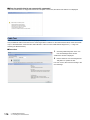
Method of ensuring compliance
To ensure that Mitsubishi programmable controllers maintain EMC and Low Voltage Directives when incorporated into other
machinery or equipment, certain measures may be necessary. Please refer to one of the following manuals.
MELSEC iQ-R Module Configuration Manual
Safety Guidelines (This manual is included with the base unit.)
The CE mark on the side of the programmable controller indicates compliance with EMC and Low Voltage Directives.
Additional measures
To ensure that this product maintains EMC and Low Voltage Directives, please refer to one of the following manuals.
MELSEC iQ-R Module Configuration Manual
Safety Guidelines (This manual is included with the base unit.)

11
CONTENTS
CONTENTS
SAFETY PRECAUTIONS . . . . . . . . . . . . . . . . . . . . . . . . . . . . . . . . . . . . . . . . . . . . . . . . . . . . . . . . . . . . . . . . . . . .1
CONDITIONS OF USE FOR THE PRODUCT . . . . . . . . . . . . . . . . . . . . . . . . . . . . . . . . . . . . . . . . . . . . . . . . . . . .9
INTRODUCTION. . . . . . . . . . . . . . . . . . . . . . . . . . . . . . . . . . . . . . . . . . . . . . . . . . . . . . . . . . . . . . . . . . . . . . . . . .10
COMPLIANCE WITH EMC AND LOW VOLTAGE DIRECTIVES . . . . . . . . . . . . . . . . . . . . . . . . . . . . . . . . . . . . .10
RELEVANT MANUALS . . . . . . . . . . . . . . . . . . . . . . . . . . . . . . . . . . . . . . . . . . . . . . . . . . . . . . . . . . . . . . . . . . . . .13
TERMS . . . . . . . . . . . . . . . . . . . . . . . . . . . . . . . . . . . . . . . . . . . . . . . . . . . . . . . . . . . . . . . . . . . . . . . . . . . . . . . . .14
CHAPTER 1 FUNCTIONS 17
1.1 Fixed Cycle Communication . . . . . . . . . . . . . . . . . . . . . . . . . . . . . . . . . . . . . . . . . . . . . . . . . . . . . . . . . . . . . . 17
1.2 CC-Link IE Field Network Synchronous Communication Function . . . . . . . . . . . . . . . . . . . . . . . . . . . . . . . 17
1.3 Cyclic Transmission . . . . . . . . . . . . . . . . . . . . . . . . . . . . . . . . . . . . . . . . . . . . . . . . . . . . . . . . . . . . . . . . . . . . . 18
Data flow and link device assignment . . . . . . . . . . . . . . . . . . . . . . . . . . . . . . . . . . . . . . . . . . . . . . . . . . . . . . . . . 18
Link refresh . . . . . . . . . . . . . . . . . . . . . . . . . . . . . . . . . . . . . . . . . . . . . . . . . . . . . . . . . . . . . . . . . . . . . . . . . . . . . 21
Direct access to link devices . . . . . . . . . . . . . . . . . . . . . . . . . . . . . . . . . . . . . . . . . . . . . . . . . . . . . . . . . . . . . . . . 23
Cyclic data integrity assurance . . . . . . . . . . . . . . . . . . . . . . . . . . . . . . . . . . . . . . . . . . . . . . . . . . . . . . . . . . . . . . 26
Interlink transmission. . . . . . . . . . . . . . . . . . . . . . . . . . . . . . . . . . . . . . . . . . . . . . . . . . . . . . . . . . . . . . . . . . . . . . 32
Input and output status settings when failure occurs. . . . . . . . . . . . . . . . . . . . . . . . . . . . . . . . . . . . . . . . . . . . . . 33
Output status setting for CPU STOP . . . . . . . . . . . . . . . . . . . . . . . . . . . . . . . . . . . . . . . . . . . . . . . . . . . . . . . . . . 34
Cyclic transmission stop and restart . . . . . . . . . . . . . . . . . . . . . . . . . . . . . . . . . . . . . . . . . . . . . . . . . . . . . . . . . . 35
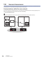
1.4 Transient Transmission . . . . . . . . . . . . . . . . . . . . . . . . . . . . . . . . . . . . . . . . . . . . . . . . . . . . . . . . . . . . . . . . . . 36
Communications within the same network . . . . . . . . . . . . . . . . . . . . . . . . . . . . . . . . . . . . . . . . . . . . . . . . . . . . .36
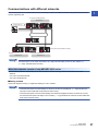
Communications with different networks . . . . . . . . . . . . . . . . . . . . . . . . . . . . . . . . . . . . . . . . . . . . . . . . . . . . . . . 37
1.5 IP Packet Transfer Function . . . . . . . . . . . . . . . . . . . . . . . . . . . . . . . . . . . . . . . . . . . . . . . . . . . . . . . . . . . . . . .40
System configuration. . . . . . . . . . . . . . . . . . . . . . . . . . . . . . . . . . . . . . . . . . . . . . . . . . . . . . . . . . . . . . . . . . . . . . 41
Setting . . . . . . . . . . . . . . . . . . . . . . . . . . . . . . . . . . . . . . . . . . . . . . . . . . . . . . . . . . . . . . . . . . . . . . . . . . . . . . . . . 42
IP communication test . . . . . . . . . . . . . . . . . . . . . . . . . . . . . . . . . . . . . . . . . . . . . . . . . . . . . . . . . . . . . . . . . . . . . 47
Access range. . . . . . . . . . . . . . . . . . . . . . . . . . . . . . . . . . . . . . . . . . . . . . . . . . . . . . . . . . . . . . . . . . . . . . . . . . . .49
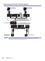
Relay using CC-Link IE Controller Network. . . . . . . . . . . . . . . . . . . . . . . . . . . . . . . . . . . . . . . . . . . . . . . . . . . . . 50
Precautions . . . . . . . . . . . . . . . . . . . . . . . . . . . . . . . . . . . . . . . . . . . . . . . . . . . . . . . . . . . . . . . . . . . . . . . . . . . . . 51
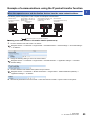
Example of communications using the IP packet transfer function . . . . . . . . . . . . . . . . . . . . . . . . . . . . . . . . . . . 53
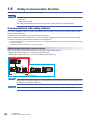
1.6 Safety Communication Function . . . . . . . . . . . . . . . . . . . . . . . . . . . . . . . . . . . . . . . . . . . . . . . . . . . . . . . . . . . 60
Communications with safety stations . . . . . . . . . . . . . . . . . . . . . . . . . . . . . . . . . . . . . . . . . . . . . . . . . . . . . . . . . 60
Safety station interlock function. . . . . . . . . . . . . . . . . . . . . . . . . . . . . . . . . . . . . . . . . . . . . . . . . . . . . . . . . . . . . . 63
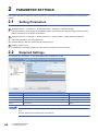
CHAPTER 2 PARAMETER SETTINGS 64
2.1 Setting Parameters . . . . . . . . . . . . . . . . . . . . . . . . . . . . . . . . . . . . . . . . . . . . . . . . . . . . . . . . . . . . . . . . . . . . . .64
2.2 Required Settings . . . . . . . . . . . . . . . . . . . . . . . . . . . . . . . . . . . . . . . . . . . . . . . . . . . . . . . . . . . . . . . . . . . . . . . 64
Station Type. . . . . . . . . . . . . . . . . . . . . . . . . . . . . . . . . . . . . . . . . . . . . . . . . . . . . . . . . . . . . . . . . . . . . . . . . . . . . 65
Network No.. . . . . . . . . . . . . . . . . . . . . . . . . . . . . . . . . . . . . . . . . . . . . . . . . . . . . . . . . . . . . . . . . . . . . . . . . . . . . 65
Station No.. . . . . . . . . . . . . . . . . . . . . . . . . . . . . . . . . . . . . . . . . . . . . . . . . . . . . . . . . . . . . . . . . . . . . . . . . . . . . . 65
Parameter Setting Method. . . . . . . . . . . . . . . . . . . . . . . . . . . . . . . . . . . . . . . . . . . . . . . . . . . . . . . . . . . . . . . . . . 65
2.3 Basic Settings . . . . . . . . . . . . . . . . . . . . . . . . . . . . . . . . . . . . . . . . . . . . . . . . . . . . . . . . . . . . . . . . . . . . . . . . . . 66
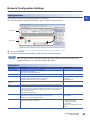
Network Configuration Settings. . . . . . . . . . . . . . . . . . . . . . . . . . . . . . . . . . . . . . . . . . . . . . . . . . . . . . . . . . . . . . 67
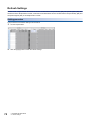
Refresh Settings . . . . . . . . . . . . . . . . . . . . . . . . . . . . . . . . . . . . . . . . . . . . . . . . . . . . . . . . . . . . . . . . . . . . . . . . . 70
Network Topology . . . . . . . . . . . . . . . . . . . . . . . . . . . . . . . . . . . . . . . . . . . . . . . . . . . . . . . . . . . . . . . . . . . . . . . .73
2.4 Application Settings . . . . . . . . . . . . . . . . . . . . . . . . . . . . . . . . . . . . . . . . . . . . . . . . . . . . . . . . . . . . . . . . . . . . .74
Supplementary Cyclic Settings . . . . . . . . . . . . . . . . . . . . . . . . . . . . . . . . . . . . . . . . . . . . . . . . . . . . . . . . . . . . . . 75
IP Address . . . . . . . . . . . . . . . . . . . . . . . . . . . . . . . . . . . . . . . . . . . . . . . . . . . . . . . . . . . . . . . . . . . . . . . . . . . . . . 75

12
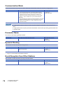
Communication Mode . . . . . . . . . . . . . . . . . . . . . . . . . . . . . . . . . . . . . . . . . . . . . . . . . . . . . . . . . . . . . . . . . . . . .76
Parameter Name . . . . . . . . . . . . . . . . . . . . . . . . . . . . . . . . . . . . . . . . . . . . . . . . . . . . . . . . . . . . . . . . . . . . . . . . . 76
Dynamic Routing . . . . . . . . . . . . . . . . . . . . . . . . . . . . . . . . . . . . . . . . . . . . . . . . . . . . . . . . . . . . . . . . . . . . . . . . . 76
Event Reception from Other Stations . . . . . . . . . . . . . . . . . . . . . . . . . . . . . . . . . . . . . . . . . . . . . . . . . . . . . . . . . 76
Module Operation Mode . . . . . . . . . . . . . . . . . . . . . . . . . . . . . . . . . . . . . . . . . . . . . . . . . . . . . . . . . . . . . . . . . . . 77
Interlink Transmission Settings . . . . . . . . . . . . . . . . . . . . . . . . . . . . . . . . . . . . . . . . . . . . . . . . . . . . . . . . . . . . . . 77
Safety Communication Setting . . . . . . . . . . . . . . . . . . . . . . . . . . . . . . . . . . . . . . . . . . . . . . . . . . . . . . . . . . . . . . 81
CHAPTER 3 PROGRAMMING 84
3.1 Precautions for Programming . . . . . . . . . . . . . . . . . . . . . . . . . . . . . . . . . . . . . . . . . . . . . . . . . . . . . . . . . . . . . 84
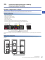
3.2 Communication Example of Safety Communication Function. . . . . . . . . . . . . . . . . . . . . . . . . . . . . . . . . . . 87
System configuration example . . . . . . . . . . . . . . . . . . . . . . . . . . . . . . . . . . . . . . . . . . . . . . . . . . . . . . . . . . . . . . 87
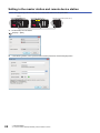
Setting in the master station and remote device station . . . . . . . . . . . . . . . . . . . . . . . . . . . . . . . . . . . . . . . . . . . 88
Setting in the local station . . . . . . . . . . . . . . . . . . . . . . . . . . . . . . . . . . . . . . . . . . . . . . . . . . . . . . . . . . . . . . . . . . 95
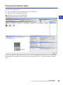
Checking the network status . . . . . . . . . . . . . . . . . . . . . . . . . . . . . . . . . . . . . . . . . . . . . . . . . . . . . . . . . . . . . . . . 97
Program examples . . . . . . . . . . . . . . . . . . . . . . . . . . . . . . . . . . . . . . . . . . . . . . . . . . . . . . . . . . . . . . . . . . . . . . . 98
CHAPTER 4 TROUBLESHOOTING 100
4.1 Checking with LED . . . . . . . . . . . . . . . . . . . . . . . . . . . . . . . . . . . . . . . . . . . . . . . . . . . . . . . . . . . . . . . . . . . . . 100
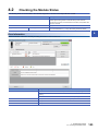
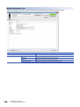
4.2 Checking the Module Status . . . . . . . . . . . . . . . . . . . . . . . . . . . . . . . . . . . . . . . . . . . . . . . . . . . . . . . . . . . . . 103
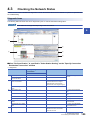
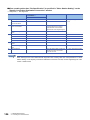
4.3 Checking the Network Status. . . . . . . . . . . . . . . . . . . . . . . . . . . . . . . . . . . . . . . . . . . . . . . . . . . . . . . . . . . . . 105
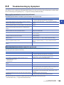
4.4 Troubleshooting by Symptom . . . . . . . . . . . . . . . . . . . . . . . . . . . . . . . . . . . . . . . . . . . . . . . . . . . . . . . . . . . . 125
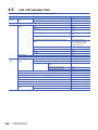
4.5 List of Parameter Nos. . . . . . . . . . . . . . . . . . . . . . . . . . . . . . . . . . . . . . . . . . . . . . . . . . . . . . . . . . . . . . . . . . . 130
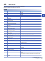
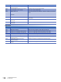
4.6 Event List . . . . . . . . . . . . . . . . . . . . . . . . . . . . . . . . . . . . . . . . . . . . . . . . . . . . . . . . . . . . . . . . . . . . . . . . . . . . . 131
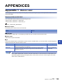
APPENDICES 133
Appendix 1 Module Label . . . . . . . . . . . . . . . . . . . . . . . . . . . . . . . . . . . . . . . . . . . . . . . . . . . . . . . . . . . . . . . . . . . . . 133
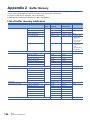
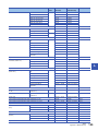
Appendix 2 Buffer Memory . . . . . . . . . . . . . . . . . . . . . . . . . . . . . . . . . . . . . . . . . . . . . . . . . . . . . . . . . . . . . . . . . . . . 134
List of buffer memory addresses . . . . . . . . . . . . . . . . . . . . . . . . . . . . . . . . . . . . . . . . . . . . . . . . . . . . . . . . . . . . 134
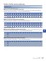
Details of buffer memory addresses . . . . . . . . . . . . . . . . . . . . . . . . . . . . . . . . . . . . . . . . . . . . . . . . . . . . . . . . . 137
Appendix 3 List of Link Special Relay (SB) . . . . . . . . . . . . . . . . . . . . . . . . . . . . . . . . . . . . . . . . . . . . . . . . . . . . . . . 143
Appendix 4 List of Link Special Register (SW) . . . . . . . . . . . . . . . . . . . . . . . . . . . . . . . . . . . . . . . . . . . . . . . . . . . . 152
Appendix 5 Dedicated Instruction . . . . . . . . . . . . . . . . . . . . . . . . . . . . . . . . . . . . . . . . . . . . . . . . . . . . . . . . . . . . . . 166
Precautions for dedicated instructions. . . . . . . . . . . . . . . . . . . . . . . . . . . . . . . . . . . . . . . . . . . . . . . . . . . . . . . . 167
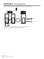
Appendix 6 Processing Time . . . . . . . . . . . . . . . . . . . . . . . . . . . . . . . . . . . . . . . . . . . . . . . . . . . . . . . . . . . . . . . . . . 168
Link scan time . . . . . . . . . . . . . . . . . . . . . . . . . . . . . . . . . . . . . . . . . . . . . . . . . . . . . . . . . . . . . . . . . . . . . . . . . . 169
Cyclic transmission delay time . . . . . . . . . . . . . . . . . . . . . . . . . . . . . . . . . . . . . . . . . . . . . . . . . . . . . . . . . . . . . 170
Interlink transmission time . . . . . . . . . . . . . . . . . . . . . . . . . . . . . . . . . . . . . . . . . . . . . . . . . . . . . . . . . . . . . . . . . 173
Transmission delay time of safety communications . . . . . . . . . . . . . . . . . . . . . . . . . . . . . . . . . . . . . . . . . . . . . 174
Appendix 7 Differences in Cyclic Transmission Modes . . . . . . . . . . . . . . . . . . . . . . . . . . . . . . . . . . . . . . . . . . . . . 177
INDEX 178
REVISIONS. . . . . . . . . . . . . . . . . . . . . . . . . . . . . . . . . . . . . . . . . . . . . . . . . . . . . . . . . . . . . . . . . . . . . . . . . . . . .180
WARRANTY . . . . . . . . . . . . . . . . . . . . . . . . . . . . . . . . . . . . . . . . . . . . . . . . . . . . . . . . . . . . . . . . . . . . . . . . . . . .181
TRADEMARKS . . . . . . . . . . . . . . . . . . . . . . . . . . . . . . . . . . . . . . . . . . . . . . . . . . . . . . . . . . . . . . . . . . . . . . . . . .182

13
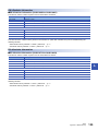
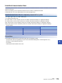
RELEVANT MANUALS
This manual does not include information on the module function blocks.
For details, refer to the Function Block Reference for the module used.
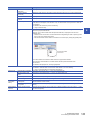
e-Manual refers to the Mitsubishi Electric FA electronic book manuals that can be browsed using a dedicated
tool.
e-Manual has the following features:
• Required information can be cross-searched in multiple manuals.
• Other manuals can be accessed from the links in the manual.
• The hardware specifications of each part can be found from the product figures.
• Pages that users often browse can be bookmarked.
• Sample programs can be copied to an engineering tool.
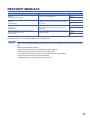
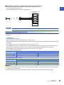
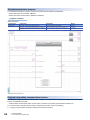
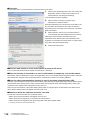
Manual name [manual number] Description Available form
MELSEC iQ-R Simple Motion Module User's Manual
(Network)
[IB-0300307ENG] (This manual)
Functions, parameter settings, troubleshooting, and buffer
memory of CC-Link IE Field Network
Print book
e-Manual
PDF
MELSEC iQ-R Simple Motion Module User's Manual
(Startup)
[IB-0300245ENG]
Specifications, procedures before operation, system
configuration, wiring, and operation examples of the Simple
Motion module
Print book
e-Manual
PDF
MELSEC iQ-R Simple Motion Module User's Manual
(Application)
[IB-0300247ENG]
Functions, input/output signals, buffer memory, parameter
settings, programming, and troubleshooting of the Simple
Motion module
Print book
e-Manual
PDF
MELSEC iQ-R Simple Motion Module User's Manual
(Advanced Synchronous Control)
[IB-0300249ENG]
Functions and programming for the synchronous control of the
Simple Motion module
Print book
e-Manual
PDF

14
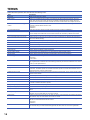
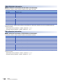
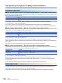
TERMS
Unless otherwise specified, this manual uses the following terms.
Term Description
Baton pass A token to send data over a network
Buffer memory A memory in an intelligent function module, where data (such as setting values and monitoring values) are
stored. When using the CPU module, the memory is indicated for storing data (such as setting values and
monitored values) of the Ethernet function and data used for data communication of the multiple CPU function.
CC-Link IE Controller Network-equipped
module
A generic term for the RJ71GP21-SX CC-Link IE Controller Network module and the following modules when the
CC-Link IE Controller Network function is used:
• RJ71EN71
• RnENCPU
CC-Link IE Field Network A high-speed and large-capacity open field network that is based on Ethernet (1000BASE-T)
Control CPU A CPU module that controls connected I/O modules and intelligent function modules. In a multiple CPU system,
there are multiple CPU modules and each connected module can be controlled by a different CPU module.
CPU module The abbreviation for the MELSEC iQ-R series CPU module
CPU module (built-in Ethernet port part) A built-in Ethernet port part of the CPU module (CPU part for the RnENCPU) (MELSEC iQ-R Ethernet/CC-
Link IE User's Manual (Startup))
Cyclic transmission A function by which data are periodically exchanged among stations on the network using link devices
Data link A generic term for cyclic transmission and transient transmission
Dedicated instruction An instruction for using functions of the module
Device A device (X, Y, M, D, or others) in a CPU module
Disconnection A process of stopping data link if a data link error occurs
Engineering tool A generic term for GX Works3 and MR Configurator2
Ethernet adapter module The abbreviation for the NZ2GF-ETB CC-Link IE Field Network Ethernet adapter module
Ethernet device A generic term for the devices supporting IP communication (such as personal computers)
Ethernet-equipped module A generic term for the following modules when the Ethernet function is used
• RJ71EN71
• CPU module
Global label A label that is enabled for all program data when creating multiple program data in the project. There are two
types of global labels: module label that is automatically generated by GX Works3 and label that can be created
for the any of the specified devices.
Head module The abbreviation for the LJ72GF15-T2 CC-Link IE Field Network head module
Intelligent device station A station that exchanges I/O signals (bit data) and I/O data (word data) with another station by cyclic
transmission. This station responds to a transient transmission request from another station and also issues a
transient transmission request to another station.
Intelligent function module A MELSEC iQ-R series module that has functions other than input and output, such as an A/D converter module
and D/A converter module
Label A label that represents a device in a given character string
Link device A device (RX, RY, RWr, or RWw) in a module on CC-Link IE Field Network
Link refresh Automatic data transfer between a link device of the Simple Motion module and a device in a CPU module
Link scan (link scan time) Time required for all the stations on the network to transmit data. The link scan time depends on data volume and
the number of transient transmission requests.
Link special register (SW) Word data that indicates the operating status and data link status of a module on CC-Link IE Field Network
Link special relay (SB) Bit data that indicates the operating status and data link status of a module on CC-Link IE Field Network
Local station A station that performs cyclic transmission and transient transmission with the master station and other local
stations
Master operating station A station that controls the entire network in the network where a master station and submaster station are
connected. Only one master station can be used in a network.
Master station A station that controls the entire network. This station can perform cyclic transmission and transient transmission
with all stations. Only one master station can be used in a network.
Master/local module A generic term for the RJ71GF11-T2 CC-Link IE Field Network master/local module and the following modules
when the CC-Link IE Field Network function is used:
• RJ71EN71
• RnENCPU
Module label A label that represents one of memory areas (I/O signals and buffer memory areas) specific to each module in a
given character string. GX Works3 automatically generates this label, which can be used as a global label.

15
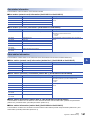
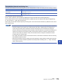
Network module A generic term for the following modules:
• Ethernet interface module
• CC-Link IE Controller Network module
• Module on CC-Link IE Field Network
• MELSECNET/H network module
• MELSECNET/10 network module
• RnENCPU (network part)
RAS The abbreviation for Reliability, Availability, and Serviceability. This term refers to usability of automated
equipment.
READ A generic term for the JP.READ and GP.READ
RECV A generic term for the JP.RECV and GP.RECV
RECVS A generic term for the G.RECVS and Z.RECVS
Relay station A station that includes two or more network modules. Data are passed through this station to stations on other
networks
REMFR A generic term for the JP.REMFR and ZP.REMFR
Remote device station A station that exchanges I/O signals (bit data) and I/O data (word data) with another station by cyclic
transmission. This station responds to a transient transmission request from another station.
Remote head module The abbreviation for the RJ72GF15-T2 CC-Link IE Field Network remote head module
Remote I/O station A station that exchanges I/O signals (bit data) with the master station by cyclic transmission
Remote input (RX) Bit data input from a slave station to the master station (For some areas in a local station, data are input in the
opposite direction.)
Remote output (RY) Bit data output from the master station to a slave station (For some areas in a local station, data are output in the
opposite direction.)
Remote register (RWr) Word data input from a slave station to the master station (For some areas in a local station, data are input in the
opposite direction.)
Remote register (RWw) Word data output from the master station to a slave station (For some areas in a local station, data are output in
the opposite direction.)
REMTO A generic term for the JP.REMTO and ZP.REMTO
REQ A generic term for the J.REQ, JP.REQ, G.REQ, and GP.REQ
Reserved station A station reserved for future use. This station is not actually connected, but counted as a connected station.
Return A process of restarting data link when a station recovers from an error
RIRD A generic term for the J.RIRD, JP.RIRD, G.RIRD, and GP.RIRD
RIWT A generic term for the J.RIWT, JP.RIWT, G.RIWT, and GP.RIWT
RnENCPU A generic term for the R04ENCPU, R08ENCPU, R16ENCPU, R32ENCPU, and R120ENCPU
RnENCPU (CPU part) The left side (CPU part) of the RnENCPU (MELSEC iQ-R Ethernet/CC-Link IE User's Manual (Startup))
RnENCPU (network part) The right side (network part) of the RnENCPU (MELSEC iQ-R Ethernet/CC-Link IE User's Manual (Startup))
Routing A process of selecting paths for communication with other networks. There are two types of routing: dynamic
routing that auto-selects the communication routes, and static routing where communication routes are arbitrarily
set.
Safety communications A function to exchange safety data between safety stations on the same network
Safety connection A connection established for safety communications
Safety CPU A generic term for the R08SFCPU, R16SFCPU, R32SFCPU, and R120SFCPU
Safety data Data exchanged through safety communications
Safety device A device that can be used in safety programs
Safety function module Another term for the R6SFM
Safety station A generic term for a station that performs safety communications and standard communications
Seamless communication Communication that allows users to access a different kind of networks without having to consider the
differences as if data were exchanged within one single network
SEND A generic term for the JP.SEND and GP.SEND
Servo amplifier A generic term for a drive unit
Unless specified in particular, indicates the motor driver unit of the sequential command method which is
controlled by the Simple Motion module (belonging to own station).
Simple Motion module The abbreviation for the MELSEC iQ-R series Simple Motion module (compatible with CC-Link IE Field Network)
• RD77GF
Slave station A generic term for a local station, remote I/O station, remote device station, and intelligent device station
SREAD A generic term for the JP.SREAD and GP.SREAD
Submaster operating station A station that monitors the status of a master operating station in the network where a master station and
submaster station are connected. Only one master station can be used in a network.
Term Description

16
Submaster station A station that serves as a master station to control the entire network if the master station is disconnected. Only
one master station can be used in a network.
SWRITE A generic term for the JP.SWRITE and GP.SWRITE
System switching A function which switches the systems between the control system and the standby system to continue operation
of the redundant system when a failure or an error occurs in the control system
Transient transmission A function of communication with another station, which is used when requested by a dedicated instruction or the
engineering tool
WRITE A generic term for the JP.WRITE and GP.WRITE
Term Description

1 FUNCTIONS
1.1 Fixed Cycle Communication
17
1
1 FUNCTIONS
1.1 Fixed Cycle Communication
The communication cycle of the Simple Motion module is fixed cycle. The communication is performed with slave modules in
a cycle set in the inter-module synchronization cycle setting.
Refer to the following for details.
MELSEC iQ-R Inter-Module Synchronization Function Reference Manual
1.2 CC-Link IE Field Network Synchronous
Communication Function
A slave module which supports the CC-Link IE Field Network synchronous communication function operates synchronously
with the inter-module synchronization cycle of the Simple Motion module (the communication cycle of CC-Link IE Field
Network). Therefore, the operation timing between the Simple Motion module and each slave module can be synchronized.
A slave module which does not support the CC-Link IE Field Network synchronous communication function is also
connectable. However, the operation is not synchronized with the inter-module synchronization cycle of the Simple Motion
module. Therefore, the operation timing of the slave module is not synchronized with the Simple Motion module.
Refer to the following for details.
MELSEC iQ-R Inter-Module Synchronization Function Reference Manual

18
1 FUNCTIONS
1.3 Cyclic Transmission
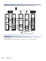
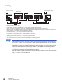
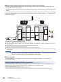
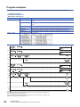
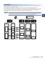
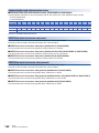
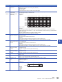
1.3 Cyclic Transmission
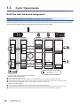
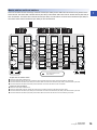
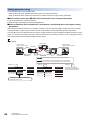
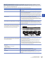
This function allows data to be periodically exchanged among stations on the same network using link devices.
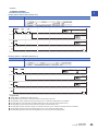
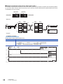
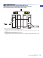
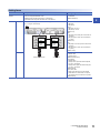
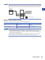
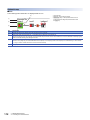
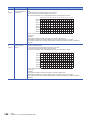
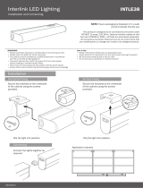
Data flow and link device assignment
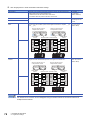
Master station and slave stations (except for local stations)
One-to-one communication is possible between the master and slave stations. The status data of the link devices (RY, RWw)
of the master station is output to the external device of the slave station, and the input status information from the external
device of the slave station is stored in the link devices (RX, RWr) of the master station.
*1 There is no RX or RY depending on the slave module.
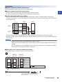
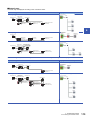
• Output from the master station
• Input from the slave station
The device of the CPU module turns on.
The status data of the device of the CPU module are stored in the link devices (RY, RWw) of the master station by link refresh.
The status data of the link devices (RY, RWw) of the master station are stored in the link devices (RY, RWw) of each slave station by link scan.
The status data of the link devices (RY, RWw) of the slave station are output to the external device.
The status data of the external device are stored in the link devices (RX, RWr) of the slave station.
The status data of the link devices (RX, RWr) of the slave station are stored in the link devices (RX, RWr) of the master station by link scan.
The status data of the link devices (RX, RWr) of the master station are stored in the devices of the CPU module by link refresh.
RX, RWr
*1
RX, RWr
*1
RX, RWr
END
RY, RWw
*1
RY, RWw
*1
RY, RWw
END
RX, RWr
M0
Y
Ò
Ó
Ø
×
×
×
Ô
Ô
Ô
Ö
Õ
Slave station
Station No.1
Slave station
Station No.2
Slave station
Station No.3
Station
No.1
Station
No.2
Station
No.3
External device
External device
CPU module
Device
Device
Station No.1
Station No.2
Station No.3
Station No.0
Area where data is sent to
other stations
Station
No.1
Station
No.2
Station
No.3
Station No.1
Station No.2
Station No.3
Link
refresh
Link
refresh
Link
scan
Inter-module
synchronization
cycle
Inter-module
synchronization
cycle
Master station
(Simple
Motion
module)
RY, RWw
Page is loading ...
Page is loading ...
Page is loading ...
Page is loading ...
Page is loading ...
Page is loading ...
Page is loading ...
Page is loading ...
Page is loading ...
Page is loading ...
Page is loading ...
Page is loading ...
Page is loading ...
Page is loading ...
Page is loading ...
Page is loading ...
Page is loading ...
Page is loading ...
Page is loading ...
Page is loading ...
Page is loading ...
Page is loading ...
Page is loading ...
Page is loading ...
Page is loading ...
Page is loading ...
Page is loading ...
Page is loading ...
Page is loading ...
Page is loading ...
Page is loading ...
Page is loading ...
Page is loading ...
Page is loading ...
Page is loading ...
Page is loading ...
Page is loading ...
Page is loading ...
Page is loading ...
Page is loading ...
Page is loading ...
Page is loading ...
Page is loading ...
Page is loading ...
Page is loading ...
Page is loading ...
Page is loading ...
Page is loading ...
Page is loading ...
Page is loading ...
Page is loading ...
Page is loading ...
Page is loading ...
Page is loading ...
Page is loading ...
Page is loading ...
Page is loading ...
Page is loading ...
Page is loading ...
Page is loading ...
Page is loading ...
Page is loading ...
Page is loading ...
Page is loading ...
Page is loading ...
Page is loading ...
Page is loading ...
Page is loading ...
Page is loading ...
Page is loading ...
Page is loading ...
Page is loading ...
Page is loading ...
Page is loading ...
Page is loading ...
Page is loading ...
Page is loading ...
Page is loading ...
Page is loading ...
Page is loading ...
Page is loading ...
Page is loading ...
Page is loading ...
Page is loading ...
Page is loading ...
Page is loading ...
Page is loading ...
Page is loading ...
Page is loading ...
Page is loading ...
Page is loading ...
Page is loading ...
Page is loading ...
Page is loading ...
Page is loading ...
Page is loading ...
Page is loading ...
Page is loading ...
Page is loading ...
Page is loading ...
Page is loading ...
Page is loading ...
Page is loading ...
Page is loading ...
Page is loading ...
Page is loading ...
Page is loading ...
Page is loading ...
Page is loading ...
Page is loading ...
Page is loading ...
Page is loading ...
Page is loading ...
Page is loading ...
Page is loading ...
Page is loading ...
Page is loading ...
Page is loading ...
Page is loading ...
Page is loading ...
Page is loading ...
Page is loading ...
Page is loading ...
Page is loading ...
Page is loading ...
Page is loading ...
Page is loading ...
Page is loading ...
Page is loading ...
Page is loading ...
Page is loading ...
Page is loading ...
Page is loading ...
Page is loading ...
Page is loading ...
Page is loading ...
Page is loading ...
Page is loading ...
Page is loading ...
Page is loading ...
Page is loading ...
Page is loading ...
Page is loading ...
Page is loading ...
Page is loading ...
Page is loading ...
Page is loading ...
Page is loading ...
Page is loading ...
Page is loading ...
Page is loading ...
Page is loading ...
Page is loading ...
Page is loading ...
Page is loading ...
Page is loading ...
Page is loading ...
Page is loading ...
Page is loading ...
Page is loading ...
Page is loading ...
Page is loading ...
Page is loading ...
Page is loading ...
Page is loading ...
Page is loading ...
-
 1
1
-
 2
2
-
 3
3
-
 4
4
-
 5
5
-
 6
6
-
 7
7
-
 8
8
-
 9
9
-
 10
10
-
 11
11
-
 12
12
-
 13
13
-
 14
14
-
 15
15
-
 16
16
-
 17
17
-
 18
18
-
 19
19
-
 20
20
-
 21
21
-
 22
22
-
 23
23
-
 24
24
-
 25
25
-
 26
26
-
 27
27
-
 28
28
-
 29
29
-
 30
30
-
 31
31
-
 32
32
-
 33
33
-
 34
34
-
 35
35
-
 36
36
-
 37
37
-
 38
38
-
 39
39
-
 40
40
-
 41
41
-
 42
42
-
 43
43
-
 44
44
-
 45
45
-
 46
46
-
 47
47
-
 48
48
-
 49
49
-
 50
50
-
 51
51
-
 52
52
-
 53
53
-
 54
54
-
 55
55
-
 56
56
-
 57
57
-
 58
58
-
 59
59
-
 60
60
-
 61
61
-
 62
62
-
 63
63
-
 64
64
-
 65
65
-
 66
66
-
 67
67
-
 68
68
-
 69
69
-
 70
70
-
 71
71
-
 72
72
-
 73
73
-
 74
74
-
 75
75
-
 76
76
-
 77
77
-
 78
78
-
 79
79
-
 80
80
-
 81
81
-
 82
82
-
 83
83
-
 84
84
-
 85
85
-
 86
86
-
 87
87
-
 88
88
-
 89
89
-
 90
90
-
 91
91
-
 92
92
-
 93
93
-
 94
94
-
 95
95
-
 96
96
-
 97
97
-
 98
98
-
 99
99
-
 100
100
-
 101
101
-
 102
102
-
 103
103
-
 104
104
-
 105
105
-
 106
106
-
 107
107
-
 108
108
-
 109
109
-
 110
110
-
 111
111
-
 112
112
-
 113
113
-
 114
114
-
 115
115
-
 116
116
-
 117
117
-
 118
118
-
 119
119
-
 120
120
-
 121
121
-
 122
122
-
 123
123
-
 124
124
-
 125
125
-
 126
126
-
 127
127
-
 128
128
-
 129
129
-
 130
130
-
 131
131
-
 132
132
-
 133
133
-
 134
134
-
 135
135
-
 136
136
-
 137
137
-
 138
138
-
 139
139
-
 140
140
-
 141
141
-
 142
142
-
 143
143
-
 144
144
-
 145
145
-
 146
146
-
 147
147
-
 148
148
-
 149
149
-
 150
150
-
 151
151
-
 152
152
-
 153
153
-
 154
154
-
 155
155
-
 156
156
-
 157
157
-
 158
158
-
 159
159
-
 160
160
-
 161
161
-
 162
162
-
 163
163
-
 164
164
-
 165
165
-
 166
166
-
 167
167
-
 168
168
-
 169
169
-
 170
170
-
 171
171
-
 172
172
-
 173
173
-
 174
174
-
 175
175
-
 176
176
-
 177
177
-
 178
178
-
 179
179
-
 180
180
-
 181
181
-
 182
182
-
 183
183
-
 184
184
-
 185
185
-
 186
186


Mitsubishi Electric MELSEC iQ-R Simple Motion Module User manual
- Category
- Networking
- Type
- User manual
Ask a question and I''ll find the answer in the document
Finding information in a document is now easier with AI
Related papers
-
Mitsubishi Electric MELSEC iQ-R Channel Isolated Pulse Input Module User manual
-
-
-
-
Mitsubishi Electric MELSEC iQ-RJ71EIP91 User manual
-
-
-
-
Mitsubishi Electric MELSEC iQ-R Positioning Module User manual
-
Other documents
-
SICK Safety Controller CC-Link Interface Module Operating instructions
-
 Mitsubishi Electronics AJ65SBT-64AD User manual
-
 Mitsubishi Electronics QJ7LP25G User manual
-
Mitsubishi MELSEC Q Series User manual
-
 Mitsubishi Electronics TV Mount OD62E User manual
-
 Interlink SY7690WW Installation guide
-
ESP ExB Series Technical And Operating Manual
-
Yamaha BBS251 User manual
-
Rod Desyne TK12C Installation guide
-
Mitsubishi FX5-CCL-MS Operating instructions


