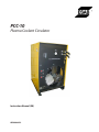
ESAB PCC-10 Plasma Coolant Circulator User manual
- Category
- Welding System
- Type
- User manual
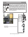
ESAB PCC-10 Plasma Coolant Circulator is a reliable and efficient solution for cooling electric arc cutting and welding equipment, offering precise temperature control and a range of safety features. Its compact design allows for easy installation, and its durable construction ensures longevity in demanding industrial environments. The unit's adjustable by-pass valve and high-capacity pump deliver optimal coolant flow, while the copper tubing and aluminum finned radiator provide excellent heat dissipation.
ESAB PCC-10 Plasma Coolant Circulator is a reliable and efficient solution for cooling electric arc cutting and welding equipment, offering precise temperature control and a range of safety features. Its compact design allows for easy installation, and its durable construction ensures longevity in demanding industrial environments. The unit's adjustable by-pass valve and high-capacity pump deliver optimal coolant flow, while the copper tubing and aluminum finned radiator provide excellent heat dissipation.


-
 1
1
-
 2
2
-
 3
3
-
 4
4
-
 5
5
-
 6
6
-
 7
7
-
 8
8
-
 9
9
-
 10
10
-
 11
11
-
 12
12
-
 13
13
-
 14
14


ESAB PCC-10 Plasma Coolant Circulator User manual
- Category
- Welding System
- Type
- User manual
ESAB PCC-10 Plasma Coolant Circulator is a reliable and efficient solution for cooling electric arc cutting and welding equipment, offering precise temperature control and a range of safety features. Its compact design allows for easy installation, and its durable construction ensures longevity in demanding industrial environments. The unit's adjustable by-pass valve and high-capacity pump deliver optimal coolant flow, while the copper tubing and aluminum finned radiator provide excellent heat dissipation.
Ask a question and I''ll find the answer in the document
Finding information in a document is now easier with AI
Related papers
-
ESAB PCC-10 Plasma Coolant Circulator User manual
-
ESAB m3® Plasma User manual
-
-
-
-
-
-
-
-
Other documents
-
 Thermal Comfort 3000 User manual
-
Lincoln Electric Magnum Cooler 10-I User manual
-
-
-
 Thermal Arc ULTIMA 150 User manual
-
Lincoln Electric Cool Arc 40 Operating instructions
-
-
Lincoln Electric Cool Arc 55 S Operating instructions
-
-

