Mitsubishi Electric AC Servos Operating instructions

Type
Operating instructions
本書は,再生紙を使用しています。
お断りなしに仕様を変更することがありますのでご了承ください。
IB( )0300077-AK(1803)IP
20183月作成
形 名
形 名
コード
J3シリーズ
三菱電機 汎用 ACサーボ
ACサーボを安全にお使いいただくために
AK
本社機器営業部
北海道支社
東北支社
関越支社
新潟支店
神奈川支社
北陸支社
中部支社
豊田支店
関西支社
中国支社
四国支社
九州支社
(03)3218-6740
(011)212-3793
(022)216-4546
(048)600-5835
(025)241-7227
(045)224-2623
(076)233-5502
(052)565-3326
(0565)34-4112
(06)6486-4120
(082)248-5445
(087)825-0055
(092)721-2251
東京都千代田区丸の内2-7-3(東京ビル)
札幌市中央区北二条西4-1(北海道ビル)
仙台市青葉区花京院1-1-20(花京院スクエア)
さいたま市中央区新都心11-2(明治安田生命さいたま新都心ビ)
新潟市中央区東大通2-4-10(日本生命ビル)
横浜市西区みなとみらい2-2-1(横浜ランドマークタワー)
金沢市広岡3-1-1(金沢パークビル)
名古屋市中村区名駅3-28-12(大名古屋ビルヂング)
豊田市小坂本町1-5-10(矢作豊田ビル)
大阪市北区大深町4-20(グランフロント大阪タワーA)
広島市中区中町7-32(ニッセイ広島ビ
)
高松市寿町1-1-8(日本生命高松駅前ビル)
福岡市中央区天神2-12-1(天神ビル)
100-8310
060-8693
980-0013
330-6034
950-8504
220-8118
920-0031
450-6423
471-0034
530-8206
730-8657
760-8654
810-8686
100-8310  東京都千代田区丸の内2-7-3 (東ビル)
お問い合わは下記へうぞ
三菱電機株式会社
インターネットによる情報サービス「三菱電機FAサイト」
三菱電機FAサイトでは、製品や事例などの技術情報に加え、トレーニングスクール情報や
各種お問い合わせ窓口をご提供しています。また、メンバー登録いただくとマニュアルや
CADデータ等のダウンロード、eラーニングなどの各種サービスをご利用いただけます。
三菱電機 FA
お問い合わせの際には、今一度電話番号をお確かめの上、お掛け間違いのないようお願い致します
電話技術相談窓口
受付時間
1
月曜~金曜 9:0019:00、土曜・日曜・祝日 9:0017:00
サーボ/位置決めユニット/
シンプルモーションユニット/
モーションコントローラ/
センシングユニット/
組込み型サーボシステム
コントローラ
MELSERVOシリーズ
位置決めユニット(MELSEC iQ-R/Q/L/A シリーズ)
シンプルモーションユニット(MELSEC iQ-R/iQ-F/Q/Lシリーズ)
モーションCPU(MELSEC iQ-R/Q/Aシリーズ)
センシングユニット(MR-MTシリーズ)
シンプルモーションボー
C言語コントローラインタフェースユニット(Q173SCCF)/ポジションボード
MELSOFT MTシリーズ/MRシリーズ/EMシリーズ
052-712-6607
対 象 機 種
1: 春季・夏季・年末年始の休日を除
三菱電機株式会社
MR-J3-10□~MR-J3-22K□
MR-J3-10□1~MR-J3-40□1
MR-J3-60□4~MR-J3-22K□4
MR-J3-DU30K□・MR-J3-DU37K□
MR-J3-DU30K□4~MR-J3-DU55K□4
MR-J3-CR55K(4)
第1章 はじめに
1.1 マニュアルの紹介
MELSERVO-J3シリーズを安全に使用するために,各技術資料集を熟読してください。
初めてMELSERVO-J3シリーズをお使いいただく場合,次のマニュアルが必要です。
これらをすべて熟読し,MELSERVO-J3シリーズを安全にご使用ください。
サーボアンプ
(ドライブユニット)
マニュアル
MR-J3-A
(MR-J3-DUA)
MR-J3-B
(MR-J3-DUB)
MR-J3-B
-RJ004
MR-J3-B
-RJ006
MR-J3-T
MR-J3-T/
MR-J3-D01
MR-J3-BS
MR-J3-B
-RJ080W
サーボモータ技術資料集 第2集 SH(名)030040
MR-J3-□Aサーボアンプ技術資料集
SH(名)030037
MR-J3-□Bサーボアンプ技術資料集
SH(名)030050
MR-J3-□B-RJ004技術資料集 SH(名)030053
MR-J3-□B-RJ006サーボアンプ技術資料集
SH(名)030055
MR-J3-□Tサーボアンプ技術資料集
SH(名)030057
MR-J3-□T/MR-J3-D01サーボアンプ技術資料集
SH(名)030060
MR-J3-□BSサーボアンプ技術資料集
SH(名)030083
MR-J3-□B-RJ080W技術資料集 SH(名)030078
1.2 梱包内容
梱包を開いて,お客様が注文されたコンバータユニット・サーボアンプ(ドライブユニット)であるか,定格名板の
記載内容で確認してください。
(1) コンバータユニット
梱包品 数量 梱包品 数量
コンバータユニット 1 デジタル入出力用コネクタ 1
吊りボルト 2
MELSERVO-J3シリーズACサーボを安全にお
使いいただくために(本書)
1
電磁接触器制御用コネクタ 1
(2) サーボアンプ(ドライブユニット)
梱包
サー
アン
(
ドライ
ユニット
)
1
サー
アン
プ電
源コ
クタ CNP1用・CNP2用・CNP3用
(
1
)
1
CC-Link通
クタ CN1用
(
3
)
1
サー
アン
プ電
源コ
クタ用
結線
レバー
(
1
)
1
(
4
)
2
吊り
ルト
(
4
)
2
MELSERVO-J3シリー
ACサーボを安全にお使いいただくために(本書)
1
サー
アン
正面カバー取
けねじ
(
M4×14
)
(
2
)
1
サー
アン
プ冷却
ファンカバー取
けねじ
(
M4×40
)
(
2
)
2
短絡
クタ CN8用
(
5
)
1
注 1. 3.5kW以下に付属しています。
2. 11k~22kWに付属しています。
3. MR-J3-□Tサーボアンプに付属しています。
4. 30kW以上に付属しています。
5. MR-J3-□BSサーボアンプに付属しています。
1.3 形名の構成
(
1
)
定格名板
製造年月
形名
容量
適用電源
定格出力電
製造番号
KC認証番号
原産国
(2) 形名
ここでは形名の内容を説明しています。すべての記号の組合せが存在するものではありません。
(a) コンバータユニット
シリーズ名
MR-J3-CR□□
電源記号
三相AC200Vなし
三相AC400V4
適用ドライブユニット容量(kW)
30~55
記号
55K
適用ドライブユニット容量
電源
(b) サーボアンプ(ドライブユニット)
電源記号
MR-J3-□□□□□-□□
単相AC100~120V
三相AC200~230V
単相AC200~230V
なし
1
三相AC380~480V4
シリーズ名
定格出力
電源
対応
汎用インタフェース
SSCNETⅢ
記号
A
B
T
CC-Link対応
位置決め機能内蔵
対応
注. 30kW以上はドライブユニットになります。
45
7
11
15
22
30
37
5
55
定格出力[kW]定格出力[kW]
200
記号 記号
10
350
0.1
3.5
20
500
0.2
40
700
0.4
60
11K
0.6
70
15K
0.75
100
22K
1
2
(注)DU30K
(注)DU37K
(注)DU45K
(注)DU55K
N:管理区分
S:三菱電機ドライブセーフティ対応
ソフトウエア特殊仕様
空白,Jn,SnまたはUn(nは00~999の数字)
ハードウエア特殊仕様
空白または2~5文字の英数字(RJ,ED,PX,RU,RZなど)
第2章 CEマーキングへの対応
2.1 CEマーキングとは
CEマーキングとは,欧州連合地域で販売される指定製品に表示を義務付けられているCEマークを表示することです。
要求事項(指令)を満たしている製品には,CEマークを表示しなければなりません。CEマーキングは,欧州連合地域で
販売するサーボが組み込まれた機械および装置も対象になります。CEマーキングの適合宣言のコピーが必要な場合,
営業窓口にお問合せください。
(1) EMC指令
EMC指令は,コンバータユニット・サーボアンプ(ドライブユニット)も対象であり,EMC指令に適合するように設
計しています。また,このコンバータユニット,サーボアンプ(ドライブユニット)を組み込んだ機械・装置も対
象になります。このコンバータユニット,サーボアンプ(ドライブユニット)を組み込んだ機械・装置をEMC指令に
適合させるために,EMCフィルタを使用する必要があります。具体的なEMC指令対処方法はEMC設置ガイドライン(IB
(名)67303)を参照してください。
(2) 低電圧指令
低電圧指令は,コンバータユニット・サーボアンプ(ドライブユニット)も対象であり,低電圧指令に適合するよ
うに設計しています。
(3) 機械指令
コンバータユニット・サーボアンプ(ドライブユニット)は機械を構成する主要コンポーネントです。
このコンバータユニット・サーボアンプ(ドライブユニット)を組み込んだ機械が機械指令に適合していること
を宣言されるまでは,機械を使用させないでください。
MR-J3-□Sサーボアンプは機械指令(Machinery directive)に適合する安全コンポーネントです。
(4) RoHS指令
コンバータユニット・サーボアンプ(ドライブユニット)は,RoHS指令に適合しています。
2.2 適合のために
各ユニットを据え付ける前に外観検査を行ってください。さらに,最終的に機械として性能検査を実行し,検査記
録を保管してください。
(1) 使用するコンバータユニット・サーボアンプ(ドライブユニット)・サーボモータ
コンバータユニット・サーボアンプ(ドライブユニット)・サーボモータは標準品を使用してください。
コンバータユニット:MR-J3-CR55K・MR-J3-CR55K4
サーボアンプMR-J3-10□~MR-J3-22K□・MR-J3-10□1~MR-J3-40□1
MR-J3-60□4~MR-J3-22K□4
ドライブユニット MR-J3-DU30K□・MR-J3-DU37K□・MR-J3-DU30K□4~MR-J3DU55K□4
サーボモータHF-MP□・HF-KP□・HF-SP□・HF-SP□4・HC-RP□・HC-UP□
HC-LP□・HA-LP□・HA-LP□4・HF-JP□・HF-JP□4
(2) 構成
サーボアンプ内では制御回路と主回路は安全に分離されています。
M
MCMCCB
制御盤
ノーヒューズ
遮断器
電磁接触器
強化絶縁型
DC24V
電源
サーボアンプ
(ドライブユニット)
サーボモータ
(注)コンバータユニット
注. 22kW以下のサーボアンプにはありません。
(3) 環境
(a) コンバータユニット・サーボアンプ(ドライブユニット)は,EN 60664-1に規定されている汚染度2または1の
環境下で使用してください。 そのためには,水・油・カーボン・塵埃などが入り込まない構造(IP54)の制御
盤に設置してください。
(b) 次の環境条件で使用してください。
項目 環境条件 項目 環境条件
(注1)
周囲温度
運転
(注2)
0℃~55℃
周囲湿度 運転・保存・輸送 90%RH以下
標高
運転・保存 1000m以下
保存・輸送 -20℃~65℃ 輸送 10000m以下
注 1. 周囲温度は制御盤内部の温度です。
2. 200V級の3.5kW以下と100V級の400W以下のサーボアンプは,密着取付けが可能です。この場合,周囲温度を0~45℃
にするか,実効負荷率75%以下で使用してください。
(4) 電源
(a) コンバータユニット・サーボアンプ(ドライブユニット)は中性点が接地されたスター結線の電源においてEN
60664-1に規定されている過電圧カテゴリⅢの条件で使用できます。ただし,400V系の中性点を使用して単
相入力で使用する場合は電源入力部に強化絶縁トランスが必要です。
(b) インタフェース用の電源は必ず,入出力が強化絶縁されたDC24Vの外部電源を使用してください。
(5) 接地
(a) 感電防止のためコンバータユニット・サーボアンプ(ドライブユニット)の保護接地(PE)端子( マークのつ
いた端子)を制御盤の保護接地(PE)に必ず接続してください。
(b) 保護接地(PE)端子に接地用電線を接続するとき,共締めしないでください。接続は必ず一端子に一電線にし
てください。
PE端子 PE端子
(c) 漏電遮断器を使用する場合でも,感電防止のためサーボアンプの保護接地(PE)端子は必ず接地してくださ
い。
(6) 配線
(a) コンバータユニット・サーボアンプ(ドライブユニット)の端子台に接続する電線は隣の端子と接触しないよ
うに,必ず絶縁チューブ付きの圧着端子を使用してください。
圧着端子
絶縁チューブ
電線
(b) サーボモータ側の電源用コネクタは,EN対応品を使用してください。オプション品としてEN対応電源コネク
タセットを用意しています。
(c) コンバータユニット・サーボアンプ(ドライブユニット)は必ず金属製の制御盤内に設置してください。
(7) 周辺機器・オプション
(a) ノーヒューズ遮断器・電磁接触器はMR-J3-□サーボアンプ技術資料集記載機種のEN準拠品を使用してくださ
い。タイプBの漏電遮断器(RCD)を使用してください。使用しない場合は,二重絶縁または強化絶縁でサー
ボアンプと他の装置の間に絶縁を確保するか,主電源とサーボアンプ(ドライブユニット)の間にトランスを
入れてください。
(b) MR-J3-□サーボアンプ技術資料集記載の電線は次の条件におけるサイズです。それ以外の条件で使用する場
合はEN 60204-1の表6および付属書Dに従ってください。
・周囲温度:40℃
・被覆 :PVC(ポリ塩化ビニル)
・壁面または開放ケーブルトレイに設置
(c) ノイズ対策用としてはEMCフィルタを使用してください。
(8) EMCテストの実施
コンバータユニット・サーボアンプ(ドライブユニット)を組み込んだ機械・装置のEMCテストは,使用する環
境・電気機器の仕様を満足する状態で電磁両立性(イミュニティ・エミッション)基準に到達していることが必要
です。コンバータユニット・サーボアンプ(ドライブユニット)に関するEMC指令対処方法についてはEMC設置ガイド
ライン(IB(名)67303)を参照してください。
MR-J3シリーズは,家庭向きの建物に供給される低電圧の公衆通信回線で使用することを想定していません。その
ような回線で使用すると,無線周波数干渉が発生する恐れがあります。設置者は,推奨される軽減機器を含む設
置および使用のためのガイドを提供しなければなりません。
第3章 韓国対応
本製品は電波法 (KCマーク) に準拠しています。本製品を使用する場合,下記にご注意ください。
기기는 업무용 (A) 전자파적합기기로서 판매자 또는 사용자는 점을 주의하시기 바라며, 가정외의 지역에서
사용하는 것을 목적으로 합니다.
(本製品は業務用 (A級) 電磁波対応機器であり,販売者または使用者はこの点に注意し,家庭以外で使用すること。)
第4章 UL/cUL規格への適合
このサーボアンプは,UL 508C,CSA C22.2 №14規格に適合するように設計しています。
表・図中に記載しているサーボアンプの形名については1.3節(2)を参照してください。
(1) 使用するコンバータユニット・サーボアンプ(ドライブユニット)・サーボモータ
コンバータユニット・サーボアンプ(ドライブユニット)・サーボモータは標準品を使用してください。
サーボ
アンプ
サーボモータ
HF-KP HF-MP HF-SP HC-RP HC-UP HC-LP HA-LP HF-JP
MR-J3-10□(1) 053・13 053・13
MR-J3-20□(1) 23 23
MR-J3-40□(1) 43 43
MR-J3-60□ 51・52 52 53
MR-J3-70□ 73 73 72
MR-J3-100□ 81・102 102 73・103
MR-J3-200□
121・201・
152・202
103・153 152 152 153・203
MR-J3-350□ 301・352 203 202 202 353
MR-J3-500□ 421・502 353・503 352・502 302 502 503
MR-J3-700□ 702 601・701M・702 703
MR-J3-11K□
801・12K1・
11K1M・11K2
903・11K1M
MR-J3-15K□
15K1・15K1M・
15K2
15K1M
MR-J3-22K□
20K1・25K1・
22K1M・22K2
サーボ
アンプ
サー
モータ
コンバータ
ユニット
ドライブ
ユニット
サーボモータ
HA-LP
HF-SP H
A
-LP HF-JP
M
R
-J3-60□4 524 534
MR-J3-CR55K
M
R
-J3-DU30
K
30K1・30K1M・30K2
M
R
-J3-100□4 1024 734・1034 M
R
-J3-DU37
K
37K1・37K1M・37K2
M
R
-J3-200□4 1524・2024 1534・2034
MR-J3-CR55K4
M
R
-J3-DU30
K
□4 25K14・30K14・30K1M4・30K24
M
R
-J3-350□4 3524 3534 M
R
-J3-DU37
K
□4 37K14・37K1M4・37K24
M
R
-J3-500□4 5024 5034 M
R
-J3-DU45
K
□4 45K1M4・45K24
M
R
-J3-700□4 7024 6014・701M4 7034 M
R
-J3-DU55
K
□4 50K1M4・55K24
MR-J3-11K□4
8014・12K14・
11K1M4・11K24
9034・11K1M4
MR-J3-15K□4
15K14・15K1M4・
15K24
15K1M4
MR-J3-22K□4
20K14・22K1M4・
22K24
(2) 設置
注意
●11kW~22kWのサーボアンプに付属の回生抵抗器は保護カバーがないため,抵抗
器(配線ねじ締め部を含む)に触れた場合,火傷および感電の恐れがあります。
なお,次の理由により,電源遮断後でも母線電圧が放電し,温度が下がるま
での間は注意してください。
・非常に高熱になるため,熱が冷めず火傷の恐れがあります。
・サーボアンプのコンデンサが充電されているため,感電の恐れがあります。
MR-J3シリーズは盤内据付けの製品です。盤の容積は,各ユニットの合計容積の150%以上あり,盤内温度が55℃
を超えないように設計してください。コンバータユニット・サーボアンプ(ドライブユニット)は必ず金属製の制
御盤内に設置してください。環境はオープンタイプ(UL 50)と過電圧カテゴリⅢ以下で使用してください。コン
バータユニット・サーボアンプ(ドライブユニット)の設置には汚染度2以下にしてください。接続用の電線には,
銅製を使用してください。
(3) 短絡電流定格 (SCCR)
このサーボアンプは,最大電圧500V,対象電流100kA以下の回路での使用に適していることを短絡試験で確認し
ています。
(4) フランジ
サーボモータは次のフランジサイズまたは同等以上の放熱効果のあるものに取り付けてください。
フランジ
サイズ[mm]
モータ
HF-MP・HF-KP HF-SP HC-RP HC-UP HC-LP H
A
-LP HF-JP
250×250×6 053・13・23
250×250×12 43
51・81
52(4)~152(4)
103~203 52~152 53(4)~203(4)
300×300×12 73
300×300×20
121・201
202(4)・352(4)
202・302
550×550×30 353・503 72・152 353
(
4
)
・503
(
4
)
650×650×35
301・421
502(4)・702(4)
202~502
601
(
4
)
~12K1
(
4
)
701M(4)~15K1M(4)
502~22K2
11K24~22K24
703(4)・903(4)
11K1M(4)・15K1M4(4)
950×950×35
15K1
(
4
)
~37K1
(
4
)
22K1M~37K1M
22K1M4~50K1M4
30K2・37K2
30K24~55K24
(5) コンデンサ放電時間
コンデンサ放電時間は次のとおりです。安全のために電源OFF後,15分間(30kW以上の場合は20分間)は充電部分
に触らないでください。
サーボアンプ 放電時間[min] サーボアンプ 放電時間[min]
MR-J3-10□・20□ 1 MR-J3-350□4・500□(4)・700□(4) 10
MR-J3-40□・60□(4)・10□1・20□1 2 MR-J3-11K□(4) 4
MR-J3-70□ 3 MR-J3-15K□(4) 6
MR-J3-40□1 4 MR-J3-22K□(4) 8
MR-J3-100□(4) 5
MR-J3-DU30K□・DU37K□・DU30K□4・
DU37K□4・DU45K□4・DU55K□4
20
MR-J3-200□(4)・350□ 9
(6) 過負荷保護特性
サーボアンプは,サーボモータ,サーボアンプ,サーボモータ動力線を過負荷から保護するための電子サーマ
ルを装備しています。電子サーマルの作動特性を以下に示します。昇降軸のようにアンバランストルクが発生す
る機械では,アンバランストルクが定格トルクの70%以下で使用することを推奨します。サーボアンプ密着取付
けは,周囲温度を0~45℃にするか,実効負荷率75%以下で使用してください。
MR-J3シリーズサーボアンプにはサーボモータ過負荷保護機能が内蔵されています。(サーボアンプ定格電流の
115%を基準(full load current)に定めています。)
[s]
1000
100
10
0.1
0
サーボロック時
運転時
1
200100 300 350
(注2)負荷率[%]
[s]
1000
100
10
0.1
0
サーボロック時
運転時
1
200100 300 350
(注2)負荷率[%]
[s]
1000
100
10
0.1
0 200 300
負荷率[%]
100
サーボロック時
運転時
1
MR-J3-10□(1)
MR-J3-20□(1)・MR-J3-40□(1)
MR-J3-60□(4)~MR-J3-100□(4)
MR-J3-200□(4)・MR-J3-350□(4)
[s]
10000
1000
100
10
1
0200100
300
運転
サーボロック
負荷率[%]
[s]
10000
1000
100
10
1
0200100
300
サーボロック
運転
負荷率[%]
[s]
10000
1000
100
10
1
0 200 250100
(注1)サーボロック
負荷率[%]
運転
MR-J3-500□(4)・MR-J3-700□(4) MR-J3-11K□(4)~MR-J3-22K□(4) MR-J3-DU30K□(4)・MR-J3-DU37K□(4)
MR-J3-DU54K□4・MR-J3-DU55K□4
コンバータユニットMR-J3-CR55K(4)
注 1. サーボロック時のサーマル保護特性は,MR-J3-CR55K(4)の場合はありません。
2. 負荷率300~350%の値はHF-KPサーボモータの最大トルクを350%にした場合です。
(7) 過熱保護
サーボモータの過熱は,サーボアンプでは検出されません。
サーボモータには過熱保護が必要です。適切な接続については第3章(12)を参照してください。
(8) 電線選定例
UL/cUL規格に対応する場合,配線にはUL認定の60/75℃定格の銅電線を使用してください
次の表に60℃定格の撚線[AWG]と圧着端子選定記号を示します。( )内は75℃定格の場合です。
サーボアンプ
(ドライブユニット)
コンバータ
ユニット
(
3
)
[
AWG
]
L1・L2・L3
L11・L21
U・V・W・P
1・P2
P・P
2・C
M
R
-J3-10□
(
1
)
~40□
(
1
)
60□・70□
14(14)
16(16)
(注4)14(14)
14(14)
M
R
-J3-100□・200□
M
R
-J3-350□ 12
(
12
)
12
(
12
)
(
1
)
M
R
-J3-500□ 10
(
10
)
:a
(
a
)
16(16):h(h)
10
(
10
)
:a
(
a
)
14
(
14
)
:g
(
g
)
(
1
)
M
R
-J3-700□ 8
(
8
)
:b
(
b
)
8
(
8
)
:b
(
b
)
12
(
12
)
:a
(
a
)
(
1
)
M
R
-J3-11
K
6
(
6
)
:c
(
c
)
16(16):g(g)
4
(
4
)
:d
(
c
)
10(10):j(j)
(
1
)
M
R
-J3-15
K
4
(
4
)
:d
(
d
)
2
(
3
)
:e
(
d
)
(
1
)
M
R
-J3-22
K
1/0
(
1
)
:f
(
p
)
-
(
1
)
:-
(
p
)
10
(
10
)
:k
(
k
)
(
1
)
M
R
-J3-DU30
K
MR-J3-CR55K
-
(
1
)
:-
(
t
)
14(14) -(2/0):-(u) 10(10):r(r)
(
1
)
M
R
-J3-DU37
K
-
(
2/0
)
:-
(
u
)
M
R
-J3-60□4
14(14) 16(16) 14(14) 14(14) M
R
-J3-100□4
M
R
-J3-200□4
M
R
-J3-350□4 14
(
14
)
:g
(
g
)
16(16):h(h)
14
(
14
)
:g
(
g
)
14(14):g(g)
(
1
)
M
R
-J3-500□4
10(12):a(a)
10
(
12
)
:a
(
a
)
(
1
)
M
R
-J3-700□4 10
(
10
)
:a
(
a
)
(注1)MR-J3-11K□4 8(10):l(j)
16(16):g(g)
8(8):l(l) 12(12):j(j)
(注1)MR-J3-15K□4 6(8):c(l) 4(6):d(c) 10(10):j(j)
(注1)MR-J3-22K□4 6(6):m(m) 4(6):n(m) 10(10):k(k)
(注1)MR-J3-DU30K□4
MR-J3-CR55K4
3(4):s(s)
14(14)
2(3):p(n)
10(10):r(r)
(注1)MR-J3-DU37K□4 2(2):t(s) 1(2):p(n)
(注1)MR-J3-DU45K□4
-(2):-(t) -(1/0):-(t)
(注1)MR-J3-DU55K□4
サーボアンプ
(ドライブユニット)
コンバータ
ユニット
撚線[AWG]
B1・B2 BU・BV・BW OHS1・OHS2
MR-J3-10□(1)~40□(1)・
60□・70□
16(16)
MR-J3-100□・200□
MR-J3-350□
(注1)MR-J3-500□
(注1)MR-J3-700□ (注2)14(14) (注2)16(16)
(注1)MR-J3-11K□
14(14) 16(16)
(注1)MR-J3-15K□
(注1)MR-J3-22K□
(注1)MR-J3-DU30K□
MR-J3-CR55K
(注1)MR-J3-DU37K□
MR-J3-60□4
16(16)
MR-J3-100□4
MR-J3-200□4
MR-J3-350□4
(注1)MR-J3-500□4
(注1)MR-J3-700□4 (注2)14(14) (注2)16(16)
(注1)MR-J3-11K□4
14(14)
16(16)
(注1)MR-J3-15K□4
(注1)MR-J3-22K□4
(注1)MR-J3-DU30K□4
MR-J3-CR55K4 16(16)
(注1)MR-J3-DU37K□4
(注1)MR-J3-DU45K□4
(注1)MR-J3-DU55K□4
注 1. 端子台へ接続するときは,必ず端子台に付属しているねじを使用してください。
2. 冷却ファン付きサーボモータの場合です。
3. 表中のアルファベットは圧着工具を示します。圧着端子・適合工具は推奨圧着端子表を参照してください。
4. HF-MP・KPサーボモータとの配線にはMR-PWS1CBL(オプション)を使用してください。延長が必要な場合はAWG14電線を使用してく
ださい。
表. 推奨圧着端子
記号
サーボアンプ側圧着端子
メーカ名
(注2)圧着端子
適用工具
本体 ヘッド ダイス
a FVD5.5-4 YNT-1210S
JST
(注1)b 8-4NS YHT-8S
c FVD14-6
YF-1・E-4 YNE-38
DH-112・DH-122
d FVD22-6 DH-113・DH-123
(注1)e 38-6
YPT-60-21
TD-112・TD-124
YF-1・E-4 YET-60-1
(注1)f R60-8
YPT-60-21
TD-113・TD-125
YF-1・E-4 YET-60-1
g FVD2-4
YNT-1614
h FVD2-M3
j FVD5.5-6
YNT-1210S
k FVD5.5-8
l FVD8-6
YF-1・E-4 YNE-38
DH-111・DH-121
m FVD14-8 DH-112・DH-122
n FVD22-8 DH-113・DH-123
(注1)p R38-8
YPT-60-21
TD-112・TD-124
YF-1・E-4 YET-60-1
q FVD2-6 YNT-1614
r FVD5.5-10 YNT-1210S
s FVD22-10 YF-1・E-4 YNE-38 DH-113・DH-123
(注1)t R38-10
YPT-60-21
TD-112・TD-124
YF-1・E-4 YET-60-1
(注1)u R60-10
YPT-60-21
TD-113・TD-125
YF-1・E-4 YET-60-1
注 1. 圧着部分を絶縁チューブで被ってください。
2. 圧着端子はサイズによって取付けできない場合がありますので,必ず推奨品または同等品をお使いください。
(9) 各端子の締付けトルク
注意
● 電線を既定の方法および規定のトルクで確実に接続してください。サーボモー
タの予期しない動きの原因になります。
サーボアンプ
締付けトルク[N・m]
L
1
L
2
L
3
N P
1
P
2
P C L
11
L
21
U V W PE
MR-J3-10□(1)~40□(1)・
60□~100□・60□4・
100□4・200□(4)
1.2
MR-J3-200□-RT・350□ 0.6 0.6
MR-J3-350□4・500□(4)・
700□(4)
1.2 0.8 1.2
MR-J3-11K□(4)・15K□(4) 3.0
3.0
1.2
3.0
MR-J3-22K□(4) 6.0 6.0 6.0
ドライブユニット
コンバータユニット
締付けトルク[N・m]
L
1
L
2
L
3
P
1
C L+ L- L
11
L
21
U V W PE
MR-J3-DU30K□・DU37K□
DU45K□4・DU55K□4
3.0 1.2
12.0
MR-J3-DU30K□・DU37K□4 6.0
MR-J3-CR55K(4) 12.0 12.0
(10)配線保護について
アメリカ合衆国内に設置する場合,分岐回路の保護はNational Electrical Codeおよび現地の規格に従って実
施してください。
カナダ国内に設置する場合,分岐回路の保護はCanada Electrical Codeおよび州の規格に従って実施してくだ
さい。
(11)オプション・周辺機器
UL/cUL規格対応品を使用してください。
次の表に示すノーヒューズ遮断器(UL489認定MCCB)またはヒューズ(T級)を使用してください。
サーボアンプ
(コンバータユニット・ドライブユニット)
ノーヒュー
ズ遮
(
)
ヒュー
電圧AC
[
V
]
[
A
]
電圧AC
[
V
]
M
R
-J3-10□
(
1
)
・20□ 50
A
フレーム5
A
10
M
R
-J3-40□・20□1 50
A
フレーム10
A
15
M
R
-J3-60□~100□・40□1 50
A
フレーム15
A
20
M
R
-J3-200□ 50
A
フレーム20
A
40
M
R
-J3-350□ 50
A
フレーム30
A
70
M
R
-J3-500□ 50
A
フレーム50
A
240
125
300
M
R
-J3-700□ 100
A
フレーム75
A
150
M
R
-J3-11
K
100
A
フレーム100
A
200
M
R
-J3-15
K
225
A
フレーム125
A
250
M
R
-J3-22
K
225
A
フレーム175
A
350
MR-J3-CR55K
M
R
-J3-DU30
K
400
A
フレーム250
A
500
M
R
-J3-DU37
K
400
A
フレーム300
A
600
M
R
-J3-60□4 50
A
フレーム5
A
10
M
R
-J3-100□4 50
A
フレーム10
A
15
M
R
-J3-200□4 50
A
フレーム15
A
25
M
R
-J3-350□4 50
A
フレーム20
A
35
M
R
-J3-500□4 50
A
フレーム30
A
50
M
R
-J3-700□4 50
A
フレーム40
A
65
M
R
-J3-11
K
□4 60
A
フレーム60
A
600Y/347 100 600
M
R
-J3-15
K
□4 100
A
フレーム75
A
150
M
R
-J3-22
K
□4 225
A
フレーム125
A
175
M
R
-J3-DU30
K
□4 225
A
フレーム125
A
250
MR-J3-CR55K4
M
R
-J3-DU37
K
□4 225
A
フレーム150
A
300
M
R
-J3-DU45
K
□4 225
A
フレーム175
A
400
M
R
-J3-DU55
K
□4 400
A
フレーム225
A
450
. 力
率改善
リアクトル
を使
用し
い場
(12)構成図
UL/cUL規格対応のための代表的な構成図を示します。接地端子の配線は省略しています。
(a) MR-J3-22K□(4)以下
電源
MCCB
または
ヒューズ
L
1
/L
2
/L
3
L
11
CN5
CN3
CN1
CN2
CN6
U/V/W/PE
指令装置
検出器ケーブル
制御盤側
機械側
サーボモータ
検出器
サーボアンプ
MCCB
または
ヒューズ
L
21
保護装置(サー
マル保護)(注2)
(注1)
(b) MR-J3-DU30K□(4)以上
電源
MCCB
または
ヒューズ
L+
L+
L-
CN5
CN3
CN1
CN2
CN6
U/V/W/PE
指令装置
検出器ケーブル
制御盤側
機械側
サーボモータ
検出器
L
1
コンバータユニット ドライブユニット
MCCB
または
ヒューズ
(注1)
MCCB
または
ヒューズ
(注1)
L
2
L
3
L
11
L
21
L
11
L
21
L-
保護装置(サー
マル保護)(注2)
注 1. L1とL11の電線サイズが同一の場合,MCCBまたはヒューズは不要です。
2. サーボモータの過熱保護はサーマルセンサなどを使用してお客様で実施してください。
図中の( )で示された制御回路コネクタは( )で示された主回路から安全に切り離されています。
第5章 点検
危険
● 点検などで機械の可動部に近づく必要がある場合,電源の遮断を確認するなど,
安全を確保してください。事故の原因になります。
● 感電の恐れがあるため,保守・点検は,電源OFF後,15分以上(30kW以上の場合,
20分以上)経過し,チャージランプが消灯したのち,テスタなどでP()-N(-)
間(30kW以上の場合L+-L-間)の電圧を確認してから行ってください。なお,
チャージランプの消灯確認は必ずサーボアンプ(コンバータユニット)の正面か
ら行ってください。
● 感電の恐れがあるため,専門の技術者以外は点検を行わないでください。また,
修理・部品交換はお近くの三菱電機システムサービスにご連絡ください。
注意
● サーボアンプ(ドライブユニット)の絶縁抵抗測定(メガテスト)を行わないでく
ださい。故障の原因になります。
● お客様で分解・修理を行わないでください。
(1) 点検
定期的に次の点検を行うことを推奨します。
(a) 端子台のねじに緩みがないか。緩んでいたら増締めしてください。
(b) ケーブル類に傷・割れはないか。特に稼動する場合は,使用条件に応じて定期点検を実施してください。
(c) サーボアンプにコネクタが正しく装着されているか。
(d) コネクタから電線が抜けていないか。
(e) サーボアンプに埃がたまっていないか。
(f) サーボアンプから異音が発生していないか。
(2) 寿命
部品の交換寿命は次のとおりです。ただし,使用方法や環境条件により変動しますので,異常を発見したら交
換する必要があります。また,オイルミスト・粉塵などの多い雰囲気で使用する場合は,3ヶ月ごとに清掃・点検
を実施してください。
部品交換は三菱電機システムサービスで承ります。
寿命
の目
コンバータユニット・
サーボアンプ
(ドライブユニット)
平滑コン
ンサ 10
リレー
入回
および非
常停
止回
10万回
冷却
ファン 1万~3万
(
2~3
)
置用バッテリ M
R
-J3-□サー
アン
術資料集参
(a) 平滑コンデンサ
平滑コンデンサはリップル電流などの影響により特性が劣化します。コンデンサの寿命は,周囲温度と使
用条件に大きく左右されます。空調された通常の環境条件(周囲温度40℃以下)で連続運転した場合,10年で
寿命になります。
(b) リレー類
開閉電流による接点摩耗で接触不良が発生します。電源容量により左右されますが電源投入回数および非
常停止回数10万回で寿命になります。
(c) コンバータユニット・サーボアンプ(ドライブユニット)冷却ファン
冷却ファンのベアリング寿命で1万~3万時間です。したがって,連続運転の場合通常2~3年目を目安とし
て,ファンごと交換する必要があります。
また,点検時に異常音,異常振動を発見した場合も交換する必要があります。
第6章 アラーム・警告
アラーム・警告の詳細については,各サーボアンプ技術資料集を参照してください。
第7章 準拠規格
MR-J3サーボアンプは次の規格に準拠しています。
IEC/EN/KN 61800-3/GB 12668.3
安全上の注意
ご使用の前に必ずお読みください。
据付け,運転,保守・点検の前に必ず本書および付属書類をすべて熟読し,正しくご使用ください。
機器の知識,安全の情報および注意事項のすべてについて習熟してからご使用ください。
本書では,安全注意事項のランクを「危険」,「注意」として区分してあります。
危険
取扱いを誤った場合に,危険な状況が起こりえて,死亡または重傷を受
ける可能性が想定される場合。
注意
取扱いを誤った場合に,危険な状況が起こりえて,中程度の傷害や軽傷
を受ける可能性が想定される場合および物的損害だけの発生が想定さ
れる場合。
なお, 注意に記載した事項でも,状況によっては重大な結果に結びつく可能性があります。いず
れも重要な内容を記載していますので必ず守ってください。
禁止,強制の絵表示の説明を次に示します。
禁止(してはいけないこと)を示します。例えば,「火気厳禁」の場合は
になります。
強制(必ずしなければならないこと)を示します。例えば,接地の場合は
になります。
本書では,物的損害に至らないレベルの注意事項や別機能などの注意事項を「ポイント」として区分
してあります。
お読みになったあとは,使用者がいつでもみられるところに必ず保管してください。
1.感電防止のために
危険
・感電の恐れがあるため,配線作業や点検は,電源OFF後,15分以上(30kW以上の場合,20分以上)経過
し,チャージランプが消灯したのち,テスタなどでP(+)-N(-)間(30kW以上の場合L+-L-間)の電圧
を確認してから行ってください。なお,チャージランプの消灯確認は必ずサーボアンプ(コンバータ
ユニット)の正面から行ってください。
・コンバータユニット・サーボアンプ(ドライブユニット)・サーボモータは,確実に接地工事を行って
ください。
・配線作業や点検は専門の技術者が行ってください。
・コンバータユニット・サーボアンプ(ドライブユニット)およびサーボモータは,据え付けてから配線
してください。感電の原因になります。
・濡れた手でスイッチ操作しないでください。感電の原因になります。
・ケーブルは傷つけたり,無理なストレスをかけたり,重いものを載せたり,挟み込んだりしないでく
ださい。感電の原因になります。
・通電中および運転中は正面カバーを開けないでください。感電の原因になります。
・コンバータユニット・サーボアンプ(ドライブユニット)の正面カバーをはずしての運転は行わない
でください。高電圧の端子および充電部が露出していますので感電の原因になります。
・電源OFF時でも配線作業・定期点検以外では正面カバーをはずさないでください。コンバータユニッ
ト・サーボアンプ(ドライブユニット)内部は充電されており感電の原因になります。
・感電防止のため,コンバータユニットおよびサーボアンプ(ドライブユニット)の保護接地(PE)端子
(マークのついた端子)を制御盤の保護接地(PE)に必ず接続してください。
・漏電遮断器(RCD)を使用する場合,タイプBを選定してください。
・感電を避けるために,電源端子の接続部には絶縁処理を施してください。
2.火災防止のために
注意
・コンバータユニット・サーボアンプ(ドライブユニット)・サーボモータ・回生抵抗器は,不燃物に取
り付けてください。可燃物への直接取付け,および可燃物近くへの取付けは,発煙および火災の原因
になります。
・主回路電源とコンバータユニット,サーボアンプのL1・L2・L3の間には必ず電磁接触器を接続して,
コンバータユニット,サーボアンプの電源側で電源を遮断できる構成にしてください。コンバータユ
ニットまたはサーボアンプ (ドライブユニット) が故障した場合,電磁接触器が接続されていないと,
大電流が流れ続けて発煙および火災の原因になります。
電源とサーボアンプ (コンバータユニットを含む) の主回路電源 (L1・L2・L3) との間には必ずサー
ボアンプ1台に対し,ノーヒューズ遮断器またはヒューズを1台ずつ接続して,サーボアンプの電源側
で電源を遮断できる構成にしてください。サーボアンプが故障した場合,ノーヒューズ遮断器または
ヒューズが接続されていないと,大電流が流れ続けて発煙および火災の原因になります。
・回生抵抗器を使用する場合は,異常信号で電源を遮断してください。 回生トランジスタの故障などに
より,回生抵抗器が異常過熱し発煙および火災の原因になります。
・コンバータユニット・サーボアンプ(ドライブユニット)・サーボモータ内部にねじ・金属片などの
導電性異物や油などの可燃性異物が混入しないようにしてください。
3.傷害防止のために
注意
・各端子には技術資料集に決められた電圧以外は印加しないでください。破裂・破損などの原因になり
ます。
・端子接続を間違えないでください。破裂・破損などの原因になります。
・極性(+・-)を間違えないでください。破裂・破損などの原因になります。
・通電中や電源遮断後のしばらくの間は,コンバータユニット・サーボアンプ(ドライブユニット)の冷
却フィン・回生抵抗器・サーボモータなどが高温になる場合がありますので,誤って手や部品(ケー
ブルなど)が触れないよう,カバーを設けるなどの安全対策を施してください。火傷や部品損傷の原
因になります。
・運転中,サーボモータの回転部には絶対に触れないでください。けがの原因になります。
4.諸注意事項
次の注意事項につきましても十分留意ください。取扱いを誤った場合には故障・けが・感電・火
災などの原因になります。
(1)運搬・据付けについて
注意
・製品の質量に応じて,正しい方法で運搬してください。
・制限以上の多段積みはおやめください。
・サーボモータ運搬時はケーブル・軸・検出器を持たないでください。
・コンバータユニット・サーボアンプ(ドライブユニット)運搬時は正面カバーを持たないでください。
落下することがあります。
・据付けは,質量に耐えうるところに,技術資料集に従って取り付けてください。
・上に乗ったり,重いものを載せたりしないでください。けがの原因になります。
・取付け方向は必ずお守りください。
・コンバータユニット・サーボアンプ(ドライブユニット)と制御盤内面,またはその他の機器との間隔
は規定の距離をあけてください。
・損傷,部品が欠けているコンバータユニット・サーボアンプ(ドライブユニット)・サーボモータを据
え付けて運転しないでください。
・コンバータユニット・サーボアンプ(ドライブユニット)・冷却ファン付きサーボモータの吸排気口
をふさがないでください。故障の原因になります。
・コンバータユニット・サーボアンプ(ドライブユニット)・サーボモータは精密機器なので,落下させ
たり,強い衝撃をあたえないようにしてください。
・コンバータユニット・サーボアンプ(ドライブユニット)・サーボモータは,サーボアンプ技術資料集
とサーボモータ技術資料集(第2集)に示された環境条件で保管・使用してください。
・サーボモータは確実に機械へ固定してください。固定が不十分だと運転時に外れる恐れがあります。
・油漏れを防ぐために,減速機付きサーボモータは必ず指定の方向で設置してください。
・運転中に誤ってサーボモータの回転部に触れないよう,カバーを設けるなどの安全対策を施してくだ
さい。
・サーボモータの軸端へカップリング結合するときに,ハンマでたたくなどの衝撃を与えないでくださ
い。検出器の故障の原因になります。
・サーボモータ軸へ許容荷重以上の荷重を与えないでください。軸折損の原因になります。
・保管が長期間にわたった場合は,三菱電機システムサービスにお問合せください。
・コンバータユニット・サーボアンプ(ドライブユニット)を取り扱う場合,コンバータユニット・サー
ボアンプ(ドライブユニット)の角など鋭利な部分に注意してください。
注意
・コンバータユニット・サーボアンプ(ドライブユニット)は必ず金属製の制御盤内に設置してください。
・木製梱包材の消毒・除虫対策のくん蒸剤に含まれるハロゲン系物質 (フッ素,塩素,臭素,ヨウ素
など) が弊社製品に侵入すると故障の原因となります。残留したくん蒸成分が弊社製品に侵入しない
ようにご注意いただくか,くん蒸以外の方法 (熱処理など) で処理してください。なお,消毒・除虫
対策は,梱包前の木材の段階で実施してください。
(2)配線について
注意
・配線は正しく確実に行ってください。サーボモータの予期しない動きの原因になります。
・サーボアンプ(ドライブユニット)の出力側には,進相コンデンサやサージキラー・ラジオノイズフィ
ルタ(オプションFR-BIF(-H))を取り付けないでください。
・サーボアンプとサーボモータの電源の相(U・V・W)は正しく接続してください。サーボモータが正常
に動きません。
・サーボアンプ(ドライブユニット)の電源出力(U・V・W)とサーボモータの電源入力(U・V・W)は直接
配線してください。配線の途中に電磁接触器などを介さないでください。異常運転や故障の原因にな
ります。
U
M
V
W
U
V
W
U
M
V
W
U
V
W
サーボアンプ
(ドライブユニット)
サーボモータ
サーボアンプ
(ドライブユニット)
サーボモータ
・サーボモータに商用電源を直接接続しないでください。故障の原因になります。
・制御出力信号用DCリレーに取り付けるサージ吸収用のダイオードの向きを間違えないでください。
障して信号が出力されなくなり,非常停止などの保護回路が作動不能になることがあります。
DOCOM
制御出力信号
DICOM
DC24V
サーボアンプ
(ドライブユニット)
RA
シンク出力
インタフェースの場合
DOCOM
制御出力信号
DICOM
DC24V
サーボアンプ
(ドライブユニット)
RA
ソース出力
インタフェースの場合
・端子台(コネクタ)への電線の締付けが十分でないと,接触不良により電線や端子台(コネクタ)が発熱
することがあります。必ず規定のトルクで締め付けてください。
(3)試運転・調整について
注意
・運転前に各パラメータの確認・調整を行ってください。機械によっては予期しない動きになる場合が
あります。
・パラメータの極端な調整および変更は,運転が不安定になるので決して行わないでください。
・サーボオン状態のときに可動部に近づかないでください。
(4)使用方法について
注意
・即時に運転停止し,電源を遮断できるように外部に非常停止回路を設置してください。
・分解修理を行わないでください。
・サーボアンプ(ドライブユニット)に運転信号を入れたままアラームリセットを行うと突然再始動し
ますので,運転信号が切れていることを確認してから行ってください。事故の原因になります。
・改造は行わないでください。
・ノイズフィルタなどにより電磁障害の影響を小さくしてください。サーボアンプ(ドライブユニット)
の近くで使用される電子機器に電磁障害を与える恐れがあります。
・コンバータユニット・サーボアンプ(ドライブユニット)・サーボモータは指定された組合せでご使用
ください。
・サーボモータの電磁ブレーキは保持用ですので,通常の制動には使用しないでください。
・電磁ブレーキは寿命および機械構造(タイミングベルトを介してボールねじとサーボモータが結合さ
れている場合など)により保持できない場合があります。機械側に安全を確保するための停止装置を
設置してください。
・コンバータユニット・サーボアンプ(ドライブユニット)を焼却や分解しますと有毒ガスが発生する
場合がありますので,焼却や分解をしないでください。
(5)異常時の処置について
注意
・停止時および製品故障時に危険な状態が想定される場合には保持用として電磁ブレーキ付きサーボ
モータの使用または外部にブレーキ構造を設けて防止してください。
・電磁ブレーキ用作動回路は外部の非常停止スイッチに連動する回路構成にしてください。
サーボモータ
電磁
ブレーキ
B
SON RA
DC24V
サーボオン(SON)OFF,故障(ALM)OFFまた
電磁ブレーキインタロック(MBR)OFFで遮
してください。
非常停止スイッチで遮断してください。
・アラーム発生時は原因を取り除き,安全を確保してからアラーム解除後,再運転してください。
・瞬時停電復電後の不慮の再始動を防止する保護方策を設けてください。
(6)保守点検について
注意
・コンバータユニット・サーボアンプ(ドライブユニット)の電解コンデンサは,劣化により容量低下を
します。故障による二次災害を防止するため一般的な環境で使用された場合10年程度で交換されるこ
とを推奨します。交換は三菱電機システムサービスで承ります。
・長期間通電していないコンバータユニットおよびサーボアンプ(ドライブユニット)を使用する場合,
三菱電機システムサービスにお問合せください。
(7)一般的注意事項
・本書および技術資料集に記載されているすべての図解は,細部を説明するためにカバーまたは安全の
ための遮断物を外した状態で描かれている場合がありますので,製品を運転するときは必ず規定どお
りのカバーや遮断物を元どおりに戻し,本書および技術資料集に従って運転してください。
廃棄物の処理について
本製品が廃棄されるときには,以下に示す2つの法律の適用を受け,それぞれの法規ごとの配慮が必
要になります。また,以下の法律については日本国内において効力を発揮するものであるため,日本国
外(海外)においては,現地の法律が優先されます。必要に応じて,最終製品への表示,告知などをして
いただくようお願いします。
1.資源の有効な利用の促進に関する法律(通称:資源有効利用促進法)における必要事項
(1) 不要になった本製品は,できる限り再生資源化をお願いします。
(2) 再生資源化では,鉄くず,電気部品などに分割してスクラップ業者に売却されることが多いため,
必要に応じて分割し,それぞれ適正な業者に売却されることを推奨します。
2.廃棄物の処理および清掃に関する法律(通称:廃棄物処理清掃法)における必要事項
(1) 不要になった本製品は前1項の再生資源化売却などを行い,廃棄物の減量に努められることを推奨
します。
(2) 不要になった本製品が売却できずこれを廃棄する場合は,同法の産業廃棄物に該当します。
(3) 産業廃棄物は,同法の許可を受けた産業廃棄物処理業者に処理を委託し,マニフェスト管理など
を含め,適正な処置をする必要があります。
(4) サーボアンプ(ドライブユニット)に使用する電池は,いわゆる「一次電池」に該当しますので,
自治体で定められた廃棄方法に従って廃棄ください。
サーボ高調波規制対策
このサーボアンプは「高圧又は特別高圧で受電する需要家の高調波抑制対策ガイドライン」(現:経済
産業省発行)の対象です。このガイドラインの適用対象になる需要家殿は,高調波対策の要否確認を行い,
限度値を超える場合には対策が必要です。
バッテリの輸送について
MR-J3BATはER6を使用したリチウム金属電池です。MR-J3BATはUN規制の危険物(Class9)に該当しません。
UN規制の対象になる手段でリチウム金属電池,およびリチウム金属電池を組み込んだ機器を輸送する場
合は,国連の危険物輸送に関する規制勧告,国際民間航空機関(ICAO)の技術指針(ICAO-TI),および国際
海事機関(IMO)の国際海上危険物規則(IMDG CODE)で定める規制に従った対応が必要になります。お客様
が輸送される場合は,お客様自身で最新の規格や当該輸送国の法令を確認し,対応していただく必要が
あります。
詳細については営業窓口にお問合せください。
EEP-ROMの寿命について
パラメータの設定値などを記憶するEEP-ROMの書込み制限回数は10万回です。次の操作の合計回数が10
万回を超えると,EEP-ROMの寿命にともないサーボアンプが故障する場合があります。
・パラメータの変更によるEEP-ROMへの書込み
・絶対位置検出システムにおける原点セット
・デバイスの変更によるEEP-ROMへの書込み
〔品質保証内容〕
1. 無償保証期間と無償保証範囲
無償保証期間中に,製品に当社側の責任による故障や瑕疵(以下併せて「故障」と呼びます)
が発生した場合,当社はお買い上げいただきました販売店または当社サービス会社を通じて,
無償で製品を修理させていただきます。ただし,国内および海外における出張修理が必要な場
合は,技術者派遣に要する実費を申し受けます。また,故障ユニットの取替えに伴う現地再調
整・試運転は当社責務外とさせていただきます。
【無償保証期間】
製品の無償保証期間は,お客様にてご購入後またはご指定場所に納入後12ヶ月とさせてい
ただきます。ただし,当社製品出荷後の流通期間を最長6ヶ月として,製造から18ヶ月を無償
保証期間の上限とさせていただきます。また,修理品の無償保証期間は,修理前の無償保証
期間を超えて長くなることはありません。
【無償保証範囲】
(1) 一次故障診断は,原則として貴社にて実施をお願い致します。ただし,貴社要請により
当社,または当社サービス網がこの業務を有償にて代行することができます。この場合,
故障原因が当社側にある場合は無償と致します。
(2) 使用状態・使用方法,および使用環境などが,取扱説明書,ユーザーズマニュアル,製
品本体注意ラベルなどに記載された条件・注意事項などにしたがった正常な状態で使用
されている場合に限定させていただきます。
(3) 無償保証期間内であっても,以下の場合には有償修理とさせていただきます。
お客様における不適切な保管や取扱い,不注意,過失などにより生じた故障およびお
客様のハードウェアまたはソフトウェア設計内容に起因した故障。
お客様にて当社の了解なく製品に改造などの手を加えたことに起因する故障。
当社製品がお客様の機器に組み込まれて使用された場合,お客様の機器が受けている
法的規制による安全装置または業界の通念上備えられているべきと判断される機
能・構造などを備えていれば回避できたと認められる故障。
取扱説明書などに指定された消耗部品が正常に保守・交換されていれば防げたと認
められる故障。
⑤ 消耗部品(バッテリ,ファン,平滑コンデンサなど)の交換。
⑥ 火災,異常電圧などの不可抗力による外部要因および地震,雷,風水害などの天変地
異による故障。
⑦ 当社出荷当時の科学技術の水準では予見できなかった事由による故障。
⑧ その他,当社の責任外の場合またはお客様が当社責任外と認めた故障。
2. 生産中止後の有償修理期間
(1) 当社が有償にて製品修理を受け付けることができる期間は,その製品の生産中止後7年間
です。生産中止に関しましては,当社セールスとサービスなどにて報じさせていただきま
す。
(2) 生産中止後の製品供給(補用品を含む)はできません。
3. 海外でのサービス
海外においては,当社の各地域FAセンターで修理受付をさせていただきます。ただし,各FA
センターでの修理条件などが異なる場合がありますのでご了承ください。
4. 機会損失,二次損失などへの保証責務の除外
無償保証期間の内外を問わず,当社の責に帰すことができない事由から生じた障害,当社製
品の故障に起因するお客様での機会損失,逸失利益,当社の予見の有無を問わず特別の事情か
ら生じた損害,二次損害,事故補償,当社製品以外への損傷,およびお客様による交換作業,
現地機械設備の再調整,立上げ試運転その他の業務に対する補償については,当社責務外とさ
せていただきます。
5. 製品仕様の変更
カタログ,マニュアルもしくは技術資料などに記載の仕様は,お断りなしに変更させていた
だく場合がありますので,あらかじめご承知おきください。
6. 製品の適用について
(1) 当社汎用ACサーボをご使用いただくにあたりましては,万一汎用ACサーボに故障・不具合
などが発生した場合でも重大な事故にいたらない用途であること,および故障・不具合発
生時にはバックアップやフェールセーフ機能が機器外部でシステム的に実施されている
ことをご使用の条件とさせていただきます。
(2) 当社汎用ACサーボは,一般工業などへの用途を対象とした汎用品として設計・製作されて
います。したがいまして,各電力会社殿の原子力発電所およびその他発電所向けなどの公
共への影響が大きい用途や,鉄道各社殿および官公庁殿向けの用途などで,特別品質保証
体制をご要求になる用途には,汎用ACサーボの適用を除外させていただきます。また,
空,医療,鉄道,燃焼・燃料装置,有人搬送装置,娯楽機械,安全機械など人命や財産に
大きな影響が予測される用途へのご使用についても,当社汎用ACサーボの適用を除外させ
ていただきます。
ただし,これらの用途であっても,使途を限定して特別な品質をご要求されないことをお
客様にご了承いただく場合には,適用可否について検討致しますので当社窓口へご相談く
ださい。
Instructions and Cautions for Safe Use of AC Servos
AK
IB(NA)0300077-AK(1803)IP Printed in Japan
This guide uses recycled paper.
Specifications are subject to change without notice.
MR-J3-10 to MR-J3-22K
MR-J3-10 1 to MR-J3-40 1
MR-J3-60 4 to MR-J3-22K 4
MR-J3-DU30K MR-J3-DU37K
MR-J3-DU30K 4 to MR-J3-DU55K 4
MR-J3-CR55K(4)
J3 Series
General-Purpose AC Servo
Country/Region
USA
Germany
China
Korea
Japan
Sales office
Mitsubi shi Electric Automati on, Inc.
500 Corporate Woods Parkway, Vernon Hills, IL 60061, U.S.A.
Mitsubishi Electric Europe B.V. German Branch
Mitsubishi-Electric-Platz 1, 40882 Ratingen, Germany
Mitsubishi Electric Automation (China) Ltd.
Mitsubishi Electric Automation Center, No.1386 Hongqiao Road, Shanghai, China
Mitsubi shi Electric Automation Korea Co., Ltd.
7F-9F, Gangseo Hangang Xi-tower A, 401, Yangcheon-ro, Gangseo-Gu, Seoul 07528, Korea
Mitsubishi Electric Corporation
Tokyo Building, 2-7-3, Marunouchi, Chiyoda-ku, Tokyo 100-8310, Japan
Tel/Fax
Tel
Fax
Tel
Fax
Tel
Fax
Tel
Fax
Tel
: +1-847-478-2100
: +1-847-478-2253
: +49-2102-486-0
: +49-2102-486-1120
: +86-21-2322-3030
: +86-21-2322-3000
: +82-2-3660-9510
: +82-2-3664-8372/8335
: +81-3-3218-2111
HEAD OFFICE: TOKYO BLDG MARUNOUCHI TOKYO 100-8310
1. INTRODUCTION
1.1 Introduction to the manuals
To use the MELSERVO-J3 series safely, read each instruction manual carefully.
If this is the first time for you to use the MELSERVO-J3 Series, read the following manuals before use. Please read them
all carefully to use the MELSERVO- J3 Series safely.
Servo amplifier (drive unit)
Manual
MR-J3-A
(MR-J3-DUA)
MR-J3-B
(MR-J3-DUB)
MR-J3-B-
RJ004
MR-J3-B-
RJ006
MR-J3-T
MR-J3-T/
MR-J3-D01
MR-J3-
S
MR-J3-B-
RJ080W
MELSERVO Servo Motor Instruction Manual Vol.2
SH(NA)030041
M
R
-J3-
A
Servo Amplifier Instruction Manual
SH(NA)03003
8
M
R
-J3- B Servo Amplifier Instruction Manual
SH(NA)030051
M
R
-J3-
B
-RJ004 Instruction Manual
SH(NA)030054
M
R
-J
3
-
B
-RJ006 Servo Amplifier Instruction Manual
SH(NA)03005
6
M
R
-J3- T Servo Amplifier Instruction Manual
SH(NA)03005
8
M
R
-J3-
T
/ M
R
-J3-D01 Servo Amplifier Instruction
Manual SH(NA)030061
M
R
-J3- S Instruction Manual SH(NA)030084
M
R
-J3-
B
-RJ080W Instruction Manual
SH(NA)030079
(
Note
)
Note. This manual will be created.
1.2 Contents of the packing
After unpacking, check the rating plate to confirm that the converter unit and servo amplifier (drive unit) you received are
as you ordered.
(1) Converter unit
Contents Quantity Contents Quantity
Converter unit 1 Digital I/O connector 1
Eyebolt 2
MELSERVO-J3 Series Instructions and Cautions for
Safe Use of AC Servos (This guide)
1
Magnet contactor control connector 1
(2) Servo amplifier (drive unit)
Contents Quantity
Servo amplifier (drive unit) 1
Servo amplifier power supply connector CNP1 CNP2 CNP3 (Note 1) 1 each
CC-Link communication connector CN1 (Note 3) 1
Connection lever for servo amplifier power supply connector (Note 1) 1
Bus bar (Note 4) 2
Eyebolt (Note 4) 2
MELSERVO-J3 Series Instructions and Cautions for Safe Use of AC Servos (This guide) 1
Mounting screw for servo amplifier front cover (M4 × 14) (Note 2) 1
Mounting screw for servo amplifier cooling fan cover (M4 × 40) (Note 2) 2
Short-circuit connector CN8 (Note 5) 1
Note 1. It is the accessories of the servo amplifier 3.5kW or less.
2. It is the accessories of the servo amplifier of 11k to 22kW.
3. It is the accessories of the MR-J3-
T servo amplifier only.
4. It is the accessories of the drive unit 30kW or more.
5. It is the accessories of the MR-J3- S servo amplifier only.
1.3 Model code definition
(1) Rating plate
The year and month of manufacture
Model
Capacity
Applicable power supply
Rated output current
Serial number
KC certification number
Country of origin
(2) Model code
The following describes what each block of a model name indicates. Note that not all the combinations of the symbols
exist.
(a) Converter unit
None
Symbol
Power supply
30 to 5555K
4
3-phase 200VAC
Applicable drive unit capacity
Series name
MR-J3-CR
Applicable drive unit capacity [kW]
3-phase 400VAC
Power supply
Symbol
(b) Servo amplifier (drive unit)
Series name
45
55
7
200
10
350
0.1
3.5
20
500
0.2
5
40
700
0.4
60
11K
0.6
11
70
15K
0.75
15
100
22K
1
22
2
30
37
Symbol
(Note)
DU30K
(Note)
DU37K
(Note)
DU55K
(Note)
DU45K
Symbol
Corresponding
A
B
T
Symbol
General-purpose interface
Corresponding
SSCNET III
CC-Link Corresponding Built-in
Positioning Function
Rated output
Rated output [kW] Rated output [kW]
Software special specification
Blank, Jn, Sn, or Un (n = 00 to 999)
Hardware special specification
Blank or 2 to 5 digit alphanumeric
(RJ, ED, PX, RU, RZ, etc.)
Power supply
Power supply
1-phase 100 to 120VAC
3-phase 200 to 230VAC
1-phase 200 to 230VAC
3-phase 380 to 480VAC
1
4
None
Symbol
Note. Drive units are used for 30kW or more.
N: For Mitsubishi tracking purposes
S: Drive Safety supported
MR-J3
-
2. COMPLIANCE WITH THE CE MARKING
2.1 What is CE marking?
The CE marking is mandatory and must be affixed to specific products placed on the European Union. When a product
conforms to the requirements, the CE marking must be affixed to the product. The CE marking also applies to machines
and equipment incorporating servos.
When you need a copy of Declaration of Conformity of CE marking, contact your
local sales office.
(1) EMC directive
The EMC directive also applies to the converter units and the servo amplifiers (drive units), and they are
designed to comply with the EMC directive. The EMC directive also applies the converter units and the servo
amplifiers (drive units)-incorporated machines and equipment. This requires the EMC filters to be used with the
converter units and the servo amplifiers (drive units)-incorporated machines and equipment to comply with the
EMC directive. For specific EMC directive conforming methods, refer to the EMC Installation Guidelines
(IB(NA)67310).
(2) Low voltage directive
The low voltage directive also applies to the converter units and the servo amplifiers (drive units), and they are
designed to comply with the low voltage directive.
(3) Machinery directive
Converter units and servo amplifiers (drive units) is a main component in a machine configuration. Do not allow using
the machine until the machine in which the converter units and servo amplifiers (drive units) are mounted is declared
to comply with the machinery directive.
MR-J3-
S servo amplifier is a safety component that complies with the machinery directive.
(4) RoHS directive
Converter units and servo amplifiers (drive units) comply with RoHS Directive.
2.2 For compliance
Be sure to perform an appearance inspection of every unit before installation. In addition, have a final performance
inspection on the entire machine/system, and keep the inspection record.
(1) Converter units, servo amplifiers (drive units) and servo motors used
Use the converter units, servo amplifiers (drive units) and servo motors which standard product.
Converter unit : MR-J3-CR55K MR-J3-CR55K4
Servo amplifier : MR-J3-10
to MR-J3-22K MR-J3-10 1 to MR-J3-40 1
MR-J3-60
4 to MR-J3-22K 4
Drive unit : MR-J3-DU30K
MR-J3-DU37K MR-J3-DU30K 4 to MR-J3-DU55K 4
Servo motor : HF-MP
HF-KP HF-SP HF-SP 4 HC-RP HC-UP
HC-LP
HA-LP HA-LP 4
H
F
-J
P
H
F
-J
P
4
(2) Structure
The control circuit provides safe separation to the main circuit in the servo amplifier.
M
MCMCCB
Cabine
t
Molded-case
circuit breaker
Magnetic
contactor
Reinforced
insulating type
24VDC
power
supply
Servo amplifier
(drive unit)
Servo motor
(Note) Converter unit
Note. Servo amplifiers of 22kW or less do not have a converter unit.
(3) Environment
(a) Operate the converter unit and servo amplifier (drive unit) at pollution degree 2 or1 set forth in EN 60664-1. For
this purpose, install the servo amplifier in a cabinet which is protected against water, oil, carbon, dust, dirt, etc.
(IP54).
(b) Environment
Item Environment
Item Environment
(Note 1)
Ambient
Temperature
Operation
[°C]
(Note 2)
0 to 55
Ambient
Humidity
Operation,Storage,
Transportation
90
%
RH or less
[°F] 32 to 131
Storage,
Transportation
[°C]
20 to 65
Maximum
Altitude
Operation,Storage 1000m or less
[°F] 4 to 149 Transportation 10000m or less
Note 1. Ambient temperature is the internal temperature of the cabinet.
2. The servo amplifier 200V 3.5kW or less and 100V 400W or less can be mounted closely. In this case, keep the ambient temperature within 0 to
45°C
(32 to 113°F) or use the servo amplifier with 75% or less of the effective load ratio.
(4) Power supply
(a) This converter unit and servo amplifier (drive unit) can be supplied from star-connected supply with earthed
neutral point of overvoltage category III set forth in EN 60664-1. However, when using the neutral point of 400V
system for 1-phase supply, a reinforced insulating transformer is required in the power input section.
(b) For the interface power supply, use a 24VDC power supply with reinforced insulation on I/O terminals.
(5) Grounding
(a) To prevent an electric shock, the protective earth (PE) terminal (marked ) of the converter unit, servo amplifier
(drive unit) must be connected to the protective earth (PE) of the cabinet.
(b) Do not connect two ground cables to the same protective earth (PE) terminal. Always connect cables to the
terminals one-to-one.
PE terminals PE terminals
(c) If an earth leakage circuit breaker is used, always earth the protective earth (PE) terminal of the servo
amplifier to prevent an electric shock.
(6) Wiring and Installation
(a) The wires to be connected to the terminal block of the converter unit, servo amplifier (drive unit) must have
crimping terminals provided with insulating tubes to prevent contact with adjacent terminals.
Crimping terminal
Insulating tube
Wire
(b) Use the servo motor side power supply connector which complies with the EN.
The EN compliant power supply connector sets are available as options.
(c) The converter unit and servo amplifier (drive unit) must be installed in the metal cabinet.
(7) Peripheral devices, options
(a) Use the molded-case circuit breaker and magnetic contactor models which are EN compliant products given
in the MR-J3-
Servo Amplifier Instruction Manual.
Use a type B earth-leakage current breaker (RCD). When it is not used, provide insulation between the servo
amplifier and other device by double insulation or reinforced insulation, or install a transformer between the
main power supply and servo amplifier (drive unit).
(b) The sizes of the wires given in the MR-J3- Servo Amplifier Instruction Manual meet the following
conditions. For use in any other conditions, follow Table 6 and Annex D EN 60204-1.
Ambient temperature : 40°C (104°F)
Sheath : PVC (polyvinyl chloride)
Installation on wall surface or open cable tray
(c) Use the EMC filter for noise reduction.
(8) Performing EMC tests
When EMC tests are run on a machine/device into which the converter unit and servo amplifier (drive unit) has
been installed, it must conform to the electromagnetic compatibility (immunity/emission) standards after it has
satisfied the operating environment/electrical equipment specifications. For the other EMC directive guidelines
on the converter unit and servo amplifier (drive unit), refer to the EMC Installation Guidelines(IB(NA)67310).
MR-J3 Series are not intended to be used on a low-voltage public network which supplies domestic premises;
radio frequency interference is expected if used on such a network. The installer shall provide a guide for
Installation and use, including recommended mitigation devices.
3. SOUTH KOREA COMPLIANCE
This product complies with the Radio Wave Law (KC mark). Please note the following to use the product.
기기는 업무용 (A) 전자파적합기기로서 판매자 또는 사용자는 점을 주의하시기 바라며, 가정외의 지역에서
사용하는 것을 목적으로 합니다.
(The product is for business use (Class A) and meets the electromagnetic compatibility requirements. The seller and
the user must note the above point, and use the product in a place except for home.)
4. CONFORMANCE WITH UL/cUL STANDARD
This servo amplifier complies with UL 508C and CSA C22.2 No.14 standard.
Refer to section 1.3 (2) for the servo amplifier model names described in the tables and figures.
(1) Converter units, servo amplifiers (drive units) and servo motors used
Use the converter units, servo amplifiers (drive units) and servo motors which standard product.
Servo amplifier
Servo moto
r
HF
-
KP HF
-
MP HF
-
SP HC
-
RP HC
-
UP HC
-
LP H
A
-
LP HF
-
JP
M
R
-J3-10
(
1
)
053 13 053 13
M
R
-J3-20
(
1
)
23 23
M
R
-J3-40
(
1
)
43 43
M
R
-J3-60 51 52 52 53
M
R
-J3-70 73 73 72
M
R
-J3-100 81 102 102 73 103
MR-J3-200
121
201
152 202
103
153 152 152 153 203
M
R
-J3-350 301 352 203 202 202 353
M
R
-J3-500 421 502 353 503 352 502 302 502 503
MR-J3-700 702
601
701M
702
703
MR-J3-11K
801
12K1
11K1M 11K2
903
11K1M
MR-J3-15K
15K1
15K1M
15K2
15K1M
MR-J3-22K
20K1
25K1
22K1M 22K2
Servo amplifier
Servo moto
r
Converter unit Drive unit
Servo motor
HA-LP
HF
-
SP H
A
-
LP HF
-
JP
M
R
-J3-60 4 524 534
MR-J3-CR55K
MR-J3-DU30K
30K1
30K1M
30K2
M
R
-J3-100 4 1024 734 1034
M
R
-J3-200 4 1524 2024 1534 2034
MR-J3-DU37K
37K1
37K1M
37K2
M
R
-J3-350 4 3524 3534
M
R
-J3-500 4 5024 5034
MR-J3-CR55K4
MR-J3-DU30K
4
25K14
30K14
30K1M4 30K24
M
R
-J3-700 4 7024 6014 701M4 7034
MR-J3-11K 4
8014
12K14
11K1M4 11K24
9034
11K1M4
MR-J3-DU37K 4
37K14
37K1M4
37K24
MR-J3-15K 4
15K14
15K1M4
15K24
15K1M4
MR-J3-DU45K
4 45K1M4 45K24
MR-J3-22K 4
20K14
22K1M4
22K24
MR-J3-DU55K
4 50K1M4 55K24
(2) Installation
CAUTION
The regenerative resistor supplied with 11kW to 22kW servo amplifiers
does not have a protective cover. Touching the resistor (including wiring/
screw hole area) may cause a burn injury and electric shock. Even if the
power was shut-off, be careful until the bus voltage discharged and the
temperature decreased because of the following reasons.
It may cause a burn injury due to very high temperature without cooling.
It may cause an electric shock due to charged capacitor of the servo
amplifier.
The MR-J3 series have been approved as the products which have been installed in the electrical enclosure.
The minimum enclosure size is based on 150% of each MR-J3 combination. And also, design the enclosure so that
the ambient temperature in the enclosure is 55°C (131°F) or less. The servo amplifier must be installed in the
metal cabinet. For environment, the units should be used in open type (UL 50) and overvoltage category III or
lower. The converter unit and servo amplifier (drive unit) need to be installed at or below of pollution degree 2.
For connection, use copper wires.
(3) Short-circuit current rating (SCCR)
Suitable For Use On A Circuit Capable Of Delivering Not More Than 100 kA rms Symmetrical Amperes, 500 Volts
Maximum.
(4) Flange
Mount the servo motor on a flange which has the following size or produces an equivalent or higher heat
dissipation effect.
Flange size
[mm]
Servo moto
r
HF
-
MP
HF
-
KP
HF-SP HC-RP HC-UP HC-LP HA-LP HF-JP
250 × 250 ×
6
053 13 23
250 × 250 × 12 43
51
81
52(4) to 152(4)
103 to 203 52 to 152 53(4) to 203(4)
300 × 300 × 12 73
300 × 300 × 20
121
201
202(4) 352(4)
202
302
550 × 550 × 30 353 503 72 152 353
(
4
)
503
(
4
)
650 × 650 × 35
301
421
502(4) 702(4)
202 to 502
601
4
to
12K1(4)
701M(4) to
15K1M(4)
502 to 22K2
11K24 to 22K24
703(4)
903(4)
11K1M(4)
15K1M4(4)
950 × 950 × 35
15K1
(
4
)
to
37K1(4)
22K1M to 37K1M
22K1M4 to
50K1M4
30K2 37K2
30K24 to 55K24
(5) About wiring protection
For installation in United States, branch circuit protection must be provided, in accordance with the National
Electrical Code and any applicable local codes.
For installation in Canada, branch circuit protection must be provided, in accordance with the Canada Electrical
Code and any applicable provincial codes.
(6) Options, peripheral devices
Use the UL/cUL Standard-compliant products.
Use the molded-case circuit breaker (UL489 Listed MCCB) or a Class T fuse indicated in the table below.
Servo amplifie
r
(converter unit
drive unit)
Molded
-
case circuit breake
r
(
Note
)
Fuse
Curren
t
Volta
g
e AC
[
V
]
Current
[
A
]
Volta
g
e AC
[
V
]
MR-J3-10
(
1
)
20 50A frame 5A
240
10
300
MR-J3-40 20 1 50A frame 10A 15
MR-J3-60 to 100 40 1 50A frame 15A 20
MR-J3-200 50A frame 20A 40
MR-J3-350 50A frame 30A 70
MR-J3-500 50A frame 50A 125
MR-J3-700 100A frame 75A 150
MR-J3-11
K
100A frame 100A 200
MR-J3-15
K
225A frame 125A 250
MR-J3-22
K
225A frame 175A 350
MR-J3-CR55K
MR-J3-DU30
K
400A frame 250A 500
MR-J3-DU37
K
400A frame 300A 600
MR-J3-60 4 50A frame 5A
600Y/347
10
600
MR-J3-100 4 50A frame 10A
15
MR-J3-200 4 50A frame 15A
25
MR-J3-350 4 50A frame 20A 35
MR-J3-500 4 50A frame 30A 50
MR-J3-700 4 50A frame 40A 65
MR-J3-11
K
4 60A frame 60A 100
MR-J3-15
K
4 100A frame 75A 150
MR-J3-22
K
4 225A frame 125A 175
MR-J3-CR55K4
MR-J3-DU30
K
4 225A frame 125
A
250
MR-J3-DU37
K
4 225A frame 150
A
300
MR-J3-DU45
K
4 225A frame 175
A
400
MR-J3-DU55
K
4 400A frame 225
A
450
Note. Listed molded-case circuit breaker are for when the power factor improving reactor is not used.
(7) Capacitor discharge time
The capacitor discharge time is as follows. To ensure safety, do not touch the charging section for 15 minutes (20
minutes in case drive unit is 30kW or more) after power-off.
Servo amplifie
r
(
drive unit
)
Discharge
time
(
min
)
Servo amplifie
r
(
drive unit
)
Discharge
time
(
min
)
MR-J3-10 20 1 MR-J3-350 4 500
(
4
)
700
(
4
)
10
MR-J3-40 60
(
4
)
10 1 20 1 2 MR-J3-11
K
(
4
)
4
MR-J3-70 3 MR-J3-15
K
(
4
)
6
MR-J3-40 1 4 MR-J3-22
K
(
4
)
8
MR-J3-100
(
4
)
5 MR-J3-DU30
K
DU37
K
DU30
K
4
20
MR-J3-200
(
4
)
350 9 DU37
K
4 DU45
K
4 DU55
K
4
(8) Selection example of wires
To comply with the UL/cUL Standard, use UL-approved copper wires rated at 60/75°C (140/167°F) for wiring.
The following table shows the stranded wire sizes [AWG] and the crimping terminal symbols rated at 60°C (140°F).
The sizes and the symbols rated at 75°C (167°F) are shown in the brackets.
Servo amplifier
(drive unit)
Converter
unit
(
Note 3
)
Stranded wires
[
AWG
]
L
1
L
2
L
3
L
11
L
21
U
V W
P
1
P
2
P
P
2
C
M
R
-J3-10
(
1
)
to 40
(
1
)
60
70
14(14)
16(16)
(Note 4)14(14)
14(14)
M
R
-J3-100 200
M
R
-J3-350 12
(
12
)
12
(
12
)
(
Note 1
)
M
R
-J3-500 10
(
10
)
: a
(
a
)
16(16): h(h)
10
(
10
)
: a
(
a
)
14
(
14
)
:
g(g)
(
Note 1
)
M
R
-J3-700 8
(
8
)
: b
(
b
)
8
(
8
)
: b
(
b
)
12
(
12
)
: a
(
a
)
(
Note 1
)
M
R
-J3-11
K
6
(
6
)
: c
(
c
)
16(16): g(g)
4
(
4
)
: d
(
c
)
10(10): j(j)
(
Note 1
)
M
R
-J3-15
K
4
(
4
)
: d
(
d
)
2
(
3
)
: e
(
d
)
(
Note 1
)
M
R
-J3-22
K
1/0
(
1
)
: f
(
p
)
(
1
)
:
(
p
)
10
(
10
)
: k
(
k
)
(
Note 1
)
M
R
-J3-DU30
K
M
R
-J3-
CR55K
(
1
)
:
(
t
)
14(14)
(2/0): (u) 10(10): r(r)
(
Note 1
)
M
R
-J3-DU37
K
(
2/0
)
:
(
u
)
M
R
-J3-60 4
14(14) 16(16) 14(14) 14(14) M
R
-J3-100 4
M
R
-J3-200 4
M
R
-J3-350 4 14
(
14
)
:
g(g)
16(16): h(h)
14
(
14
)
:
g(g)
14(14): g(g)
(
Note 1
)
M
R
-J3-500 4
10(12): a(a)
10
(
12
)
: a
(
a
)
(
Note 1
)
M
R
-J3-700 4 10
(
10
)
: a
(
a
)
(
Note 1
)
M
R
-J3-11
K
4 8
(
10
)
: l
(j)
16(16): g(g)
8
(
8
)
: l
(
l
)
12
(
12
)
:
j(j)
(
Note 1
)
M
R
-J3-15
K
4 6
(
8
)
: c
(
l
)
4
(
6
)
: d
(
c
)
10
(
10
)
:
j(j)
(
Note 1
)
M
R
-J3-22
K
4 6
(
6
)
: m
(
m
)
4
(
6
)
: n
(
m
)
10
(
10
)
: k
(
k
)
(
Note 1
)
M
R
-J3-DU30
K
4
MR-J3-
CR55K4
3
(
4
)
: s
(
s
)
14(14)
2
(
3
)
: p
(
n
)
10(10): r(r)
(
Note 1
)
M
R
-J3-DU37
K
4 2
(
2
)
: t
(
s
)
1
(
2
)
: p
(
n
)
(
Note 1
)
M
R
-J3-DU45
K
4
(2): (t) (1/0): (t)
(
Note 1
)
M
R
-J3-DU55
K
4
Servo amplifie
r
(drive unit)
Converte
r
unit
Stranded wires
[
AWG
]
B1 B2 BU BV BW OHS1 OHS2
MR-J3-10
(
1
)
to 40
(
1
)
60 70
16(16)
MR-J3-100 200
MR-J3-350
(
Note 1
)
MR-J3-500
(
Note 1
)
MR-J3-700
(
Note 2
)
14
(
14
)
(
Note 2
)
16
(
16
)
(
Note 1
)
MR-J3-11
K
14(14) 16(16)
(
Note 1
)
MR-J3-15
K
(
Note 1
)
MR-J3-22
K
(
Note 1
)
MR-J3-DU30
K
MR-J3-
CR55K
(
Note 1
)
MR-J3-DU37
K
MR-J3-60 4
16(16)
MR-J3-100 4
MR-J3-200 4
MR-J3-350 4
(
Note 1
)
MR-J3-500 4
(
Note 1
)
MR-J3-700 4
(
Note 2
)
14
(
14
)
(
Note 2
)
16
(
16
)
(
Note 1
)
MR-J3-11
K
4
14(14)
16(16)
(
Note 1
)
MR-J3-15
K
4
(
Note 1
)
MR-J3-22
K
4
(
Note 1
)
MR-J3-DU30
K
4
MR-J3-
CR55K4
16(16)
(
Note 1
)
MR-J3-DU37
K
4
(
Note 1
)
MR-J3-DU45
K
4
(
Note 1
)
MR-J3-DU55
K
4
Note 1. To connect these models to a terminal block, be sure to use the screws that come with the terminal block.
2. For the servo motor with a cooling fan.
3. Alphabets in the table indicate crimping tools. Refer to the following table for the crimping terminals and crimping tools.
4. To wire the servo amplifier and a HF-MP
KP servo motor, use the MR-PWS1CBL (option). To extend the wiring, use the AWG14 wire size.
Table: Recommended crimping terminals
Symbol
Servo am
p
lifier side crim
p
in
g
terminals
(Note 2)
Crimping terminal
A
pp
licable tool
Manufacturer
Bod
y
Head Dice
a FVD5.5-4 YNT-1210S
JST
(
Note 1
)
b 8-4NS YHT-8S
C FVD14-6
YF-1
E-4 YNE-38
DH-112
DH-122
D FVD22-6 DH-113 DH-123
(Note 1) e 38-6
YPT-60-21
TD-112 TD-124
YF-1 E-4 YET-60-1
(Note 1) f R60-8
YPT-60-21
TD-113 TD-125
YF-1 E-4 YE
T
-60-1
G FVD2-4
YNT-1614
H FVD2-M3
J FVD5.5-6
YNT-1210S
K
FVD5.5-8
L FVD8-6
YF-1
E-4 YNE-38
DH-111
DH-121
M FVD14-8 DH-112 DH-122
N FVD22-8 DH-113 DH-123
(Note 1) p R38-8
YPT-60-21
TD-112 TD-124
YF-1 E-4 YET-60-1
Q
FVD2-6 YNT-1614
R FVD5.5-10 YNT-1210S
S FVD22-10 YF-1 E-4 YNE-38 DH113 DH-123
(Note 1) t
R38-10
YPT- 60-21
TD-112
TD-124
YF-1 E-4 YE
T
-60-1
(Note 1) u R60-10
YPT-60-21
TD-113 TD-125
YF-1 E-4 YE
T
-60-1
Note 1. Coat the part of crimping with the insulation tube.
2. Some crimping terminals may not be mounted depending on the size. Make sure to use the recommended ones or equivalent ones.
(9) Terminal tightening torque
CAUTION
Securely connect the cables in the specified method and tighten them with
the specified torque.
Servo amplifier
Ti
g
htenin
g
tor
q
ue
[
N m
]
L
1
L
2
L
3
N P
1
P
2
P C L
11
L
21
U V W PE
MR-J3-10
(
1
)
to 40
(
1
)
60
to 100 60 4
100
4 200 (4)
1.2
MR-J3-200 RT 350 0.6 0.6
MR-J3-350 4 500
(
4
)
700
(4)
1.2 0.8 1.2
MR-J3-11
K
(
4
)
15
K
(
4
)
3.0
3.0
1.2
3.0
MR-J3-22
K
(
4
)
6.0 6.0 6.0
Drive unit
Converter unit
Ti
g
htenin
g
tor
q
ue
[
N m
]
L
1
L
2
L
3
P
1
C L+ L- L
11
L
21
U V W PE
MR-J3-DU30
K
DU37
K
DU45
K
4 DU55
K
4
3.0 1.2
12.0
MR-J3-DU30
K
4 DU37
K
4 6.0
MR-J3-CR55K
(
4
)
12.0 12.0
(10) Overload protection characteristics
An electronic thermal relay is built in the servo amplifier to protect the servo motor, converter unit, servo amplifier
(drive unit) and servo motor power line from overloads. The operation characteristics of the electronic thermal relay
are shown below. It is recommended to use an unbalanced torque-generated machine, such as a vertical motion shaft,
so that unbalanced torque is not more than 70% of the rated torque. When you carry out adhesion mounting of the
servo amplifier, make circumference temperature into 0 to 45°C (32 to 113°F) or use it with 75
%
or less of effective
load torque.
Servo amplifier MR-J3 series have servo motor overload protection. (The motor full load current is 115
%
rated
current.)
(Note 2) Load ratio[ ]
1000
100
10
1
0.1
100 200 300 350
0
Operation time[s]
In servo lock
In
operation
1000
100
10
1
0.1
100 200 300 350
0
Operation time[s]
(Note 2) Load ratio[ ]
In servo lock
In
operation
1000
100
10
0.1
0
200 300
Load ratio [ ]
100
In
operation
1
In servo lock
Operation time [s]
MR-J3-10 (1) MR-J3-20 (1) MR-J3-40 (1)
MR-J3-60
(4) to MR-J3-100 (4)
MR-J3-200
(4) MR-J3-350 (4)
10000
1000
100
10
1
0 200100
300
In
operation
Load ratio [ ]
In servo lock
Operation time [s]
10000
1000
100
10
1
0200100
300
In
operation
In servo lock
Load rati o [ ]
Operation time [s]
10000
1000
100
10
1
0 200 250100
(Note 1) In servo lock
Load ratio [ ]
In
operation
Operation time [s]
MR-J3-500 (4) MR-J3-700 (4) MR-J3-11K (4) to MR-J3-22K (4) MR-J3-DU30K (4) to MR-J3-DU37K (4)
MR-J3-DU54K
4 to MR-J3-DU55K 4
Converter unit MR-J3-CR55K
(4)
Note 1. The thermal relay protection characteristics for servo lock are not applied to MR-J3-CR55K(4).
2. The operation time at the load ratio of 300 to 350% applies when the maximum torque of HF-KP servo motor is increased to 350%.
(11) Over-temperature protection for motor
Motor Over temperature sensing is not provided by the drive.
Integral thermal protection(s) is necessary for motor and refer to chapter 3 (12) for the proper connection.
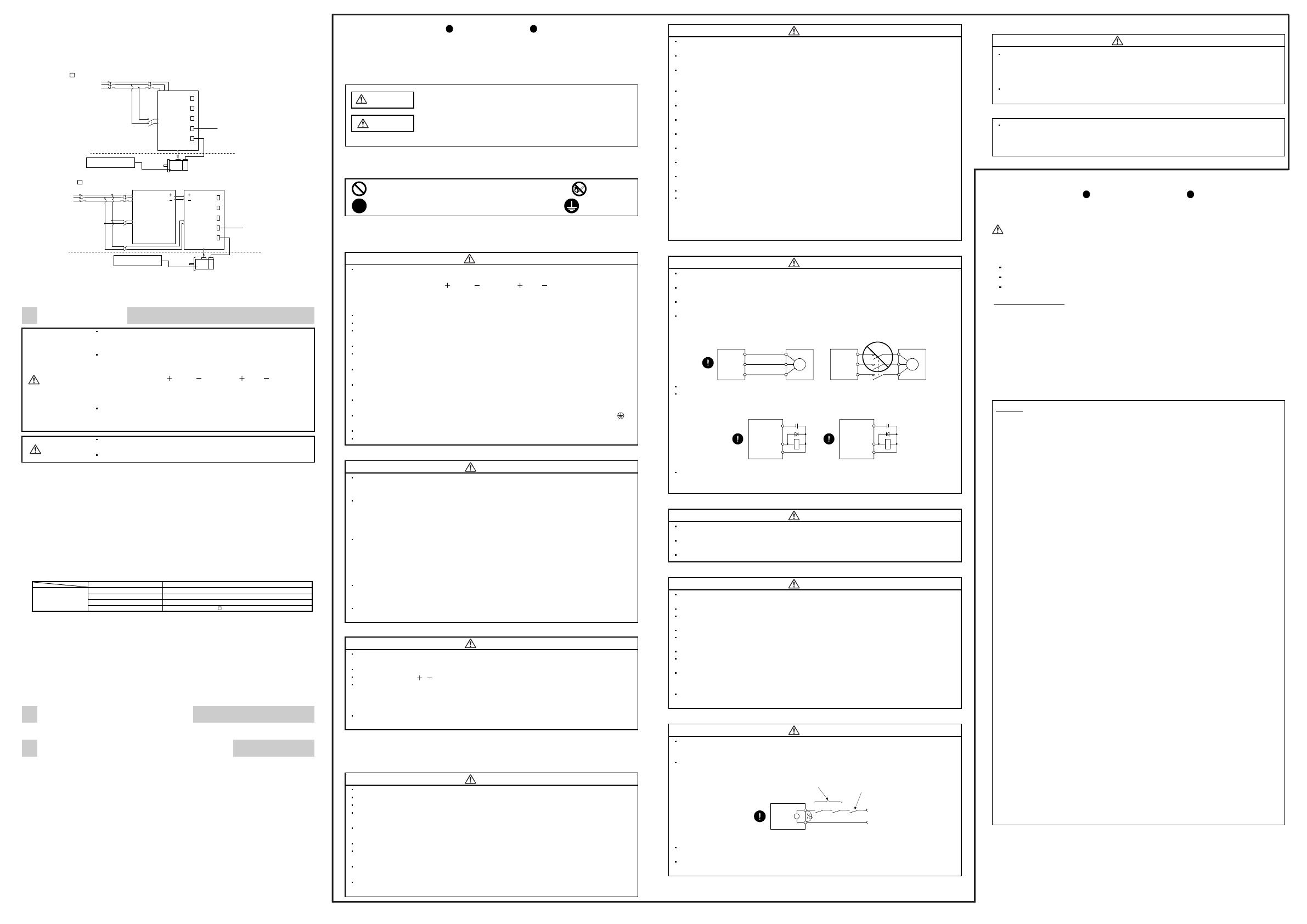
(12) Figure configuration
Representative configuration example to conform to the UL/cUL standard is shown below. The earth wiring is
excluded from the figure configuration.
(a) MR-J3-22K
(4) or less
MCCB
or fuse
L
1
/L
2
/L
3
L
11
CN5
CN3
CN1
CN2
CN6
U/V/W/PE
Servo amplifier
MCCB
or fuse
L
21
To protective equipment
(Thermal signal) (Note 2)
Power
s
uppl
y
Command device
Encoder cable
Cabinet side
Machine side
Servo motor
Encoder
(Note 1)
(b) MR-J3-DU30K
or more
MCCB
or fuse
L
CN5
CN3
CN1
CN2
CN6
U/V/W/PE
L
1
Drive unit
MCCB
or fuse
(Note 1)
MCCB
or fuse
(Note 1)
L
2
L
3
L
11
L
21
L
11
L
21
L
To protective equipment
(Thermal signal) (Note 2)
Powe
r
s
uppl
y
Command device
Encoder cable
Cabinet side
Machine side
Servo motor
Encoder
Converter unit
L
L
Note 1. When the wire sizes of L
1
and L
11
are the same, MCCB or fuse is not required.
2. Please use a thermal sensor, etc. for thermal protection of the servo motor.
The control circuit connectors described by rectangles are safely separated from the main circuits described by
circles.
5. INSPECTION
WARNING
If you need to get close to the moving parts of the machine for inspection
or others, ensure safety by confirming the power off, etc. Otherwise, it
may cause an accident.
Before starting maintenance and/or inspection, turn off the power and
wait 15 minutes or more (wait more than 20 minutes in the case of the
drive unit is 30kW or more) until the charge lamp goes off. Then, confirm
the voltage between P( ) and N( ) (between L and L in the case of
the drive unit is 30kW or more) is safe with a voltage tester and others to
prevent an electric shock. In addition, always confirm from the front of the
servo amplifier (converter unit), whether the charge lamp is off or not.
To avoid the risk of electric shock, only qualified personnel should
attempt inspections. For repair and parts replacement, contact your local
sales office.
CAUTION
Do not perform insulation resistance test on the servo amplifier (drive
unit) as damage may result.
Do not disassemble and/or repair the equipment on customer side.
(1) Inspection
It is recommended to make the following checks periodically.
(a) Check for loose terminal block screws. Retighten any loose screws.
(b) Check the cables and the like for scratches and cracks. Perform periodic inspection according to operating
conditions.
(c) Check that the connector is securely connected to the servo amplifier.
(d) Check that the wires are not coming out from the connector.
(e) Check for dust accumulation on the servo amplifier.
(f) Check for unusual noise generated from the servo amplifier.
(2) Life
The following parts must be changed periodically as listed below. If any part is found faulty, it must be changed
immediately even when it has not yet reached the end of its life, which depends on the operating method and
environmental conditions.
For use in the atmosphere having much oil mist, dust, etc., clean and inspect every three months.
For parts replacement, please contact your sales representative.
Part name Standard life
Converter unit and
Servo amplifier
(drive unit)
Smoothing capacitor 10 years
Relay Number of power-on and number of emergency stop times: 100,000 times
Cooling fan 10,000 to 30,000 hours (2 to 3 years)
Absolute position battery Refer to the MR-J3- Servo Amplifier Instruction Manual.
(a) Smoothing capacitor
Affected by ripple currents, etc. and deteriorates in characteristic. The life of the capacitor greatly depends on
ambient temperature and operating conditions. The capacitor will reach the end of its life in 10 years of continuous
operation in normal air-conditioned environment (Surrounding air temperature of 40°C (104°F) or less.).
(b) Relays
Their contacts will wear due to switching currents and contact faults occur. Relays reach the end of their life
when the cumulative number of power-on and emergency stop times is 100,000, which depends on the power
supply capacity
(c) Converter unit and servo amplifier (drive unit) cooling fan
The cooling fan bearings reach the end of their life in 10,000 to 30,000 hours. Normally, therefore, the fan
must be changed in a few years of continuous operation as a guideline.
It must also be changed if unusual noise or vibration is found during inspection.
6. ALARMS AND WARNINGS
For details on each type of alarms or warnings, refer to each servo amplifier technical instruction.
7. COMPLIANCE WITH STANDARDS
MR-J3 servo amplifiers comply with the following standards.
IEC/EN/KN 61800-3/GB 12668.3
Safety Instructions
Please read the instructions carefully before using the equipment.
Install, and peruse all this guide and attached documents before the drive and maintenance and the
check. After that, use these correctly. Use it after it is skilled of the knowledge of the equipment,
information on safety, and all of notes. In this guide, the safety instruction levels are classified into
"WARNING" and "CAUTION".
WARNING
Indicates that incorrect handling may cause hazardous conditions, resulting in
death or severe injury.
CAUTION
Indicates that incorrect handling may cause hazardous conditions, resulting in
medium or slight injury to personnel or may cause
physical damage.
Note that the CAUTION level may lead to a serious consequence according to conditions. Please follow
the instructions of both levels because they are important to personnel safety. What must not be done and
what must be done are indicated by the following diagrammatic symbols.
: Indicates what must not be done. For example, "No Fire" is indicated by .
: Indicates what must be done. For example, grounding is indicated by .
In this guide, instructions at a lower level than the above, instructions for other functions, and so on are
classified into "POINT". After reading this guide, always keep it accessible to the operator.
1. To prevent electric shock, note the following
WARNING
Before wiring or inspection, turn off the power and wait 15 minutes or more (wait more than 20
minutes in the case of the drive unit is 30kW or more) until the charge lamp goes off. Then,
confirm the voltage between P( ) and N( ) (between L and L in the case of the drive unit is
30kW or more) is safe with a voltage tester and others to prevent an electric shock. In addition,
always confirm from the front of the servo amplifier (converter unit), whether the charge lamp is
off or not.
Connect the converter unit and servo amplifier (drive unit) and servo motor to ground.
Any person who is involved in wiring and inspection should be fully competent to do the work.
Do not attempt to wire the converter unit and servo amplifier (drive unit) and servo motor until
they have been installed. Otherwise, it may cause an electric shock.
Operate the switches with dry hand to prevent an electric shock.
The cables should not be damaged, stressed loaded, or pinched. Otherwise, it may cause an
electric shock.
During power-on or operation, do not open the front cover. Otherwise, it may cause an electric
shock.
Do not operate the converter unit and servo amplifier (drive unit) with the front cover removed.
High-voltage terminals and charging area are exposed and it may cause an electric shock.
Except for wiring or periodic inspection, do not remove the front cover even if the power is off.
The converter unit and servo amplifier (drive unit) are charged and it may cause an electric shock.
To prevent an electric shock, always connect the protective earth (PE) terminal (marked ) of
the converter unit and servo amplifier (drive unit) to the protective earth (PE) of the cabinet.
When using a residual current device (RCD), select type B.
To avoid an electric shock, insulate the connections of the power supply terminals.
2. To prevent fire, note the following
CAUTION
Install the converter unit and servo amplifier (drive unit), servo motor and regenerative resistor on
incombustible material. Installing them directly or close to combustibles will lead to smoke or a
fire.
Always connect a magnetic contactor between the main circuit power supply and L
1
, L
2
, and L
3
of
the converter unit, servo amplifier, and configure the wiring to be able to shut down the power
supply on the side of the converter unit, servo amplifier’s power supply. If a magnetic contactor is
not connected, continuous flow of a large current may cause smoke or a fire when the converter
unit or servo amplifier (drive unit) malfunctions.
Always connect a molded-case circuit breaker, or a fuse to each servo amplifier between the
power supply and the main circuit power supply (L
1
, L
2
, and L
3
) of the servo amplifier (including
converter unit), in order to configure a circuit that shuts down the power supply on the side of the
servo amplifier’s power supply. If a molded-case circuit breaker or fuse is not connected,
continuous flow of a large current may cause smoke or a fire when the servo amplifier
malfunctions.
When a regenerative resistor is used, use an alarm signal to switch main power off. Otherwise, a
regenerative transistor malfunction or the like may overheat the regenerative resistor, causing
smoke or a fire.
Provide adequate protection to prevent screws and other conductive matter, oil and other
combustible matter from entering the converter unit, servo amplifier (drive unit) and servo motor.
3. To prevent injury, note the following
CAUTION
Only the voltage specified in the instruction manual should be applied to each terminal,
Otherwise, a burst, damage, etc. may occur.
Connect the terminals correctly to prevent a burst, damage, etc.
Ensure that polarity ( , ) is correct. Otherwise, a burst, damage, etc. may occur.
Take safety measures, e.g. provide covers, to prevent accidental contact of hands and parts
(cables, etc.) with the converter unit and servo amplifier (drive unit) heat sink, regenerative
resistor, servo motor, etc. since they may be hot while power is on or for some time after
power-off. Their temperatures may be high and you may get burnt or a parts may damaged.
During operation, never touch the rotating parts of the servo motor. Otherwise, it may cause
injury.
4. Additional instructions
The following instructions should also be fully noted. Incorrect handling may cause a fault, injury, electric
shock, fire, etc.
(1) Transportation and installation
CAUTION
Transport the products correctly according to their mass.
Stacking in excess of the specified number of products is not allowed.
Do not carry the servo motor by holding the cables, shaft, encoder or connector.
Do not hold the front cover to transport the converter unit and servo amplifier (drive unit). The
converter unit and servo amplifier (drive unit) may drop.
Install the converter unit and servo amplifier (drive unit) in a load-bearing place in accordance
with the instruction manual.
Do not get on or put heavy load on the equipment. Otherwise, it may cause injury.
The converter unit, servo amplifier (drive unit) and servo motor must be installed in the specified
direction.
Leave specified clearances between the converter unit, servo amplifier (drive unit) and control
enclosure walls or other equipment.
Do not install or operate the converter unit, servo amplifier (drive unit) and servo motor which has
been damaged or has any parts missing.
CAUTION
Do not block the intake and exhaust areas of the converter unit, servo amplifier (drive unit) and
servo motor with a cooling fan. Otherwise, it may cause a malfunction.
Do not drop or strike converter unit, servo amplifier (drive unit) and servo motor. Isolate from all
impact loads.
When storing or using the converter unit, servo amplifier (drive unit) and servo motor, comply with
the environmental conditions given in the Servo Amplifier Instruction Manual and Servo Motor
Instruction Manual.
Securely attach the servo motor to the machine. If attach insecurely, the servo motor may come
off during operation.
The servo motor with reduction gear must be installed in the specified direction to prevent oil
leakage.
Take safety measures, e.g. provide covers, to prevent accidental access to the rotating parts of
the servo motor during operation.
Never hit the servo motor or shaft, especially when coupling the servo motor to the machine.
Otherwise, the encoder may malfunction.
Do not subject the servo motor shaft to more than the permissible load. Otherwise, the shaft may
break.
When the equipment has been stored for an extended period of time, contact your local sales
office.
When treating the converter unit and servo amplifier (drive unit) be careful about the edged parts
such as the corners of the converter unit and servo amplifier (drive unit).
The converter unit and servo amplifier (drive unit) must be installed in the metal cabinet.
When fumigants that contain halogen materials such as fluorine, chlorine, bromine, and iodine
are used for disinfecting and protecting wooden packaging from insects, they cause malfunction
when entering our products. Please take necessary precautions to ensure that remaining
materials from fumigant do not enter our products, or treat packaging with methods other than
fumigation (heat method). Additionally, disinfect and protect wood from insects before packing
products.
(2) Wiring
CAUTION
Wire the equipment correctly and securely. Otherwise, the servo motor may operate
unexpectedly.
Do not install a power capacitor, surge killer or radio noise filter (FR-BIF (-H) option) between the
servo motor and servo amplifier (drive unit).
Connect the servo amplifier (drive unit) power output (U, V, and W) to the servo motor power
input (U, V, and W) directly. Not doing so may cause unexpected operation.
Connect the servo motor power terminal (U, V, W) to the servo motor power input terminal (U, V,
W) directly. Do not let a magnetic contactor, etc. intervene. Otherwise, it may cause a
malfunction.
U
Servo motor
M
V
W
U
V
W
Servo amplifier
(drive unit)
U
M
V
W
U
V
W
Servo motor
Servo amplifier
(drive unit)
Do not connect AC power directly to the servo motor. Otherwise, it may cause a malfunction.
The surge absorbing diode installed to the DC relay for control output should be fitted in the
specified direction. Otherwise, the emergency stop and other protective circuits may not operate.
DOCOM
Control output
signal
DICOM
24VDC
Servo amplifier
(drive unit)
RA
For sink output interface
DOCOM
Control output
signal
DICOM
24VDC
Servo amplifier
(drive unit)
RA
For source output interface
When the cable is not tightened enough to the terminal block (connector), the cable or terminal
block (connector) may generate heat because of the poor contact. Be sure to tighten the cable
with specified torque.
(3) Test run adjustment
CAUTION
Before operation, check the parameter settings. Improper settings may cause some machines to
perform unexpected operation.
Never make a drastic adjustment or change to the parameter values as doing so will make the
operation unstable.
Do not get close to moving parts during the servo-on status.
(4) Usage
CAUTION
Provide an external emergency stop circuit to ensure that operation can be stopped and power
switched off immediately.
Any person who is involved in disassembly and repair should be fully competent to do the work.
Before resetting an alarm, make sure that the run signal of the servo amplifier (drive unit) is off to
prevent an accident. A sudden restart is made if an alarm is reset with the run signal on.
Do not modify the equipment.
Use a noise filter, etc. to minimize the influence of electromagnetic interference, which may be
caused by electronic equipment used near the servo amplifier (drive unit).
Use the converter unit and servo amplifier (drive unit) with the specified servo motor.
The electromagnetic brake on the servo motor is designed to hold the motor shaft and should not
be used for ordinary braking.
For such reasons as service life and mechanical structure (e.g. where a ball screw and the servo
motor are coupled via a timing belt), the electromagnetic brake may not hold the motor shaft. To
ensure safety, install a stopper on the machine side.
Burning or breaking a converter unit and servo amplifier (drive unit) may cause a toxic gas. Do
not burn or break a converter unit and servo amplifier (drive unit).
(5) Corrective actions
CAUTION
When it is assumed that a hazardous condition may take place at the occur due to a power failure
or a product fault, use a servo motor with electromagnetic brake or an external brake mechanism
for the purpose of prevention.
Configure a circuit so that the electromagnetic brake activates with the external emergency stop
switch at the same time.
Servo motor
Electromagnetic brake
B
SON RA
24VDC
Contacts must be opened when the servo-on (SON)
signal, the malfunction (ALM) signal, or the electromagnetic
brake interlock (MBR) signal turns off.
Circuit must be opened
during emergency stop
switch.
When any alarm has occurred, eliminate its cause, ensure safety, and deactivate the alarm
before restarting operation.
Design the machine in order to avoid sudden restarting in case of after an instantaneous power
failure.
(6) Maintenance, inspection and parts replacement
CAUTION
With age, the electrolytic capacitor of the converter unit and servo amplifier (drive unit) will
deteriorate. To prevent a secondary accident due to a fault, it is recommended to replace the
electrolytic capacitor every 10 years when used in general environment. Please contact your local
sales office.
When using a converter unit and servo amplifier (drive unit) whose power has not been turned on
for a long time, contact your local sales office.
(7) General instruction
To illustrate details, the equipment in the diagrams of this guide and instruction manual may have
been drawn without covers and safety guards. When the equipment is operated, the covers and
safety guards must be installed as specified. Operation must be performed in accordance with
this guide and instruction manual.
DISPOSAL OF WASTE
Please dispose a converter unit, servo amplifier (drive unit), battery (primary battery) and other options
according to your local laws and regulations.
EEP-ROM life
The number of write times to the EEP-ROM, which stores parameter settings, etc., is limited to
100,000. If the total number of the following operations exceeds 100,000, the servo amplifier and/or
converter unit may fail when the EEP-ROM reaches the end of its useful life.
Writing to the EEP-ROM due to parameter setting changes
Home position setting in the absolute position detection system
Writing to the EEP-ROM due to device changes
Battery transportation
MR-J3BAT contains a lithium metal battery, ER6. MR-J3BAT is not subject to the dangerous goods
(Class 9) of the UN Recommendations.
To transport lithium metal batteries and lithium metal batteries contained in equipment by means of
transport subject to the UN Recommendations, take actions to comply with the following regulations: the
United Nations Recommendations on the Transport of Dangerous Goods, the Technical Instruction
(ICAO-TI) by the International Civil Aviation Organization (ICAO), and the International Maritime
Dangerous Goods Code (IMDG Code) by the International Maritime Organization (IMO).
To transport the batteries, check the latest standards or the laws of the destination country and take
actions.
For more information, contact your local sales office.
Warranty
1. Warranty period and coverage
We will repair any failure or defect hereinafter referred to as "failure" in our FA equipment hereinafter referred to as the
"Product" arisen during warranty period at no charge due to causes for which we are responsible through the distributor
from which you purchased the Product or our service provider. However, we will charge the actual cost of dispatching
our engineer for an on-site repair work on request by customer in Japan or overseas countries. We are not responsible
for any on-site readjustment and/or trial run that may be required after a defective unit are repaired or replaced.
[Term]
The term of warranty for Product is twelve (12) months after your purchase or delivery of the Product to a place
designated by you or eighteen (18) months from the date of manufacture whichever comes first (“Warranty Period”).
Warranty period for repaired Product cannot exceed beyond the original warranty period before any repair work.
[Limitations]
(1) You are requested to conduct an initial failure diagnosis by yourself, as a general rule. It can also be carried out by
us or our service company upon your request and the actual cost will be charged.
However, it will not be charged if we are responsible for the cause of the failure.
(2) This limited warranty applies only when the condition, method, environment, etc. of use are in compliance with the
terms and conditions and instructions that are set forth in the instruction manual and user manual for the Product
and the caution label affixed to the Product.
(3) Even during the term of warranty, the repair cost will be charged on you in the following cases;
(i)
(ii)
(iii)
(iv)
(v)
(vi)
(vii)
(
viii
)
: a failure caused by your improper storing or handling, carelessness or negligence, etc., and a failure caused
by your hardware or software problem
: a failure caused by any alteration, etc. to the Product made on your side without our approval
: a failure which may be regarded as avoidable, if your equipment in which the Product is incorporated is
equipped with a safety device required by applicable laws and has any function or structure considered to be
indispensable according to a common sense in the industry
: a failure which may be regarded as avoidable if consumable parts designated in the instruction manual, etc.
are duly maintained and replaced
: any replacement of consumable parts (battery, fan, smoothing capacitor, etc.)
: a failure caused by external factors such as inevitable accidents, including without limitation fire and
abnormal fluctuation of voltage, and acts of God, including without limitation earthquake, lightning and
natural disasters
: a failure generated by an unforeseeable cause with a scientific technology that was not available at the time
of the shipment of the Product from our company
: an
y
other failures which we are not res
p
onsible for or which
y
ou acknowled
g
e we are not res
p
onsible for
2. Term of warranty after the stop of production
(1) We may accept the repair at charge for another seven (7) years after the production of the product is discontinued.
The announcement of the stop of production for each model can be seen in our Sales and Service, etc.
(2) Please note that the Product (including its spare parts) cannot be ordered after its stop of production.
3. Service in overseas countries
Our regional FA Center in overseas countries will accept the repair work of the Product. However, the terms and
conditions of the repair work may differ depending on each FA Center. Please ask your local FA center for details.
4. Exclusion of responsibility for compensation against loss of opportunity, secondary loss, etc.
Whether under or after the term of warranty, we assume no responsibility for any damages arisen from causes for
which we are not responsible, any losses of opportunity and/or profit incurred by you due to a failure of the Product,
any damages, secondary damages or compensation for accidents arisen under a specific circumstance that are
foreseen or unforeseen by our company, any damages to products other than the Product, and also compensation for
any replacement work, readjustment, start-up test run of local machines and the Product and any other operations
conducted by you.
5. Change of Product specifications
Specifications listed in our catalogs, manuals or technical documents may be changed without notice.
6. Application and use of the Product
(1) For the use of our General-Purpose AC Servo, its applications should be those that may not result in a serious
damage even if any failure or malfunction occurs in General-Purpose AC Servo, and a backup or fail-safe function
should operate on an external system to General-Purpose AC Servo when any failure or malfunction occurs.
(2) Our General-Purpose AC Servo is designed and manufactured as a general purpose product for use at general
industries.
Therefore, applications substantially influential on the public interest for such as atomic power plants and other
power plants of electric power companies, and also which require a special quality assurance system, including
applications for railway companies and government or public offices are not recommended, and we assume no
responsibility for any failure caused by these applications when used.
In addition, applications which may be substantially influential to human lives or properties for such as airlines,
medical treatments, railway service, incineration and fuel systems, man-operated material handling equipment,
entertainment machines, safety machines, etc. are not recommended, and we assume no responsibility for any
failure caused by these applications when used.
We will review the acceptability of the abovementioned applications, if you agree not to require a specific quality
for a specific application. Please contact us for consultation.
  • Page 1 1
  • Page 2 2
  • Page 3 3
  • Page 4 4

Mitsubishi Electric AC Servos Operating instructions

Type
Operating instructions

Ask a question and I''ll find the answer in the document

Finding information in a document is now easier with AI

in other languages