13 MIDI FOOT CONTROLLER FCB1010 User Manual
The eects processor is controlled via MIDI, while the SWITCH function toggles
the amp. Thus, you’ll need no additional footswitch when you switch between
the channels; instead, your entire setup is centrally controlled from the FCB1010.
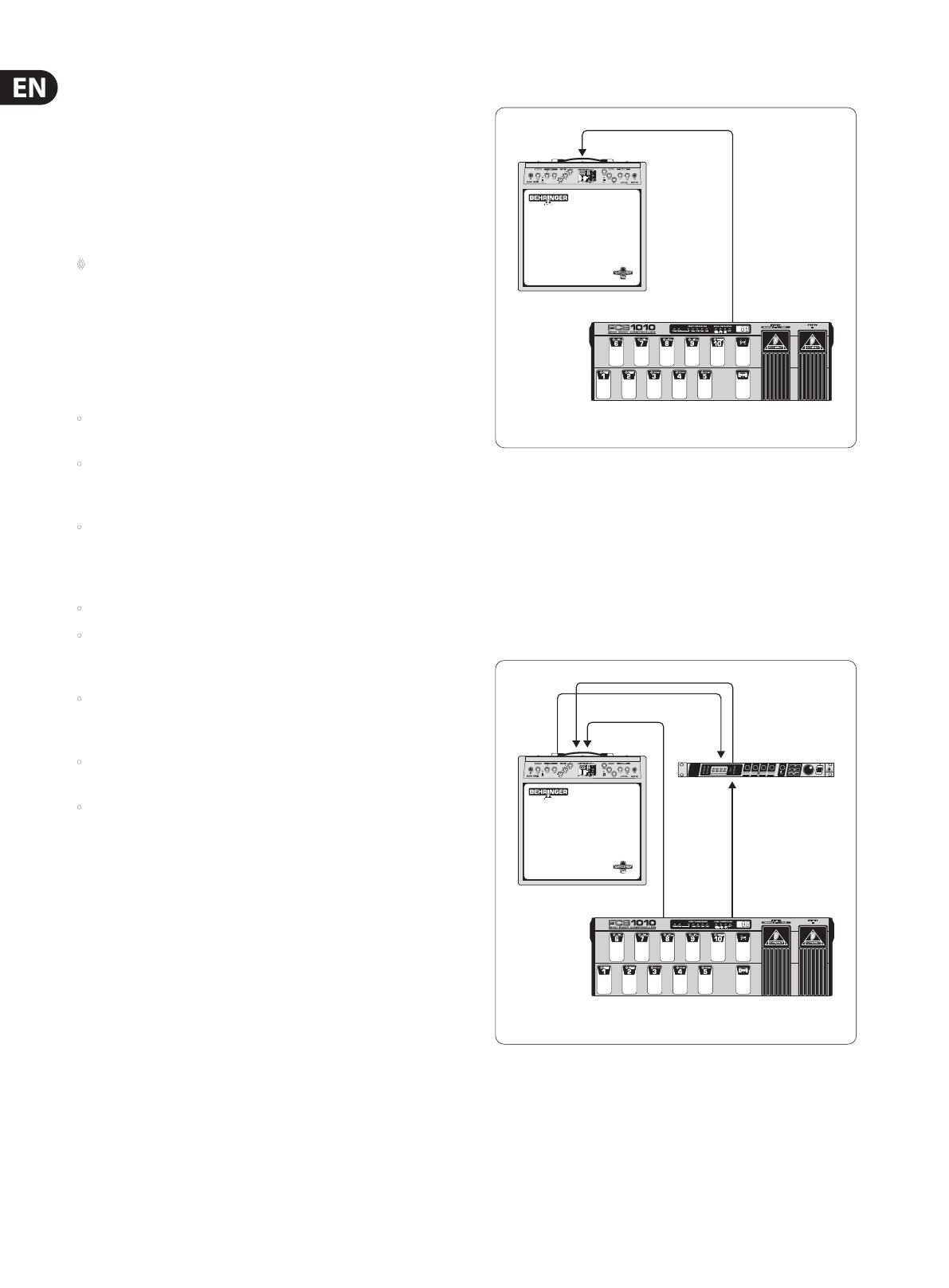
3.3 Connections (General)
Please use commercial-grade cables with phone plugs to connect the SWITCH
outputs of your FCB1010 to your amplier. Since these outputs are normalized,
you can send both switching pulses from one SWITCH output, by using a stereo
cable, which is useful in combination with ampliers that have a stereo phone
jack to select several functions (e.g. channel select and eect on/o). In this case,
please use only one of the two SWITCH outputs with one stereo cable connected.
◊ Find out whether or not your guitar amp supports a stereo connection
via SWITCH 1 or SWITCH 2. Simply try and experiment to identify the
switching configuration of your amp.
4. MIDI—A Standard, A Revolution
In the early 80’s several leading manufacturers of electronic musical instruments
developed a common standard, which was soon to revolutionize the entire MI
industry—both from a technical and musical point of view. The MIDI standard
(short for: Musical Instruments Digital Interface) was invented to allow musical
instruments of dierent makes to communicate with each other. What is
surprising in view of the rapidly developing MI industry is the fact that this
standard has basically not changed ever since, because it was designed with
future upgrades in mind. So, the MIDI interface’s range of applications could
be expanded over the years: from the simple connection of several keyboard
instruments to one master keyboard to connecting whole studios and live set-ups
within a single MIDI network—MIDI has become an innite source of ideas and
innovation. Numerous musicians recognized the versatility of this standard and
created new and exciting worlds of sounds by combining dierent instruments
to one homogeneous whole. It is important to know that the MIDI interface
transmits no audio signals but only control data (e.g. key, program change or
volume numbers)! MIDI is just an interface for the control and networking of
devices and instruments.
At the heart of this network you could use your FCB1010 to control all of your
ampliers, eects and peripheral devices. Live on stage and in the studio you
could control your entire equipment in real time. MIDI control data can be
stored and edited on a computer, so that you can also use your FCB1010 to enter
controller and program change information into your computer.
4.1 MIDI connections
The MIDI connectors on the rear of the unit are on internationally standardized
5-pin DIN jacks. To connect your FCB1010 to other MIDI devices you need
a dedicated MIDI cable. Usually, commercially available cables are used.
However,you can also use a two-conductor shielded cable (e.g. microphone
cable) and two (rugged) 180° DIN plugs to make your own MIDI cable: pin 2
(center) = shield, pins 4 and 5 (right and left of pin 2) = internal conductor,
pins1und 3 (the two outer pins) are not used. MIDI cables should not be longer
than 15meters.
MIDI IN: serves to receive recorded system-exclusive data or to merge any MIDI
signals with FCB1010-generated data.
◊ The FCB1010 has no dedicated MIDI THRU port. However, the data
received at the MIDI IN can be routed to the MIDI OUT provided that the
MERGE function is enabled (GLOBAL CONFIGURATION).
MIDI OUT: The MIDI OUT allows you to transmit data to any MIDI-compatible
device/instrument.
4.2 MIDI data format
Although the FCB1010 is very easy to operate, it does make sense to know a few
things about the format of MIDI data. Each MIDI command or message consists
of up to three bytes (1 byte = 8 bits). There’s a dierence between status bytes
and data bytes: status bytes dene the type of a specic MIDI message, i.e. the
actual instruction to be sent to a device, while data bytes contain the information
or parameters dened by the corresponding status byte. One status byte can be
followed by up to two data bytes.
There are various types of MIDI messages. Since the FCB1010 does not understand
or transmit all of them, we will only deal with those that are of importance to you
in this context.
4.2.1 NOTE ON and NOTE OFF messages
NOTE ON and NOTE OFF messages are essential MIDI messages for any keyboard
virtuoso, as they allow to control remote instruments from one master keyboard
or computer. The FCB1010, too, can send NOTE ON messages, however, in a
dierent context: many eects devices allow for “tapping” delay times, etc.,
bymeasuring the time interval between two NOTE ON messages. With the
FCB1010 you can “tap” delay times or song tempos by selecting a “NOTE”
PRESETtwice.
NOTE ON and NOTE OFF messages feature the following data format:
Status Byte Data Byte 1 Data Byte 2
Note O &8n (n = Kanalnr.) Notennr. Velocity
Note On &9n (n = Kanalnr.) Notennr. Velocity
Tab. 4.1: Data format of NOTE ON and NOTE OFF messages
The channel number range is 1 through 16, the data byte range is 0 through 127.
It should be noted though that NOTE OFF messages are not so common today
(forreasons of data reduction, cf. running status). Usually, NOTE ON messages
with zero velocity are transmitted instead. The FCB1010 follows this convention.
By the way: when you program the NOTE function on your FCB1010 you only need
to enter the note number, because notes are always transmitted with a velocity
of 64.
4.2.2 CONTROL CHANGE messages
CONTROL CHANGE messages are the most powerful MIDI messages, as they allow
you to select and automate plenty of parameters and functions. On your FCB1010
you can dene and transmit CONTROL CHANGE messages, e.g. to change specic
eects parameters in real time. The most important CONTROL CHANGE messages
are volume control (Controller 07), Balance (08), Panorama (09) and reverb
intensity (91).
4.2.3 PROGRAM CHANGE messages
PROGRAM CHANGE messages are used to change presets or sounds in connected
devices/instruments. The parameter range is 0 through 127.
The values 0 to 127 of the 128 presets are available. Equipment with more than
128 presets has these presets broken down into several banks for MIDI control.
With your FCB1010, it is possible to send MIDI bank and program change
commands by using just one keystroke. An external piece of equipment
(e.g.eects processor, sound module etc.) can be controlled via controllers 1 &
3 in connection with PRG 5 (PROG CHG). In doing so, controllers 1 & 2 are used
as 2-byte bank select controllers, whereby up to 128 (MSB) x 128 (LSB) banks
can be dialed in. Controller 1 needs to contain the number 00 and the MSB bank
value, while controller 2 needs to contain the number 32 and the LSB bank value.
Theprogram change command that activates the preset in the new bank is sent
with PRG 5.