Bosch WR8..P... Owner's manual
- Category
- Water heaters & boilers
- Type
- Owner's manual
This manual is also suitable for
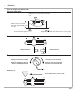
Bosch WR8..P... instantaneous water heater provides endless hot water and features a piezo ignition and double safety system for peace of mind. With adjustable output control, you can set your desired water temperature effortlessly. Its compact size and sleek design make it suitable for various locations, ensuring a continuous supply of hot water whenever you need it.
Bosch WR8..P... instantaneous water heater provides endless hot water and features a piezo ignition and double safety system for peace of mind. With adjustable output control, you can set your desired water temperature effortlessly. Its compact size and sleek design make it suitable for various locations, ensuring a continuous supply of hot water whenever you need it.


-
 1
1
-
 2
2
-
 3
3
-
 4
4
-
 5
5
-
 6
6
-
 7
7
-
 8
8
-
 9
9
-
 10
10
-
 11
11
-
 12
12


Bosch WR8..P... Owner's manual
- Category
- Water heaters & boilers
- Type
- Owner's manual
- This manual is also suitable for
Bosch WR8..P... instantaneous water heater provides endless hot water and features a piezo ignition and double safety system for peace of mind. With adjustable output control, you can set your desired water temperature effortlessly. Its compact size and sleek design make it suitable for various locations, ensuring a continuous supply of hot water whenever you need it.
Ask a question and I''ll find the answer in the document
Finding information in a document is now easier with AI
Related papers
Other documents
-
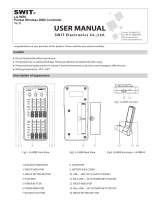 SWIT Electronics LA-WR8 User manual
-
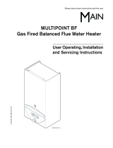 Main Multipoint BF User Operating, Installation And Servicing Instructions
-
DeWalt DXRH012E User manual
-
Admiral ZV4-1 Operating instructions
-
-
Bosch Appliances GWH 425 EF User manual
-
DeLonghi 634R User manual
-
-
-
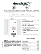 AquaStar 38B NG User manual


