190-00607-06 Rev D
10
GMX 200 Safety Monitor Codes
The GMX 200 is designed to detect anomalies and unexpected operational
and data events. When an anomaly or event occurs, the unit assumes the situ-
ation is unrecoverable and continued unit operation is ill-advisable. Regardless
of the code, neither the unit nor operator has enough information to identify the
source and resolve the problem. To avoid the possibility of displaying mislead-
ing data, the unit reboots itself to restore normal operations.
When an event occurs, the unit identifies the section of the software where
the problem was detected. A code is displayed on the error screen before the re-
boot and in the MSG function after the reboot. Codes are organized by subsys-
tem and functional block. See the table below for the list of codes. Error codes
include four digits. The first two identify the function or software section that
detected the error. The last two digits indicate a specific line or software instruc-
tion. The error code is an indication where the error was detected. However, in
most cases it is not where the error occurred.
If the error code condition clears and does not return after resetting the
unit, it can be assumed that the condition causing the code was temporary and
the unit will continue to function properly. If the condition causing the event
persists, the unit will detect the event and issue another reboot along with a
code, typically the same code. This will continue until the unit is turned off or
the condition causing the event is resolved.
Repeated occurrences of the same code indicate there may be a problem
with the installation, with a sensor providing data to the GMX 200, or within
the GMX 200. This situation should be analyzed in order to determine the
root cause of the problem. Should a code be displayed twice within a short
amount of time, please record the four-digit code if practical along with any
other symptoms or information, and report the event to your Garmin technical
support representative for further analysis. The GMX 200 also records log files
on the SD card. A copy of these files should also be provided to Garmin to help
investigate the problem.
Operational Response
Codes are not indicators that provide specific operational guidance (i.e., go
or no-go). There is no specific action to be taken by the flight crew based on the
displayed code. Codes are an indication that the unit may have received unex-
pected data, had a problem processing the received data, or other difficulty.
The following are recommended actions based on the current situation:
Pre-Flight and Post-Flight
If a code appears, the pilot should let the unit reboot. If the problem does
not reappear, the operation may proceed. If the code continues to appear mul-
tiple times, the pilot should have the problem investigated by a mechanic. Re-
peated problems must be reported to Garmin technical support representative
along with the code number and logfile(s).
During Flight
If a code appears, the pilot should let the unit reboot. If the problem does
not reappear, the flight may continue. If the code continues to appear multiple
times, the flight may continue at the pilot’s discretion. The pilot has the option
to turn the unit off. Repeated problems must be reported to Garmin technical
support representative along with the code number and logfile(s).
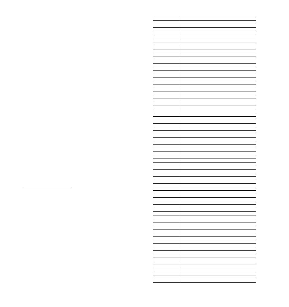
Code Subsystem
0xx Safety Monitor
1xx Startup
2xx GPS
3xx UAT
4xx Altitude
5xx General Drawing
6xx WX 500 (StrikeFinder)
7xx SL30
8xx Ryan TCAD
9xx Radar
10xx Radar
11xx Traffic (Skywatch, IHAS, GTX)
12xx WSI
13xx TAWS
14xx GDL 69
15xx Basemap
16xx Display Head
17xx Option Menu
18xx Annunciation Flags
19xx GAMA 429
45xx Weather (UAT/WSI)
46xx GPS
47xx Message
48xx GDL 69
49xx GDL 69 Weather
50xx Traffic
51xx Radar/TAWS
52xx IO
53xx IO
54xx IO
55xx Charts (Jepp)
56xx General Drawing
57xx GDL 69 Audio
58xx GDL 69 Audio
59xx Traffic
60xx Airports
61xx Airspace
62xx General Drawing
63xx General Function Drawing
64xx Charts
65xx Terrain
66xx Echo Tops (WSI)
67xx Weather (UAT/WSI)
68xx Flight Plan
69xx Option Menu
70xx Graphical METAR (UAT/WSI)
71xx Basemap
72xx IFR Map Function
73xx Intersections
74xx Lat/Lon Lines
75xx Basemap
76xx Custom Map Function
77xx Message Function
78xx Navaids
79xx NDBs
80xx Obstructions
81xx Baro Correction popup
82xx GDL 90 Code Edit
83xx Radar
84xx VFR Function
85xx Traffic
86xx Smart Key/Soft Key Menu
87xx Split Screen Function
88xx Lightning Function
89xx TAWS Function
90xx TFR (WSI)
91xx VOR Drawing
92xx Warning Areas (WSI)
93xx FIS Function (GDL 69)
94xx TAFS (WSI)
95xx Option Menu
96xx Configuration Module
98xx Startup tasks
99xx Traffic Subsystem


