Page is loading ...

66-ENGLISH
These Operating Instructions are printed on recycled paper.
Trademark acknowledgements
B The SD logo is a trademark.
B Windows is a trademark or registered trademark of Microsoft Corporation
in the United States of America and other countries.
B VGA and XGA are trademarks of International Business Machines
Corporation.
B Macintosh is a registered trademark of Apple Computer, Inc.
B S-VGA is a registered trademark of the Video Electronics Standards
Association.
All other trademarks are the property of the various trademark owners.
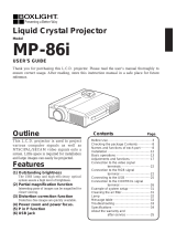
Dimensions
<Units: mm (inch)>
16(-5/8)
248(9-3/4)
58.6
(2-9/32)
8.6(-5/16)
115(4-1/2)
359(14-1/8)
*Not including lens and projecting parts
ENGLISH
R
Before operating this product, please read the instructions carefully and save this
manual for future use.
LCD Projector
Operating Instructions
Model No. PT-L735NTE
PT-L735E
AUTO SETUP
LASER
MENUVIDEO
Computer
PAGE
ENTER
R-CLICK
FREEZE
SHUTTER
Projector
FUNC1
STD
RGB
POWER
TQBJ 0126-1
Commercial Use

2-ENGLISH
IMPORTANT SAFETY NOTICE
WARNING:
To prevent damage which may result in fire or shock
hazard, do not expose this appliance to rain or moisture.
Machine Noise Information Ordinance 3. GSGV, January 18, 1991: The
sound pressure level at the operator position is equal or less than 70 dB
(A) according to ISO 7779.
WARNING:
1) Remove the plug from the wall outlet when this unit is not in use for a
prolonged period of time.
2) To prevent electric shock, do not remove cover. No user serviceable
parts inside. Refer servicing to qualified service personnel.
3) Do not remove the earthing pin on the power plug. This apparatus is
equipped with a three prong earthing-type power plug. This plug will only
fit an earthing-type power outlet. This is a safety feature. If you are
unable to insert the plug into the outlet, contact an electrician. Do not
defeat the purpose of the earthing plug.
Caution: To assure continued compliance, use only shielded interface
cables when connecting to computers or peripheral devices.
Any unauthorized changes or modifications to this equipment will
void the user's authority to operate.
Dear Panasonic Customer:
This instruction booklet provides all the necessary operating information that
you might require. We hope it will help you to get the most performance out
of your new product, and that you will be pleased with your Panasonic LCD
projector.
The serial number of your product may be found on its bottom. You should
note it in the space provided below and retain this booklet in case service is
required.
Model number: PT-L735NTE / PT-L735E
Serial number:
WARNING: THIS APPARATUS MUST BE EARTHED.
ENGLISH-3
Preparation
IMPORTANT: THE MOULDED PLUG (U.K. only)
FOR YOUR SAFETY, PLEASE READ THE FOLLOWING TEXT
CAREFULLY.
This appliance is supplied with a moulded three pin mains plug for your
safety and convenience. A 13 amp fuse is fitted in this plug. Should the fuse
need to be replaced, please ensure that the replacement fuse has a rating of
13 amps and that it is approved by ASTA or BSI to BS1362.
Check for the ASTA mark or the BSI mark on the body of the fuse.
If the plug contains a removable fuse cover, you must ensure that it is refitted
when the fuse is replaced. If you lose the fuse cover, the plug must not be
used until a replacement cover is obtained. A replacement fuse cover can be
purchased from an Authorised Service Centre.
If the fitted moulded plug is unsuitable for the socket outlet in your
home, then the fuse should be removed and the plug cut off and
disposed of safely. There is a danger of severe electrical shock if the
cut off plug is inserted into any 13 amp socket.
If a new plug is to be fitted, please observe the wiring code as shown below.
If in any doubt, please consult a qualified electrician.
WARNING: — THIS APPLIANCE MUST BE EARTHED.
IMPORTANT: — The wires in this mains lead are coloured in accordance
with the following code: —
Green-and-Yellow: Earth
Blue: Neutral
Brown: Live
As the colours of the wire in the mains lead of this appliance may not
correspond with the coloured markings identifying the terminals in your plug,
proceed as follows.
The wire which is coloured GREEN-AND-YELLOW must be connected
to the terminal in the plug which is marked with the letter E or by the
Earth symbol or coloured GREEN or GREEN-AND-YELLOW.
The wire which is coloured BLUE must be connected to the terminal in
the plug which is marked with the letter N or coloured BLACK.
The wire which is coloured BROWN must be connected to the terminal
in the plug which is marked with the letter L or coloured RED.
How to replace the fuse.
Open the fuse
compartment with a screwdriver and replace the
fuse.
ASA
13A250V
BS1363/A
HE-8
N
ASA
L
FUSE

ENGLISH-5
Preparation
Precautions with regard to safety
WARNING
If a problem occurs (such as no image or no sound) or if you notice
smoke or a strange smell coming from the projector, turn off the power
and disconnect the mains lead from the mains socket.
B Do not continue to use the projector in such cases, otherwise fire or
electric shocks could result.
B Check that no more smoke is coming out, and then contact an Authorised
Service Centre for repairs.
B Do not attempt to repair the projector yourself, as this can be dangerous.
Do not install this projector in a place which is not strong enough to
take the full weight of the projector.
B If the installation location is not strong enough, it may fall down or tip over,
and severe injury or damage could result.
Installation work (such as ceiling suspension) should only be carried
out by a qualified technician.
B If installation is not carried out correctly, there is the danger that injury or
electric shocks may occur.
If foreign objects or water get inside the projector, or if the projector is
dropped or the cabinet is broken, turn off the power and disconnect the
mains lead from the mains socket.
B Continued use of the projector in this condition may result in fire or electric
shocks.
B Contact an Authorised Service Centre for repairs.
Do not overload the mains socket.
B If the power supply is overloaded (for example, by using too many
adapters), overheating may occur and fire may result.
Do not remove the cover or modify it in any way.
B High voltages which can cause fire or electric shocks are present inside
the projector.
B For any inspection, adjustment and repair work, please contact an
Authorised Service Centre.
Clean the mains lead plug regularly to prevent it from becoming
covered in dust.
B If dust builds up on the mains lead plug, the resulting humidity can
damage the insulation, which could result in fire. Pull the mains lead out
from the mains socket and wipe it with a dry cloth.
B If not using the projector for an extended period of time, pull the mains
lead plug out from the mains socket.
4-ENGLISH
Contents
Preparation
IMPORTANT SAFETY NOTICE ...2
Precautions with regard to
safety .........................................5
Accessories .................................9
Before use ..................................10
Location and function of each
part...........................................12
Inserting the wireless card .......17
Getting started
Setting-up...................................18
Projection methods, Projector
position, Projection distances
Connections...............................20
Example of connecting to video
equipments, Example of connecting
to computer
Preparation for the remote
control unit..............................22
Basic Operation
Turning on the power................23
Turning off the power................25
Useful functions
Correcting keystone distortion
and automatic positioning.....27
Turning off the picture and sound
momentarily ............................28
Pausing a picture.......................28
Enlarging the picture.................29
Adjusting the volume ................29
Useful functions of the remote
control unit..............................30
Laser beam pointer, Wireless mouse
Adjustments and settings
On-screen menus ......................32
Menu screens, Menu operation
guide, Returning a setting to the
factory default
Adjusting the picture.................37
PICTURE MODE, CONTRAST,
BRIGHT, COLOR, TINT,
SHARPNESS, Colour Hue Setting,
Noise Reduction (NR), WHITE
BALANCE R/G/B, TV-SYSTEM,
Projecting sRGB-compatible pictures
Adjusting the position...............40
POSITION, DOT CLOCK, CLOCK
PHASE, KEYSTONE,
OSD POSION
,
ASPECT, RESIZING,
AUTO SETUP, FRAME LOCK
Audio adjustment ......................44
VOLUME, MUTE, AUDIO MODE
Changing the display language
...44
Option settings ..........................45
OSD, AUTO SEARCH,
AUTO SIGNAL, AUTO KEYSTN,
RGB2 SELECT, RGB/YPBP
R,
VGA60/525P, BLACKBOARD,
BACK COLOR, FRONT/REAR,
DESK/CEILING, FAN CONTROL,
LAMP POWER, LAMP RUN TIME,
FUNC 1, CONTROL KEY,
AUTO POWER OFF
Network setup............................48
SD card setup ............................48
Setting up the SECURITY
function ...................................49
PASSWORD SETTING, CHANGE
PASSWORD, TEXT DISPLAY,
CHANGE TEXT, LOGO DISPLAY,
CLEAR, CAPTURE
Care and maintenance
When the TEMP indicator and the
LAMP indicator are illuminated
...52
Cleaning and replacing
the air filter ..............................54
Replacing the lamp unit ............55
Before calling for service..........58
Cleaning and maintenance .......59
Others
Specifications ............................60
Appendix ....................................62
List of compatible signals,
Connector pin wiring, Projection
dimensions calculation methods,
Using the SERIAL connector
Dimensions ................................66
Trademark acknowledgements
...66

ENGLISH-7
Preparation
6-ENGLISH
Do not look into the lens while the projector is being used.
B Strong light is emitted from the projector’s lens. If you look directly into this
light, it can hurt and damage your eyes.
B Be especially careful not to let young children look into the lens. In
addition, turn off the power when you are away from the projector.
Keep the remote control unit out of the reach of children, and do not
look into the laser beam or point it towards other people.
B If the laser beam which is emitted by the remote control unit transmitter is
pointed directly into the eyes, it may cause visual ability to be impaired.
Do not bring your hands or other objects close to the air outlet port.
B Heated air comes out of the air outlet port. Do not bring your hands or
face, or objects which cannot withstand heat close to this port, otherwise
burns or damage could result.
When replacing the lamp, allow it to cool for at least one hour before
handling it.
B The lamp cover gets very hot, and contact with it can cause burns.
Before replacing the lamp, be sure to unplug the mains lead from the
power outlet.
B Electric shocks or explosions can result if this is not done.
Caution
Do not cover the air inlet or the air outlet.
B Doing so may cause the projector to overheat, which can cause fire or
damage to the projector.
B Do not place the projector in narrow, badly ventilated places such as
closets or bookshelves.
Do not set up the projector in humid or dusty places or in places where
the projector may come into contact with smoke or steam.
B Using the projector under such conditions may result in fire or electric
shocks.
When disconnecting the mains lead, hold the plug, not the cord.
B If the mains lead itself is pulled, the cord will become damaged, and fire,
short-circuits or serious electric shocks may result.
Always disconnect all cables before moving the projector.
B Moving the projector with cables still attached can damage the cables,
which could cause fire or electric shocks to occur.
Do not place any heavy objects on top of the projector.
B Failure to observe this may cause the projector to become unbalanced
and fall, which could result in damage or injury.
Do not short-circuit, heat or disassemble the batteries or place them
into water or fire.
B Failure to observe this may cause the batteries to overheat, leak, explode
or catch fire, and burns or other injury may result.
Do not do anything that might damage the mains lead or the mains lead
plug.
B Do not damage the mains lead, make any modifications to it, place it near
any hot objects, bend it excessively, twist it, pull it, place heavy objects on
top of it or wrap it into a bundle.
B If the mains lead is used while damaged, electric shocks, short-circuits or
fire may result.
B Ask an Authorised Service Centre to carry out any repairs to the mains
lead that might be necessary.
Do not handle the mains lead plug with wet hands.
B Failure to observe this may result in electric shocks.
Insert the mains lead plug securely into the mains socket.
B If the plug is not inserted correctly, electric shocks or overheating could
result.
B Do not use plugs which are damaged or mains sockets which are coming
loose from the wall.
Do not place the projector on top of surfaces which are unstable.
B If the projector is placed on top of a surface which is sloped or unstable, it
may fall down or tip over, and injury or damage could result.
Do not place the projector into water or let it become wet.
B Failure to observe this may result in fire or electric shocks.
Do not place liquid containers on top of the projector.
B If water spills onto the projector or gets inside it, fire or electric shocks
could result.
B If any water gets inside the projector, contact an Authorised Service
Centre.
Do not insert any foreign objects into the projector.
B Do not insert any metal objects or flammable objects into the projector or
drop them onto the projector, as doing so can result in fire or electric shocks.
Keep the SD memory card (PT-L735NTE only) and batteries out of the
reach of infants.
B If the memory card or batteries are swallowed, death by suffocation may
result. If you believe that the memory card or batteries may have been
swallowed, seek medical advice immediately.
Do not allow the + and - terminals of the batteries to come into contact
with metallic objects such as necklaces or hairpins.
B Failure to observe this may cause the batteries to leak, overheat, explode
or catch fire.
B Store the batteries in a plastic bag and keep them away from metallic objects.
During a thunderstorm, do not touch the projector or the cable.
B Electric shocks can result.
Do not use the projector in a bath or shower.
B Fire or electric shocks can result.

ENGLISH-9
Preparation
8-ENGLISH
When inserting the batteries, make sure the polarities (+ and -) are
correct.
B If the batteries are inserted incorrectly, they may explode or leak, and fire,
injury or contamination of the battery compartment and surrounding area
may result.
Use only the specified batteries.
B If incorrect batteries are used, they may explode or leak, and fire, injury or
contamination of the battery compartment and surrounding area may
result.
Do not mix old and new batteries.
B If the batteries are inserted incorrectly, they may explode or leak, and fire,
injury or contamination of the battery compartment and surrounding area
may result.
Do not put your weight on this projector.
B You could fall or the projector could break, and injury may result.
B Be especially careful not to let young children climb onto the projector.
Disconnect the mains lead plug from the mains socket as a safety
precaution before carrying out any cleaning.
B Electric shocks can result if this is not done.
Do not install the accessory wireless card to any device other than the
card slot of the projector. (PT-L735NTE only)
B If this is not observed, damage to the device may result.
Ask an Authorised Service Centre to clean inside the projector at least
once a year.
B If dust is left to build up inside the projector without being cleaned out, it
can result in fire or problems with operation.
B It is a good idea to clean the inside of the projector before the season for
humid weather arrives. Ask your nearest Authorised Service Centre to
clean the projector when required. Please discuss with the Authorised
Service Centre regarding cleaning costs.
We are constantly making efforts to preserve and maintain a clean
environment. Please take non repairable units back to your dealer or a
recycling company.
Accessories
Check that all of the accessories shown below have been included with your
projector.
Remote control unit
(N2QAEA000015 x1)
Power cord for
Continental Europe
(K2CM3FZ00001 x 1)
Power cord for U.K.
(K2CT3FZ00001 x 1)
AAA batteries for
remote control unit (x2)
RGB signal cable
[3.0 m (9´10˝),
K1HB15FA0001 x1]
Video/Audio cable
[3.0 m (9´10˝),
K2KA2FA00001 x 1]
USB cable
(K1HB04FD0002 x 1)
AUTO SETUP
LASER
MENUVIDEO
Computer
PAGE
ENTER
R-CLICK
FREEZE
SHUTTER
Projector
FUNC1
STD
RGB
POWER
Carrying bag
(TPEP010 x1)
CD-ROM
(TQBH9004 x1)
Wireless Card
(N5HBD0000024 x1)
SD memory card
(8 MB,
RP-SD008BEZ0 x1)
Protective case for SD
memory card
(RP-SDCC0 x1)
Hexagon wrench
(TKLA0701
x1)
PT-L735NTE only

ENGLISH-11
Preparation
10-ENGLISH
Notes on use
In order to get the best picture quality
Draw curtains or blinds over any windows and turn off any
fluorescent lights near the screen to prevent outside light or
light from indoor lamps from shining onto the screen.
Do not touch the surfaces of the lens with your bare
hands.
If the surface of the lens becomes dirty from fingerprints or
anything else, this will be magnified and projected onto the
screen. Moreover, when not using the projector, retract the
lens and then cover it with the accessory lens cover.
About the screen
Do not apply any volatile substances which may cause
discolouration to the screen, and do not let it become dirty or
damaged.
About the wireless card and SD memory card
(PT-L735NTE only)
Static electricity from the human body can damage the
wireless card or SD memory card. To prevent this, you should
touch a nearby metallic object such as an aluminium sash or a
door knob to dissipate the static charge from your body.
About the wireless card slot and SD memory card slot
(PT-L735NTE only)
Make sure that there are no foreign objects inside the slot
when inserting the wireless card or SD memory card. Failure
to observe it may damage the card and the slot.
About the lamp
The lamp may need to be replaced earlier due to variables
such as individual lamp characteristics, usage conditions and
the installation environment, especially when the projector is
subjected to continuous use for more than 10 hours or the
power is frequently turned on and off.
Before use
Cautions when moving the projector
Be sure to attach the lens cover before moving the
projector.
The projection lens is extremely susceptible to vibration and
shocks. When moving the projector, use the accessory
carrying bag. When placing the projector inside the carrying
bag, position it so that the lens is facing upward.
Cautions regarding setting-up
Avoid setting up in places which are subject to vibration
or shocks.
The internal parts can be damaged, which may cause
malfunctions or accidents.
Do not set up the projector near high-voltage power lines
or near motors.
The projector may be subject to electromagnetic interference.
If installing the projector to the ceiling, ask a qualified
technician to carry out all installation work.
You will need to purchase the separate installation kit (Model
No.ET-PK735). Furthermore, all installation work should only
be carried out by a qualified technician.
If using this projector at high elevations (above 1400 m),
set the FAN CONTROL to “HIGH”. (Refer to page 46.)
Failure to observe this may result in malfunctions.

Projector <Top, right and front>
ENGLISH-13
Preparation
12-ENGLISH
# Security lock
This can be used to connect a
commercially-available theft-
prevention cable (manufactured
by Kensington). This security lock
is compatible with the Microsaver
Security System from
Kensington. Contact details for
this company are given below.
Kensington Technology Group
ACCO Brands Inc.
2855 Campus Drive
San Mateo, CA 94403 USA
Tel (650)572-2700
Fax (650)572-9675
http://www.kensington.com/
http://www.gravis.com/
$ Remote control signal receptor
(page 22)
% Air outlet port
Do not cover this port.
& Carrying handle
' Speaker (R)
( Lamp unit holder
(page 56)
WARNING
Do not bring your hands or other
objects close to the air outlet port.
B Heated air comes out of the air
outlet port. Do not bring your
hands or face, or objects which
cannot withstand heat close to
this port, otherwise burns or
damage could result.
Projector <Back and bottom>
Location and function of each part
# Focus ring
(page 24)
$ Zoom ring
(page 24)
% Projector control panel
(page 14)
& Connector panel
(page 16)
' MAIN POWER switch
(pages 23 and 25)
( Power input socket (AC IN)
(page 23)
The accessory mains lead is
connected here.
Do not use any mains lead other
than the accessory mains lead.
) Speaker (L)
* Air inlet ports
Do not cover these ports.
+ Air filter
(page 54)
, Front adjustable legs(L/R)
(page 24)
- Leg adjuster buttons(L/R)
(page 24)
These buttons are used to unlock the
front adjustable legs. Press to adjust
the angle of tilt of the projector.
. Remote control signal receptor
(page 22)
/ Lens cover
0 Projection lens
1 Wireless card slot
(PT-L735NTE only)
Insert the wireless card into here.
(Refer to page 17.)
2 Eject switch
(PT-L735NTE only)
Use to remove the wireless card
from the card slot.
3 Access lamp
(PT-L735NTE only)
Flashes while the projector is being
accessed for reading or writing the
data in the SD memory card.
4 SD memory card slot
(PT-L735NTE only)
Insert the SD memory card into
here.
NOTE:
B During projection of an image,
the cooling fan will operate,
emitting a small noise as it
operates. Turning the lamp on
or off will cause this noise to
increase a little.
B
By using the OPTION menu to set
LAMP POWER to
“
LOW
”
, the
operating sound of the fan can be
reduced. (Refer to page 46.)
/
,
-
*
#
$
0
. -,
(
1
3
4
2
% & '
+ * )
PT-L735NTE only
&%$
#
'
(
NOTE:
B Information given above may
be changed in future.

ENGLISH-15
Preparation
# RGB INPUT indicator
(page 26)
This indicator shows whether a
signal is being input to the RGB
input connectors (RGB 1 IN/RGB
2 IN). When an input signal is
detected, the indicator illuminates.
$ LAMP indicator
(page 53)
This indicator illuminates when it
is time to replace the lamp unit. It
flashes if a circuit abnormality is
detected.
% TEMP indicator
(page 52)
This indicator illuminates if an
abnormally high or low
temperature is detected inside
the projector or around it. If the
temperature reaches a certain
level, the power supply will be
turned off automatically and the
indicator will flash.
& Power indicator
(page 23, 25 and 26)
This indicator illuminates red when
the MAIN POWER switch is turned
on (standby mode), and illuminates
green when the power is turned on
and a picture starts to be projected.
When the WEB STANDBY is set to
“ON”, the cooling fan operates and
the power indicator on the projector
flashes slowly in red.
' POWER button
(pages 23 and 25)
( Input select (VIDEO, RGB)
buttons
(page 24)
These buttons are used to select
the input signals. When AUTO
SEARCH in the OPTION menu is
set to “ON”, the input signal will be
detected and selected automatically
by pressing this button for a few
seconds. (Refer to page 45.)
) AUTO SETUP button
(pages 24 and 27)
If this button is pressed while a
picture is being projected, the
projection settings will be adjusted
automatically in accordance with
14-ENGLISH
Projector control panel
Remote control unit
.
/
0
#
$
%
&
' (
* + , -
)
'
(
)
2
3
+
1
,
-
4
*
8
5
6
7
9
AUTO SETUP
LASER
MENUVIDEO
Computer
PAGE
ENTER
R-CLICK
FREEZE
SHUTTER
Projector
FUNC1
STD
RGB
POWER
the signal being input. In addition,
the angle of tilt of the projector will
be automatically detected and
adjusted in order to correct any
keystone distortion.
* SHUTTER button
(page 28)
This button is used to
momentarily turn off the picture
and sound.
+ MENU button
(pages 32 and 35)
This button is used to display the
menu screens. When a menu
screen is being displayed, this
button can be used to return to a
previous screen or to clear the
screen.
, Arrow (
FFGGII
and
HH
) buttons
(page 35)
These buttons are used to select and
adjust items in the menu screens.
*When in computer operating
mode, these buttons on the
remote control unit function
differently. (page 31)
- ENTER button
(page 35)
This button is used to accept and
to activate items selected in the
on-screen menus.
*When in computer operating
mode, this button on the remote
control unit functions differently.
(page 31)
. Laser emitter
(page 30)
/ Infrared emitter
(page 22)
0 Click button
(page 31)
This button can be used when the
operating mode select switch is
moved to the left (Computer).
1 PAGE button
(page 31)
This button can be used when the
operating mode select switch is
moved to the left (Computer).
2 Operation indicator
(page 30)
This indicator illuminates while a
laser beam is being emitted
(while the LASER button is being
pressed). It flashes when any
other buttons are being pressed.
3 LASER button
(page 30)
A beam of laser light is emitted while
this button is being pressed. This
laser beam can be used as a pointer
to point to something on the screen.
4 FREEZE button
(page 28)
This button is used to
momentarily freeze projection so
that a still picture is displayed.
5 D.ZOOM +/- buttons
(page 29)
These buttons are used to
enlarge the projected image.
6 VOLUME +/- buttons
(page 29)
These buttons are used to adjust the
volume of the sound that is output
from the projector’s built-in speaker
and AUDIO OUT jack. Refer to page
44 for details on how to adjust the
volume using the buttons on the
projector control panel.
7 FUNC1 (function) button
(pages 41,44 and 46)
This button can be used for 1)
switching on and off the sound
volume and 2) entering into the
keystone distortion correction mode.
Use the FUNC1 item in the OPTION
menu to select which you wish to use.
8 STD (standard) button
(page 36)
This button is used to reset the
projector adjustment values to the
factory default settings.
9 Operating mode (Computer,
Projector) select switch
(page 31)
Move this switch to the left side to
use the remote control unit to
operate a computer, and move it to
the right side to operate the projector.

ENGLISH-17
Preparation
16-ENGLISH
(PT-L735NTE only)
Wireless card SD memory card
$
%
#
LOCK
'
&
Front Back
# Connector
This connector is for connecting
the wireless card to the
projector’s card slot. Be careful
not to touch the connector.
$ Wireless card power indicator
Illuminates when the wireless
card is operating.
% Wireless card access indicator
Flashes while the projector is
being accessed with personal
computers by means of a
wireless network.
& Metal terminals
These terminals are for
connecting the SD memory card
to the projector’s card slot. Do not
touch the metal terminals with
hands or metal objects, attach
stickers to them, or allow them to
become contaminated in any way.
' Write-protect switch
If the write-protect switch on the
SD memory card is moved to the
LOCK position, it will not be
possible to use any file editing
functions such as deleting or
moving image files.
Inserting the wireless card (PT-L735NTE only)
Insert the wireless card before using the PT-L735NTE.
Hexagon wrench
(accessory)
%
#
$
Eject switch
Card lock fixing
screw
#
Insert the wireless card until it locks.
$ Set the accessory card lock.
% Fasten the card lock with the card
lock fixing screw using the
hexagon wrench.
The card lock is already installed at
the factory default setting. When
you insert the wireless card, first
remove the card lock fixing screw
using the hexagon wrench to
release the card lock.
B When removing the wireless card, remove the card lock, and then press
the eject switch.
Card lock
Connector panel
# USB port
(page 31)
The remote control unit can be
used as
a personal computer
mouse by connecting the
projector to
a personal computer
with the supplied USB cable.
(4-pin square connector)
$ SERIAL connector
(pages 20, 21 and 64)
This connector is used to connect
a personal computer to the
projector in order to externally
control the projector. (RS-232C
compatible)
% RGB1 IN connector
(pages 20 and 21)
This connector is used to input
RGB signals and YP
BPR signals.
& RGB2 IN/RGB1 OUT connector
(pages 20, 21 and 45)
This connector is used to input or
output RGB signals and YP
BPR
signals. Use the RGB2 SELECT
item in the OPTION menu to
select whether you want input or
output with this connector.
' AUDIO OUT jack
(pages 20 and 21)
This jack is used to output the
audio signals which are input to
the projector. If audio equipment
is connected to this jack, no
sound will be output from the
built-in speaker.
( RGB AUDIO IN jack
(pages 20 and 21)
Only one system is provided, so
connect the appropriate
connector when using RGB1 or
RGB2.
) S-VIDEO IN connector
(pages 20 and 43)
This connector is used to input
signals from a S-VIDEO-compatible
equipment such as a video deck.
* VIDEO IN jack
(page 20)
This jack is used to input video
signals from a video equipment
such as a video deck.
+ AUDIO IN L-R (for VIDEO/S-
VIDEO) jacks
(page 20)
Only one system is provided, so
connect the appropriate
connector when using VIDEO or
S-VIDEO.
# $ % &
*
( )
'
+

ENGLISH-19
Getting started
18-ENGLISH
Projector position
H1
L
L
SH
SW
16
(-5/8)
L: Projection distance
SH: Image height
SW:Image width
H1: Distance from centre
of lens to bottom edge
of projected image
Top edge of screen
Screen
Bottom edge of screen
Screen
Projection distances
NOTE:
B The dimensions in the table above are approximate.
B If you use the projection distance for the 16:9 screen,
the 4:3 projection image overflows the screen at the top
and bottom.
B For details about projected image distances, refer to
page 63.
<Units: mm (inch)>
Setting-up
Projection methods
In way of installing projector, any one of the following four projection methods
are used. Select whichever projection method matches the setting-up
method. (The projection method can be set from the OPTION menu. Refer to
page 46 for details.)
BFront-desk projection BFront-ceiling projection
BRear-desk projection
(Using a translucent screen)
BRear-ceiling projection
(Using a translucent screen)
Menu items Setting
FRONT
DESK
FRONT/REAR
DESK/CEILING
Menu items Setting
FRONT
CEILING
FRONT/REAR
DESK/CEILING
Menu items Setting
REAR
DESK
FRONT/REAR
DESK/CEILING
Menu items Setting
REAR
CEILING
FRONT/REAR
DESK/CEILING
NOTE:
B You will need to purchase the separate ceiling bracket (ET-PK735)
when using the ceiling installation method.
B If you set up the projector vertically, it may cause
to damage the projector.
B It is recommended that you set up the projector
in a place that is tilted at less than
±30°. Setting
up the projector in places that are tilted at more
than
±30° may cause malfunctions.
1.01 m(40˝) 0.61 m(2´) 0.81 m(2´8˝) 1.2 m(3´11˝) 1.5 m(4´11˝)
0.06 m(2-13/32˝)
1.27 m(50˝) 0.76 m(2´6˝) 1.02 m(3´4˝) 1.6 m(5´2˝) 1.9 m(6´2˝)
0.08 m(3˝)
1.52 m(60˝) 0.91 m(3´) 1.22 m(4´) 1.9 m(6´2˝) 2.3 m(7´6˝)
0.09 m(3-19/32˝)
1.77 m(70˝) 1.07 m(3´6˝) 1.42 m(4´8˝) 2.2 m(7´2˝) 2.7 m(8´10˝)
0.11 m(4- 6/32˝)
2.03 m(80˝) 1.22 m(4´) 1.63 m(5´4˝) 2.5 m(8´2˝) 3.1 m(10´2˝)
0.12 m(4-26/32˝)
2.28 m(90˝) 1.37 m(4´6˝) 1.83 m(6´) 2.8 m(9´2˝) 3.5 m(11´5˝)
0.14 m(5-13/32˝)
2.54 m(100˝) 1.52 m(5´) 2.03 m(6´8˝) 3.1 m(10´2˝) 3.9 m(12´9˝)
0.15 m(6˝)
3.81 m(150˝) 2.29 m(7´6˝) 3.05 m(10´) 4.7 m(15´5˝) 5.8 m(19´)
0.23 m(9˝)
5.08 m(200˝) 3.05 m(10´) 4.06 m(13´4˝) 6.2 m(20´4˝) 7.8 m(25´7˝)
0.31 m(12˝)
6.35 m(250˝) 3.81 m(12´6˝) 5.08 m(16´8˝) 7.8 m(25´7˝) 9.8 m(32´1˝)
0.38 m(15˝)
7.62 m(300˝) 4.57 m(15´) 6.10 m(20´) 11.8 m(38´8˝)
0.46 m(18˝)
Screen size (4:3)
Diagonal
length
Height
(SH)
Width
(SW)
Projection distance (L)
Height
position
(H1)
Wide
(LW)
Telephoto
(LT)
9.4 m(30´10˝)

ENGLISH-21
Getting started
20ENGLISH
Example of connecting to computer
NOTE:
B It is better to shut down the computer before turning off the MAIN
POWER switch of the projector.
B Do not input the signal to the RGB2 IN/RGB1 OUT connector when the
RGB2 SELECT item in the OPTION menu is set to “OUTPUT”. (Refer
to page 45.)
NOTE:
B
If the video signal source is connected using a cable with a BNC connector plug, use a
BNC/RCA adapter (sold separately) to convert the cable end to an RCA plug-type jack.
B If the signal cables are disconnected or if the power supply for the
computer or video deck is turned off while the digital zoom function is
being used, this function will be cancelled.
Connections
Notes on connections
B
Read the instruction manual for each system component carefully before connecting it.
B
Turn off the power supply for all components before making any connections.
B
If the cables necessary for connecting a component to the system are not included with the component
or available as an option, you may need to fashion a cable to suit the component concerned.
B
If there is a lot of jitter in the video signal which is input from the video source, the picture on the
screen may flicker. In such cases, it will be necessary to connect a TBC (time base corrector).
B
Refer to the list on page 62 for details on compatible signals which can be input to the projector.
B
Only one audio system circuit is available for each of the AUDIO IN L-R jacks for
S-VIDEO/VIDEO signals and the RGB AUDIO IN jack, so if you wish to change
the audio input source, you will need to remove and insert the appropriate plugs.
Example of connecting to video equipments
D-sub 15 (male) - BNC5 (male)
adapter cable
Red (connect to PR signal connector)
Blue (connect to PB signal connector)
Green (connect to Y signal connector)
DVD player
D-sub 9-pin
(male)
DVD player
Audio system
Video deck
Computer for
control use
1 62 3 4 5
ON DIP
D-sub 9-pin
(male)
Computer for
control use
Computer
Monitor
Audio system
Refer to the accessory CD-ROM for details on the wireless network
that is used for controlling the projector with a personal computer
by means of the wireless card. (PT-L735NTE only)

ENGLISH-23
Basic Operation
22-ENGLISH
Operating range
If the remote control unit is held so that it is facing directly in front of the
remote control signal receptors on the front or rear of the projector, the
operating range is within approximately 7 m (23´) from the surfaces of the
receptors. Furthermore, the remote control unit can be operated from an
angle of ±30° to the left or right and ±15° above or below the receptors.
# Open the cover.
AAA batteries
(two)
$ Insert the batteries so that the
polarities are correct, and then close the
cover.
NOTE:
B If there are any obstacles in between the remote control unit and the
receptors, the remote control unit may not operate correctly.
B
If strong light is allowed to shine onto the remote control signal receptor, correct projector
operation may not be possible. Place the projector as far away from light sources as possible.
B
If facing the remote control unit toward the screen to operate the projector,
the operating range of the remote control unit will be limited by the amount
of light reflection loss caused by the characteristics of the screen used.
NOTE:
B Do not drop the remote control unit.
B Keep the remote control unit away from liquids.
B
Remove the batteries if not using the remote control unit for long periods.
B Do not use rechargeable batteries.
Preparation for the remote control unit
Turning on the power
Before turning on the power
1, Ensure that all components
are connected properly.
2,
Connect the accessory mains lead.
3, Remove the lens cover.
Press the MAIN POWER switch to turn on the
power.
BThe power indicator on the projector will illuminate red.
Press the POWER button.
BThe power indicator on the projector will flash green. After a short
period, the indicator will illuminate green, and a picture will be
projected.
Turn on the power of all connected devices.
BStart the play function of a device such as a DVD player.
NOTE:
B A tinkling sound may be heard while the power indicator is turned off,
but this is not a sign of a malfunction.
#
$
%
Power indicator
AUTO SETUP
LASER
MENUVIDEO
PAGE
ENTER
R-CLICK
RGB
POWER
$
(
)
*
&
'
'
#
Mains lead
Lens cover

ENGLISH-25
Basic Operation
24-ENGLISH
Press the input select button to select the
input signal.
B
A picture will be projected in accordance with the selected input signal.
Follow the procedure below when you set the projector up first, and when
you change the setup place.
Press the AUTO SETUP button to initiate
automatic positioning.
BThe tilt of the projector and the input
signal will be detected and keystone
distortion and the position of the
image will be corrected.
(Refer to page 27 for details.)
Adjusting the size
BTurn the zoom ring to adjust the size of the projected image.
Adjusting the focus
BTurn the focus ring to adjust the focus of the projected image.
AUTO SETUP
Input select
buttons
PT-L735NTE
only
Changing
signals
VIDEO
S-VIDEO
RGB1
RGB2
&
'
)
*
(
Adjusting the angle
BWhile pressing the adjuster buttons,
adjust the forward/back angle of tilt
of the projector. Adjust so that the
projector is as vertical to the screen
as possible.
RGB1 RGB2
NETWORK
SDCARD
RGB
VIDEO
RGB
Turning off the power
Press the POWER button.
B“Power OFF” is displayed on the
screen.
Select “OK” using the
II
and
HH
buttons and
then press the ENTER button.
BThe lamp unit will switch off and the picture will stop being projected.
(The power indicator on the projector will illuminate orange.)
#
$
%
AUTO SETUP
LASER
MENUVIDEO
PAGE
ENTER
R-CLICK
RGB
POWER
#
$
%
RGB input indicator
Power indicator
Power OFF
OK CANCEL
Press the MAIN POWER switch to turn off the
power after the power indicator on the
projector illuminates red.
Direct power off function
You can turn off the MAIN POWER switch and move the projector immediately after use.
The cooling fan will operate by the internal power supply to cool down the lamp.
B
When this function is used, it may take more time for the lamp to turn back on again
compared to when the lamp cools down while the MAIN POWER switch is ON.
B
Do not put the projector in a bag while the cooling fan is operating.

ENGLISH-2726-ENGLISH
Power indicator
Power indicator status
Red
Illuminated
The projector is in standby mode and image projection
is possible by pressing the POWER button.
A picture is being projected.
The lamp is cooling down after the power is turned
off. (The cooling fan is operating.)
The projector is preparing for projection after the
power is turned on while the power indicator is
illuminated orange. (After a short period, a picture
will be projected.)
The projector is preparing for projection after the
power is turned on while the power indicator is
illuminated red. (After a short period, a picture will be
projected.)
Flashing
WEB STANDBY in the NETWORK menu is set to
“ON”. The projector can be controlled with personal
computers by means of a wireless network.
(The cooling fan is operating.) : PT-L735NTE only.
Flashing
slowly
Illuminated
Illuminated
Flashing
Green
Orange
Projector status
RGB INPUT indicator
RGB INPUT indicator status
Illuminated during
standby mode
A signal is being input to either the RGB1 IN or
RGB2 IN connector.
Illuminated during
projection
A signal is being input to the connector selected
using the input select buttons.
Projector status
NOTE:
B You can also turn off the power by pressing the POWER button twice or
by holding down it for at least 0.5 seconds.
B When the projector is in standby mode (the power indicator on the
projector is illuminated red), the projector will still draw a maximum 7 W of
power, even when the cooling fan has stopped.
(PT-L735NTE only)
B When the WEB STANDBY is set to “ON”, the cooling fan operates and
the power indicator on the projector flashes slowly in red and the
projector draw a maximum 30 W of power. (page 48)
B Do not turn off the power while the SD card is being accessed and “SD
CARD IN USE.” is displayed on the screen.
Correcting keystone distortion and
automatic positioning (AUTO SETUP)
This projector detects its degree of tilt and the input signal. Keystone distortion and the
position of the image can then be corrected automatically in accordance with the input signal.
Projector control panel
Press the AUTO SETUP button.
(When the projected image has caused keystone distortion)
B Automatic positioning
will be carried out.
Screen
Projected
image
If you press the AUTO SETUP button, the items given in the table below will
be set automatically in addition to keystone distortion being corrected. The
setting details change according to the signal which is being input.
[
NOTE:
B If the edges of the projected picture are indistinct, or if a dark picture is being
projected, the automatic setup processing may stop automatically before it is
complete. If this happens, project a different picture and then press the AUTO
SETUP button once more, or make the above adjustments manually.
B Set AUTO KEYSTONE in the OPTION menu to “OFF” to prevent any
deterioration of the picture as a result of keystone correction. (Refer to page 45.)
B Keystone distortion may not be corrected enough depending on the adjustment of
the zoom ring. In this case, adjust the KEYSTONE option. (Refer to page 41.)
Input signal Contents set up automatically
POSITION, DOT CLOCK, CLOCK PHASE
(If the dot clock frequency is 100 MHz or higher, the DOT
CLOCK and CLOCK PHASE will not be set automatically.)
RGB signals
Page
40,
41
LASER
MENUVIDEO
PAGE
RGB
POWER
AUTO SETUP
AUTO SETUP
Useful functions

ENGLISH-29
Useful functions
28-ENGLISH
Turning off the picture and sound
momentarily (SHUTTER)
The shutter function can be used to momentarily turn off the picture and
sound from the projector when the projector is not being used for short
periods of time, such as during breaks in meetings or when carrying out
preparation. The projector uses less power in shutter mode than it does in
normal projection mode.
Still picture
B The picture being projected will be paused.
B Press the FREEZE button again to cancel the
still picture.
Press the SHUTTER button.
B The picture and sound will be turned off.
B Press any button on either the projector or
remote control unit to return to normal operating
mode.
Press the FREEZE button.
Pausing a picture (FREEZE)
Computer
ENTER
R-CLICK
FREEZE
SHUTTER
Projector
FUNC1
STD
SHUTTER
Computer
ENTER
R-CLICK
FREEZE
SHUTTER
Projector
FUNC1
STD
FREEZE
B The picture will then
be enlarged to 1.5
times the normal size.
The remote control unit functions during D.ZOOM (digital zoom)
Use the
F
,
G
,
I
and
H
buttons to move the enlarged area which you want to project.
Use the D.ZOOM +/- buttons to change the enlargement ratio.
Press the MENU button to return to the normal screen.
[
Enlarging the picture (D.ZOOM)
Adjusting the volume (VOLUME)
Press a D.ZOOM +/- button.
Press the VOLUME +/- button.
B Press the + button to raise the volume.
B Press the - button to lower the volume.
NOTE:
B
The enlargement ratio can be changed within the range of x1 to x4, by 30 steps.
B If the type of signal being input changes while the digital zoom function
is being used, the digital zoom function will be cancelled.
NOTE:
B You can also select “VOLUME” from the
AUDIO menu to adjust the volume.
LASER
MENUVIDEO
PAGE
ENTER
R-CLICK
FREEZE
SHUTTER
FUNC1
STD
RGB
POWER
AUTO SETUP
Computer
FREEZE
SHUTTER
Projector
FUNC1
STD

ENGLISH-31
Useful functions
30-ENGLISH
Useful functions of the remote control unit
Laser beam pointer
The laser beam emitted from the remote control can be used as a pointer by
pointing forward to the screen.
While the LASER button is being pressed, the laser beam is being emitted
and the operating indicator illuminates.
Do not look into the laser emitter of the remote control unit or point the laser
beam towards other people, otherwise damage to eyes may occur.
Caution
B Use of controls or adjustments or performance of procedures
other than those specified herein may result in hazardous
radiation exposure.
B This remote control unit cannot be repaired.
AUTO SETUP
LASER
MENUVIDEO
Computer
PAGE
ENTER
R-CLICK
FREEZE
SHUTTER
Projector
FUNC1
STD
RGB
POWER
PUSH
Warning
B DO NOT STARE INTO THE LASER
BEAM OR AIM IT AT ANY PERSON'S
EYE. LASER RADIATION CAN CAUSE
SERIOUS INJURY TO THE HUMAN EYE.
Laser Transmitter window
Wireless mouse
You can use the remote control as
a personal computer
mouse. Set the Mode
(Projector/Computer) switch on the remote control unit to
“
Computer
”
and
connect the projector’s USB port to
a personal computer
counterpart with the
accessory USB cable.
Page
buttons
FGIH button
Click button
R-CLICK button
Mode switch
(Computer/Projector)
Mode switch (Computer/Projector)
Move the mode switch to the
“Computer” position.
B Page buttons
^: Functions as the Page Up
button on
a personal computer
keyboard.
v: Functions as the Page Down
button on
a personal computer
keyboard.
B Arrow (
FFGGIIHH
) buttons
These buttons can move the
cursor on
a personal computer
’s
screen as the
personal computer
mouse.
B R-CLICK button
This button functions as the right
button on
a personal computer
mouse.
B Click button
This button functions as the left
button on
a personal computer
mouse.
Projector
Accessory USB cable
C
omputer
equipped with a USB port
AUTO SETUP
LASER
MENUVIDEO
Computer
PAGE
ENTER
R-CLICK
FREEZE
SHUTTER
Projector
FUNC1
STD
RGB
POWER
NOTE:
B The optional wireless mouse receiver (ET-RMRC2) is needed when the
projector and personal computers are placed where they cannot be
connected with the accessory USB cable.
BFor Windows (Versions 98SE, Me, 2000 and XP), you can use the
standard mouse driver which comes bundled with the operating
system.

ENGLISH-33
Adjustments and settings
32-ENGLISH
32
32
32
32
32
PICTURE
PICTURE MODE
CONTRAST
BRIGHT
SHARPNESS
COLOR TEMP.
WHITE BALANCE R
WHITE BALANCE G
WHITE BALANCE B
STANDARD
SELECT:[^][@]
ADJUST:[{][}]
ENTER:[ENTER]
ESC:[MENU]
STANDARD
STANDARD
6
PICTURE menu (page 37)
When an RGB signal is being
input
On-screen menus
Menu screens
The various settings and adjustments for this projector can be carried out by
selecting the operations from on-screen menus.
The general arrangement of these menus is shown below.
32
32
32
6
32
0
PICTURE
PICTURE MODE
CONTRAST
BRIGHT
COLOR
TINT
SHARPNESS
COLOR TEMP.
NR
STANDARD
SELECT:[^][@]
ADJUST:[{][}]
ENTER:[ENTER]
ESC:[MENU]
STANDARD
STANDARD
When a YPBPR signal is being input
AUTO1
32
32
32
6
32
0
PICTURE
PICTURE MODE
CONTRAST
BRIGHT
COLOR
TINT
SHARPNESS
COLOR TEMP.
NR
TV-SYSTEM
STANDARD
SELECT:[^][@]
ADJUST:[{][}]
ENTER:[ENTER]
ESC:[MENU]
STANDARD
STANDARD
When an S-VIDEO/VIDEO signal is
being input
32
32
PICTURE
PICTURE MODE
CONTRAST
BRIGHT
SHARPNESS
COLOR TEMP.
STANDARD
SELECT:[^][@]
ADJUST:[{][}]
ENTER:[ENTER]
ESC:[MENU]
STANDARD
STANDARD
6
When the NETWORK/SD CARD is
selected. (PT-L735NTE only)
NOTE:
B The onscreen displays in these operating instructions are for the
PT-L735NTE.
B Keystone distortion of the on-screen display will not be corrected.
POSITION
POSITION
DOT CLOCK
CLOCK PHASE
KEYSTONE
OSD POSITION
RESIZING
AUTO SETUP
FRAME LOCK
STANDARD
H: 128 V: 32
H: 0 V: 0
32
16
OFF
OFF
ON
ON
TOP LEFT
SELECT:[^][@]
ADJUST:[{][}]
ENTER:[ENTER]
ESC:[MENU]
POSITION menu (page 40)
When an RGB signal is being input
POSITION
POSITION
KEYSTONE
OSD POSITION
ASPECT
RESIZING
AUTO SETUP
STANDARD
H: 64 V: 16
H: 0 V: 0
OFF ON
TOP LEFT
4:3
SELECT:[^][@]
ADJUST:[{][}]
ENTER:[ENTER]
ESC:[MENU]
When a YPB
PR signal is being input
POSITION
POSITION
KEYSTONE
OSD POSITION
ASPECT
RESIZING
AUTO SETUP
STANDARD
H: 32 V: 16
H: 0 V: 0
OFF ON
TOP LEFT
AUTO
SELECT:[^][@]
ADJUST:[{][}]
ENTER:[ENTER]
ESC:[MENU]
When an S-VIDEO/VIDEO signal is
being input
POSITION
KEYSTONE
OSD POSITION
AUTO SETUP
STANDARD
H: 0 V: 0
TOP LEFT
SELECT:[^][@]
ADJUST:[{][}]
ENTER:[ENTER]
ESC:[MENU]
When the NETWORK/SD CARD is
selected (PT-L735NTE only)
AUDIO
VOLUME
MUTE
AUDIO MODE
OFF ON
20
SELECT:[^][@]
ADJUST:[{][}]
ENTER:[ENTER]
ESC:[MENU]
VOICE NORMAL
AUDIO menu (page 44)
LANGUAGE
SELECT:[^][@][{][}]
SELECT:[{][}]
ESC:[MENU]
ENTER:[ENTER]
ENGLISH
DEUTSCH
FRANÇAIS
ESPAÑOL
ITALIANO
LANGUAGE menu (page 44)

ENGLISH-35
Adjustments and settings
34-ENGLISH
# Press the MENU button.
The menu screen will be displayed.
$
Press the
II
or
HH
arrow buttons to select a menu.
The selected menu screen will then be displayed.
(Example: POSITION menu)
%
Press the
GG
arrow
button to accept the selection.
You can select an item here. The selected item is
shown in yellow.
Projector control panel
Menu operation guide
32
32
32
32
32
PICTURE
PICTURE MODE
CONTRAST
BRIGHT
SHARPNESS
COLOR TEMP.
WHITE BALANCE R
WHITE BALANCE G
WHITE BALANCE B
STANDARD
SELECT:[^][@]
ADJUST:[{][}]
ENTER:[ENTER]
ESC:[MENU]
STANDARD
STANDARD
6
POSITION
POSITION
DOT CLOCK
CLOCK PHASE
KEYSTONE
OSD POSITION
RESIZING
AUTO SETUP
FRAME LOCK
STANDARD
H: 128 V: 32
H: 0 V: 0
32
16
OFF
OFF
ON
ON
TOP LEFT
SELECT:[^][@]
ADJUST:[{][}] ESC:[MENU]
POSITION
POSITION
DOT CLOCK
CLOCK PHASE
KEYSTONE
OSD POSITION
RESIZING
AUTO SETUP
FRAME LOCK
STANDARD
H: 128 V: 32
H: 0 V: 0
32
16
OFF
OFF
ON
ON
TOP LEFT
SELECT:[^][@]
ADJUST:[{][}]
ENTER:[ENTER]
ESC:[MENU]
NOTE:
B Press the MENU
button to return to
the previous
screen.
OPTION
OSD
AUTO SEARCH
AUTO SIGNAL
AUTO KEYSTONE
RGB2 SELECT
RGB/YP
B
PR
VGA60/525P
BLACKBORD
BACK COLOR
NEXT PAGE @
OFF
OFF
OFF
OFF
INPUT
RGB
VGA60
OFF
BLUE
ON
ON
ON
ON
OUTPUT
YP
B
PR
525P
ON
BLACK
SELECT:[^][@]
ADJUST:[{][}] ESC:[MENU]
OPTION menu (page 45)
10 H
OPTION
PREVIOUS PAGE ^
FRONT/REAR
DESK/CEILING
FAN CONTROL
LAMP POWER
LAMP RUN TIME
FUNC1
CONTROL KEY
AUTO POWER OFF
FRONT
DESK
STANDARD
LOW
MUTE
OFF
REAR
CEILING
HIGH
HIGH
KEYSTONE
ON
SELECT:[^][@]
ADJUST:[{][}]
ENTER:[ENTER]
ESC:[MENU]
DISABLE
OFF
OFF
OFF
VIEWER
ON
ON
ON
WEB
NETWORK
NETWORK
EASY CONNECT
HOSTNAME
WEB CONTROL
WEB STANDBY
WEB PASSWORD
SD MODE
LAN1
SELECT:[^][@]
ENTER:[ENTER]
ESC:[MENU]
PANASONIC L735NT
NETWORK menu (page 48)
(PT-L735NTE only)
INVALID
OFF
OFF
VALID
ON
ON
SECURITY
PASSWORD SETTING
CHANGE PASSWORD
TEXT DISPLAY
CHANGE TEXT
LOGO DISPLAY
LOGO CLEAR
LOGO CAPTURE
SELECT:[^][@][{][}]
ADJUST:[{][}]
ENTER:[ENTER]
ESC:[MENU]
SECURITY menu (page 49)
SD CARD
AUTOPLAY
REPEAT
INTERVAL
OFF ON
1
5 sec
SELECT:[^][@]
ADJUST:[{][}]
ENTER:[ENTER]
ESC:[MENU]
SD CARD menu (page 48)
(PT-L735NTE only)
The RGB/YPBPR item is displayed
when an RGB/YPBPR
signal is
being input.
LASER
MENUVIDEO
PAGE
ENTER
R-CLICK
FREEZE
SHUTTER
FUNC1
STD
RGB
POWER
AUTO SETUP

ENGLISH-37
Adjustments and settings
36-ENGLISH
& Select an item pressing the
FF
or
GG
buttons.
A For the value adjusting items
Press the ENTER button to
display an individual adjustment
screen.
Press the I or H buttons to
adjust the setting.
You can also adjust the bar-scale
items pressing the I or H
buttons in the menu screen.
Some items can be adjusted by
pressing the F or G buttons.
B For the selective items
Select the setting by pressing the
I or H buttons.
C For the fixed items
Press the ENTER button, and the
function will work.
Returning a setting to
the factory default
If you press the STD (standard)
button on the remote control unit,
you can return settings to the
factory default settings. However,
the operation of this function varies
depending on which screen is being
displayed.
B When a menu screen is being
displayed
All items displayed will be returned
to their factory default settings.
B When an individual adjustment
screen is being displayed
Only the item displayed will be
returned to the factory default
setting.
POSITION
POSITION
DOT CLOCK
CLOCK PHASE
KEYSTONE
OSD POSITION
RESIZING
AUTO SETUP
FRAME LOCK
STANDARD
H: 128 V: 32
H: 0 V: 0
32
16
OFF
OFF
ON
ON
TOP LEFT
SELECT:[^][@]
ADJUST:[{][}]
ENTER:[ENTER]
ESC:[MENU]
A
B
C
DOT CLOCK
32
POSITION
H:
V:
128
32
RESIZING
OFF ON
POSITION
POSITION
DOT CLOCK
CLOCK PHASE
KEYSTONE
OSD POSITION
RESIZING
AUTO SETUP
FRAME LOCK
STANDARD
H: 128 V: 32
H: 0 V: 0
32
16
OFF
OFF
ON
ON
TOP LEFT
SELECT:[^][@]
ADJUST:[{][}]
ENTER:[ENTER]
ESC:[MENU]
DOT CLOCK
32
NOTE:
B You can also select
STANDARD from the menu
screen and then press the
ENTER button.
Select the item pressing the F or G
buttons on the remote control unit or
the projector.
Press the I or H buttons to set the
selective items. For the value
adjusting items, press the ENTER
button to display an individual
screen, and press the I or H
buttons to adjust the setting.
Adjusting the picture
NATURAL
STANDARD
DYNAMIC
BLACKBOARD
PICTURE MODE
32
32
32
32
32
PICTURE
PICTURE MODE
CONTRAST
BRIGHT
SHARPNESS
COLOR TEMP.
WHITE BALANCE R
WHITE BALANCE G
WHITE BALANCE B
STANDARD
SELECT:[^][@]
ADJUST:[{][}]
ENTER:[ENTER]
ESC:[MENU]
STANDARD
STANDARD
6
When an RGB signal is being
input
32
32
32
6
32
0
PICTURE
PICTURE MODE
CONTRAST
BRIGHT
COLOR
TINT
SHARPNESS
COLOR TEMP.
NR
STANDARD
SELECT:[^][@]
ADJUST:[{][}]
ENTER:[ENTER]
ESC:[MENU]
STANDARD
STANDARD
When a YPB
PR signal is being input
AUTO1
32
32
32
6
32
0
PICTURE
PICTURE MODE
CONTRAST
BRIGHT
COLOR
TINT
SHARPNESS
COLOR TEMP.
NR
TV-SYSTEM
STANDARD
SELECT:[^][@]
ADJUST:[{][}]
ENTER:[ENTER]
ESC:[MENU]
STANDARD
STANDARD
When an S-VIDEO/VIDEO signal is being input
32
32
PICTURE
PICTURE MODE
CONTRAST
BRIGHT
SHARPNESS
COLOR TEMP.
STANDARD
SELECT:[^][@]
ADJUST:[{][}]
ENTER:[ENTER]
ESC:[MENU]
STANDARD
STANDARD
6
When the NETWORK/SD CARD is selected
Select the picture mode that best matches
the image source and room conditions.
The mode best used in dark rooms is
NATURAL. For rooms having regular lighting
conditions in use, select STANDARD. For
exceptionally bright rooms, use DYNAMIC.
BLACKBOARD is available only when
BLACKBOARD in the OPTION menu is set
to "ON". Select BLACKBOARD when
projecting onto blackboards.

ENGLISH-39
Adjustments and settings
38-ENGLISH
CONTRAST
This adjusts the contrast of the
picture. Press the H button to make
the picture brighter, and press the
I button to make the picture
darker. (Adjust the BRIGHT setting
first if required before adjusting the
CONTRAST setting.)
BRIGHT
This adjusts the darker areas (black
areas) in the picture. Press the H
button if dark areas are too solid (for
example, if hair is difficult to see), and
press the I button if black areas are
too light (grey rather than black).
COLOR
(S-VIDEO/VIDEO/YPBPR only)
Press the H button to make the
colour more vivid in tone, and press
the I button to make the colour
more pastel in tone.
TINT
(NTSC/NTSC 4.43/YPBPR only)
This adjusts the flesh tones in the
picture. Press the H button to make
flesh tones more greenish, and
press the I button to make the
flesh tones more reddish.
SHARPNESS
Press the H button to make the picture
details sharper, and press the I button
to make the picture details softer.
Colour Hue Setting
(COLOR TEMP.)
This is used to adjust the white
areas of the picture if they appear
bluish or reddish.
Noise Reduction (NR)
(When S-VIDEO/VIDEO/YPBPR
signals are being input)
If the signal is of such poor quality
that picture interference appears, you
can suppress this interference by
adjusting the NR (Noise Reduction).
To strengthen the effect, press the H
button. To turn it off , set to “0” by
pressing the I button.
WHITE BALANCE R/G/B
(RGB only)
This is used to adjust the white
areas of the picture if they appear
colourised. Press the I button to
make the selected colour lighter.
Press the H button to make the
selected colour stronger.
TV-SYSTEM
(S-VIDEO/VIDEO only)
AUTO1
The projector automatically
distinguishes between NTSC/NTSC
4.43/PAL/PAL60/SECAM signals.
AUTO2
The projector automatically
distinguishes between NTSC/PAL-
M/PAL-N signals.
STANDARD
HIGH
LOW
AUTO1
AUTO2
NTSC
NTSC4.43
PAL
PAL-M
PAL-N
SECAM
Projecting sRGB-
compatible pictures
sRGB is an international colour
reproduction standard (IEC61966-2-
1) established by the International
Electrotechnical Commission (IEC).
If you would like the colours in
sRGB-compatible pictures to be
reproduced more faithfully, make
the following settings.
##
Press the
FF
or
GG
button to
select “PICTURE MODE”, and
then use the
II
or
HH
button to
select “NATURAL”.
$$
Press the
FF
or
GG
button to
select “COLOR TEMP.”, and
then use the
II
or
HH
button to
select “STANDARD”.
%%
Press the STD (standard)
button on the remote control
unit.
&&
Select the LAMP POWER item
in the OPTION menu by
pressing the
FF
or
GG
buttons
and set to “HIGH” by pressing
the
II
or
HH
buttons.
NOTE:
B sRGB is only enabled when
RGB signals are being input .
NOTE:
B This should normally be set to
“AUTO1” or “AUTO2”. If the
signal is of such poor quality
that the correct format cannot
be automatically distinguished,
change the setting manually to
the required TV system.
/