Gigabyte GA-7VKML User manual

Category
Motherboards
Type
User manual

This manual is also suitable for

M The author assumes no responsibility for any
errors or omissions that may appear in this
document nor does the author make a
commitment to update the information
contained herein.
M Third-party brands and names are the
property of their respective owners.
M Please do not remove any labels on
motherboard, this may void the warranty of
this motherboard.
M Due to rapid change in technology, some of
the specifications might be out of date
before pwblicution of this booklet.
Declaration of Conformity
We, Manufacturer/Importer
(full address)
G.B.T. Technology Träding GMbH
Ausschlage r Weg 41, 1F, 20537 Hamburg, Germany
declare that the product
( description of the apparatus, system, installation to which it refers)
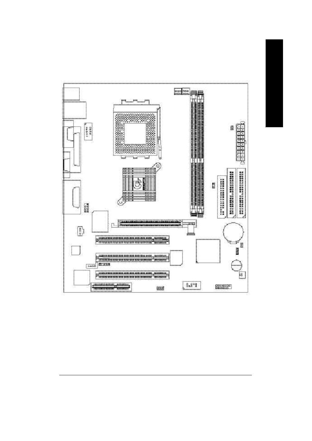
Mother Board
GA-7VKML
is in conformity with
(reference to the specification under which conformity is declared)
in accordance with 89/336 EEC-EMC Directive
o EN 55011 Limits and methods of measurement
of radio disturbance characteristics of
industrial,scientific and medical (ISM
high frequency equipment
o EN 61000-3-2*
T EN 60555-2
Disturbances in supply systems cause
by household appliances and similar
electrical equipment Harmonics
o EN 55013
Limits and methods of measurement
of radio disturbance characteristics of
broadcast receivers and associated
equipment
o EN 61000-3-3* Disturbances in supply systems cause
by household appliances and similar
electrical equipment Voltage fluctuations
o EN 55014 Limits and methods of measurement
of radio disturbance characteristics of
household electrical appliances,
portable tools and similar electrical
apparatus
T EN 50081-1
Generic emission standard Part 1:
Residual commercial and light industry
T EN 50082-1
Generic immunity standard Part 1:
Residual commercial and light industry
o EN 55015 Limits and methods of measurement
of radio disturbance characteristics of
fluorescent lamps and luminaries
Generic emission standard Part 2:
Industrial environment
o EN 55081-2
Immunity from radio interference of
broadcast receivers and associated
equipment
Generic emission standard Part 2:
Industrial environment
o EN 55082-2
T EN 55022 Limits and methods of measurement
of radio disturbance characteristics of
information technology equipment
lmmunity requirements for household
appliances tools and similar apparatus
o ENV 55104
Cabled distribution systems; Equipment
for receiving and/or distribution from
sound and television signals
EMC requirements for uninterruptible
power systems (UPS)
o EN50091-2
o EN 55020
o DIN VDE 0855
o part 10
o part 12
(EC conformity marking)
T CE marking
The manufacturer also declares the conformity of above mentioned product
with the actual required safety standards in accordance with LVD 73/23 EEC
Safety requirements for mains operated
electronic and related apparatus for
household and similar general use
o EN 60950
o EN 60065
Safety of household and similar
electrical appliances
o EN 60335
Manufacturer/Importer
Signature:
Name:
(Stamp)
Date : July 31, 2002
T EN 60555-3
Timmy Huang
Timmy Huang
o EN 50091-1
FCC Part 15, Subpart B, Section 15.107(a) and Section 15.109(a),
Class B Digital Device
DECLARATION OF CONFORMITY
Per FCC Part 2 Section 2.1077(a)
Responsible Party Name:
Address:
Phone/Fax No:
hereby declares that the product
Product Name:
Conforms to the following specifications:
This device complies with part 15 of the FCC Rules. Operation is
subject to the following two conditions: (1) This device may not
cause harmful and (2) this device must accept any inference received,
including that may cause undesired operation.
Representative Person’s Name:
Signature:
Eric Lu
Supplementary Information:
Model Number:
17358 Railroad Street
City of Industry, CA 91748
G.B.T. INC. (U.S.A.)
(818) 854-9338/ (818) 854-9339
Motherboard
GA-7VKML
Date:
ERIC LU
July 31,2002
USERS MANUAL
GA-7VKML Series
AMD Socket A Processor Motherboard
Rev. 3.4 First Edition
12ME-7VKML-3401
- 2 -GA-7VKML Series Motherboard
English
Table of Content
Item Checklist ..................................................................................4
WARNING! .......................................................................................4
Chapter 1 Introduction .......................................................................5
Features Summary................................................................................................ 5
GA-7VKML (PCB Ver.: 1.1) Motherboard Layout ............................................. 7
GA-7VKML (PCB 3.2/3.3/3.4) Motherboard Layout ......................................... 8
Chapter 2 Hardware Installation Process ............................................9
Step 1: Install the Central Processing Unit (CPU) .........................................10
Step1-1: CPU Speed Setup .................................................................................... 10
Step1-2: CPU Installation .........................................................................................11
Step1-3: CPU Heat Sink Installation ......................................................................... 12
Step 2: Install memory modules ....................................................................... 13
Step 3: Install expansion cards .........................................................................15
Step 4: Connect ribbon cables, cabinet wires, and power supply ............. 16
Step4-1: I/O Back Panel Introduction ........................................................................ 16
Step4-2: Connectors Introduction (For PCB Ver. : 3.2 ~ 3.4) ........................................ 18
Step4-3: Connectors Introduction (For PCB Ver. : 1.1) ................................................ 25
Chapter 3 BIOS Setup ....................................................................31
The Main Menu (For example: BIOS Ver. : F9a) .......................................... 32
Standard CMOS Features .................................................................................34
BIOS Features Setup .......................................................................................... 37
Chipset Features Setup ...................................................................................... 39
- 3 -
Table of Content
EnglishEnglish
Integrated Peripherals ........................................................................................ 49
Hardware Monitor & MISC Setup ..................................................................... 53
Set Supervisor / User Password ........................................................................ 55
IDE HDD Auto Detection ..................................................................................... 56
Save & Exit Setup ................................................................................................. 57
Exit Without Saving .............................................................................................. 58
Chapter 4 Technical Reference ........................................................61
Block Diagram ..................................................................................................... 61
@ BIOS
TM
Introduction ........................................................................................ 62
Easy Tune
TM
4 Introduction ............................................................................... 63
Q-Flash Utility Introduction ................................................................................ 64
2-/4-/6-Channel Audio Function Introduction .................................................79
Chapter 5 Appendix ........................................................................ 87
Power Management Setup ................................................................................ 42
PNP/PCI Configuration ....................................................................................... 45
Load Fail-Safe Defaults ...................................................................................... 47
Load Optimized Defaults .................................................................................... 48
- 4 -GA-7VKML Series Motherboard
English
Item Checklist
Computer motherboards and expansion cards contain very delicate Integrated Circuit (IC) chips. To
protect them against damage from static electricity, y ou should follow some precautions whenever
you work on your computer.
1. Unplug your computer when working on the inside.
2. Use a grounded w rist strap before handling computer components. If you do not have
one, touch both of your hands to a safely grounded object or to a metal object, such as
the power supply case.
3. Hold components by the edges and try not touch the IC chips, leads or connectors, or
other components.
4. Place components on a grounded antistatic pad or on the bag that came with the
components whenever the components are separated from the system.
5. Ensure that the ATX pow er supply is switched off before you plug in or remove the ATX
pow er connector on the motherboard.
If the motherboard has mounting holes, but they dont line up with the holes on the base and
there are no slots to attach the spacers, do not become alarmed y ou can still attach the spacers to
the mounting holes. Just cut the bottom portion of the spacers (the spacer may be a little hard to
cut off, so be careful of your hands). In this way y ou can still attach the motherboard to the base
without worrying about short circuits. Sometimes you may need to use the plastic springs to isolate
the screw from the motherboard PCB surface, because the circuit wire may be near by the hole. Be
careful, dont let the screw contact any printed circuit write or parts on the PC B that are near the
fix ing hole, otherwise it may damage the board or cause board malfunctioning.
Installing the motherboard to the chassis
WARNING!
þ The GA-7VKML series motherboard o 2 Port USB Cable x 1
þ IDE cable x 1/ Floppy cable x 1 o 4 Port USB Cable x 1
þ CD for motherboard driver & utility (VUCD) o SPDIF KIT x 1(SPD-KIT)
þ GA-7VKML series users manual o IEEE 1394 Cable x1
þ I/O Shield o Center/Subwoofer Cable x1
o Quick PC Installation Guide (SURROUND-KIT)
o RAID Manual o Motherboard Settings Label
English
Introduction- 5 -
Form Factor 24.4cm x 21.7cm Micro ATX size form factor, 4 layers PCB.
(For PCB Vev.: 1.1)
24.3cm x 21.0cm Micro ATX size form factor, 4 layers PCB.
(For PCB Ver.: 3.2~3.4)
Motherboard GA-7VKML Series Motherboard:
GA-7VKML / GA-7VKML-P / 7VKML-DL
CPU Socket A processor
AMD Athlon
TM
/Athlon
TM
XP/Duron
TM
(K7) Socket A processor
128K L1 & 256K/64K L2 cache on die
Supports 1.4GHz and faster
200/266MHz FSB and DDR bus speeds (PCI 33MHz)
Chipset VIA KM266 Memory/AGP/PCI Controller (PAC)
VIA VT8233A Low cost V-LINK Client Highly Intergated
Memory 2 184-pin DDR DIMM sockets
Supports PC1600 DDR or PC2100 DDR DIMM
Supports up to 2GB DRAM (Max)
Supports only 2.5V DDR DIMM
Supports 64bit DRAM integrity mode
I/O Control IT8705F
Slots 1 AGP slot (2X/4X) device support
3 PCI Slots Supports 33MHz & PCI 2.2 compliant
1 CNR (Communication and Netw orking Riser) Slot
(only secondary card) *
On-Board IDE 2 IDE bus master (ATA66/100/133) IDE ports for up to 4
ATAPI devices
Supports PIO mode3,4 (ATA66/100/133) IDE & ATAPI
CD-ROM
Chapter 1 Introduction
to be continued......
Features Summary
"*" Supported on motherboard version: 1.1 only.
- 6 -GA-7VKML Series Motherboard
English
On-Board Peripherals 1 Floppy port supports 2 FDD with 360K, 720K,1.2M, 1.44M
and 2.88M bytes.
1 Parallel port supports Normal/EPP/ECP mode
2 Serial port (COM A, Internal COM B)
1 VGA port
4 USB ports (Rear USB x 2, Front USB x 2)
1 IrDA connector for IR
Hardware Monitor CPU/System Fan Revolution detect
CPU/System temperature detect
System Voltage Detect
On-Board Sound
#
Realtek ALC101 CODEC
Line In/Line Out/Mic In/CD_In/AUX_In /Game Port
On-Board Sound ** Realtek ALC650 CODEC
Line Out / 2 front speaker
Line In / 2 rear speaker(by s/w switch)
Mic In / center& subwoofer(by s/w switch)
SPDIF out
CD_In/ AUX_IN/Game Port
On-Board LAN *** Build in RTL8100 Chipset
PS/2 Connector PS/2 Keyboard interface and PS/2 Mouse interace
BIOS Licensed AMI BIOS, 2M bit Flash ROM
Support Q-Flash Utility
Additional Features STR(Suspend-To-RAM)
AC Recovery
USB KB/Mouse wake up from S3
PS2 KB/Mouse wake up from S1, S3, S4, S5
Supports @BIOS
TM
Supports Easy Tune
TM
4
M Please set the CPU host frequency in accordance with your processors specifications.
We dont recommend you to set the system bus frequency over the CPUs specification
because these specific bus frequencies are not the standard specifications for C PU,
chipset and most of the peripherals. Whether your system can run under these specific
bus frequencies properly will depend on your hardware configurations, including CPU,
Chipsets,SDRAM,Cards .etc.
" # " Supported 7VKML PCB VER: 3.2 / 3.3 / 3.4.
" ** " Supported GA-7VKML-P / GA-7VKML-DL (PCB VER:3.4)
" *** " Supported 7VKML (PCB VER: 3.2 ~ 3.4 and 7VKML-P)
English
Introduction- 7 -
"**" Supported on motherboard version: 1.1 only. Default doesn’t include the
Shunter to prevent from improper use this jumper. To clear CMOS, temporarily
short 1-2 pin.
GA-7VKML (PCB Ver.: 1.1) Motherboard Layout
MS_ KB
CPU_FAN
ATX
SOCK ET A
USB
COMA
LPT
LAN
VGA
LINE_OUT
CLK_SW
LED1
VT8233A
PCI2
PCI3
USB1
F_PANEL
CNR1
BI OS
RTL8100
KM266
IDE1
IDE2
FDD
DDR1
DDR2
COMB
PCI1
CODEC
CD_IN
BAT1
GAME
LINE_IN
MIC_IN
SYS_FAN
IR
GA-7VKML
F_AUDIO
AG P
IT8705F
WOL
SPDIF
BZ1
CI
S_IRQ
CLR_CMOS**
- 8 -GA-7VKML Series Motherboard
English
GA-7VKML (PCB 3.2/3.3/3.4) Motherboard Layout
MS_ KB
CPU_FAN
ATX
SOCK ET A
USB
COMA
LPT
LAN *
VGALINE_OUT
CLK_JP
RAM_LED
VT8233A
PCI2
PCI3
USB1
F_PANEL
BI OS
RTL
8100 *
KM266
IDE1
IDE2
FDD
DDR1
DDR2
COMB
PCI1
CODEC
CD_IN
BAT1
GAME
LINE_IN
MIC_IN
SYS_FAN
GA-7VKML
F_AUDIO
AG P
IT8705F
IR
BZ1
PWR_LED
AUX_IN
CI
SUR_CEN **
SPDIF ** SPDIF_IN **
- P- DL
" * " Not Supported 7VKML-DL (PCB VER:3.4)
" ** " Supported 7VKML-P / 7VKML-DL (PCB VER:3.4)
English
Introduction- 9 -
To set up your computer, you must complete the following setups:
Step 1- Set system Switch (CLK_SW)...for PCB Ver. 1.1
Step 1- Set system Jumper(CLK_JP)...for PCB Ver. 3.2
Step 2- Install the Central Processing Unit (CPU)
Step 3- Install memory modules
Step 4- Install expansion cards
Step 5- Connect ribbon cables, cabinet wires, and power supply
Step 6- Setup BIOS software
Step 7- Install supporting software tools
Chapter 2 Hardware Installation Process
PCB Ver. 1.1
Step 5
Step 1
Step 3
Step 5
Step 4
Step 2
PCB Ver. 3.2
Step 5
Step 1
Step 3
Step 5
Step 4
Step 2
- 10 -GA-7VKML Series Motherboard
English
Step 1: Install the Central Processing Unit (CPU)
Step1-1: CPU Speed Setup
The sy stem bus frequency can be switched at 100/133MHz by adjusting C LK_SW.
(The frequency ratio depend on C PU.)
Default Setting: 100MHz
1
ON
CLK_SW
CLK_SW
OFF: 133MHz
ON: 100MHz
PCB Ver: 1.1 used
PCB Ver: 3.2 ~ 3.4 used
The sy stem bus frequency can be switched at 100/133MHz by adjusting C LK_JP.
(The frequency ratio depend on C PU.)
1-2 close: 100 MHz
2-3 close: 133 MHz
1
1
Default Setting: 100MHz
English
Hardware Installation Process- 11 -
Step1-2: CPU Installation
M If you do not match the CPU socket Pin 1 and CPU cut edge well, it will cause
improper installation. Please change the insert orientation.
CPU Top View
CPU Bottom View
1. Pull up the CPU socket lever
and up to 90-degree angle.
2. Locate Pin 1 in the socket and look
for a (golden) cut edge on the CPU
upper corner. Then insert the CPU
into the socket.
M Please make sure the CPU type is supported by the motherboard.
Socket Actuation Lever
Pin1 indicator
- 12 -GA-7VKML Series Motherboard
English
Step1-3: CPU Heat Sink Installation
1.Press down the CPU socket
lever and finish CPU installation.
M Please use AMD approved cooling fan.
M We recommend you to apply the thermal paste to provide better heat
conduction between your CPU and heatsink.
M Make sure the CPU fan power cable is plugged in to the CPU fan connector,
this completes the installation.
M Please refer to CPU heat sink users manual for more detail installation procedure.
3.Fasten the heatsink supporting-base
onto the CPU socket on the main-
board.
2.Use qualified fan approved by AMD.
4.Make sure the CPU fan is plugged to
the CPU fan connector, than install
complete.
English
Hardware Installation Process- 13 -
Step 2: Install memory modules
The motherboard has 2 dual inline memory module (DIMM) sockets. The BIOS will automati-
cally detects memory type and size. To install the memory module, just push it vertically into the
DIMM Slot. The DIMM module can only fit in one direction due to the notch. Memory size can vary
between sockets.
Total Memory Sizes With Unbuffered DDR DIMM
Devices used on DIMM 1 DIMMx64/x72 2 DIMMsx64/x72
64 Mbit (2M x8x4 banks) 128 MBytes 256 MBytes
64 Mbit (1Mx 16x4 banks) 64 MBytes 128 MBytes
128 Mbit(4Mx8x4 banks) 256 MBytes 512 MBytes
128 Mbit(2Mx16x4 banks) 128 MBytes 256 MBytes
256 Mbit(8Mx8x4 banks) 512 MBytes 1 GBytes
256 Mbit(4Mx16x4 banks) 256 MBytes 512 MBytes
512 Mbit(8Mx16x4 banks) 512 MBytes 1 GBytes
- 14 -GA-7VKML Series Motherboard
English
1. The DIMM slot has a notch, so the DIMM
memory module can only fit in one direction.
2. Insert the DIMM memory module verticallyinto the
DIMM slot. Then push it down.
3. Close the plastic clip at both edges of theDIMM slots
to lock the DIMM module.
Reverse the installation steps when you wish to
remove the DIMM module.
DDR
M When RAM_LED is ON, do not install/remove DDR from socket.
M Please note that the DIMM module can only fit in one direction due to the two
notches. Wrong orientation will cause improper installation. Please change
the insert orientation.
DDR Introduction
Established on the existing SDRAM industry infrastructure, DDR (Double Data Rate) memory
is a high performance and cost-effectiv e solution that allows easy adoption for memory v endors,
OEMs and system integrators.
DDR memory is a sensible evolutionary solution for the PC industry that builds on the existing
SDRAM infrastructure, yet makes awesome advances in solving the system performance bottle-
neck by doubling the memory bandwidth. DDR SDRAM will offer a superior solution and migration
path from existing SDRAM designs due to its availability, pricing and overall market support. PC2100
DDR memory (DDR266) doubles the data rate through reading and writing at both the rising and
falling edge of the clock, achiev ing data bandwidth 2X greater than PC133 when running with the
same DRAM clock frequency. With peak bandwidth of 2.1GB per second, DDR memory enables
system OEM s to build high performance and low latency DRAM subsystems that are suitable for
servers, w orkstations, high-end PC's and value desktop SMA systems. With a core voltage of only
2.5 Volts compared to conventional SDRAM's 3.3 volts, DDR memory is a compelling solution for
small form factor desktops and notebook applications.
English
Hardware Installation Process- 15 -
Please carefully pull out the small white-
draw able bar at the end of the AGP slot when
you try to install/ Uninstall the AGP card.
Please align the AGP card to the onboard AGP
slot and press firmly down on the slot .Make
sure your AGP card is locked by the small
white- drawable bar.
Issues To Beware Of When Installing CNR (Only for PCB Ver. : 1.1)
Please use standard CNR card like the one in order to avoid mechanical problem.
Standard CNR card
Step 3: Install expansion cards
1. Read the related expansion cards instruction document before install the ex pansion card into
the computer.
2. Remove your computers chassis cover, screws and slot bracket from the computer.
3. Press the expansion card firmly into expansion slot in motherboard.
4. Be sure the metal contacts on the card are indeed seated in the slot.
5. Replace the screw to secure the slot bracket of the expansion card.
6. Replace your computers chassis cover.
7. Power on the computer, if necessary, setup BIOS utility of expansion card from BIOS.
8. Install related driver from the operating system
AGP Card
- 16 -GA-7VKML Series Motherboard
English
Step 4: Connect ribbon cables, cabinet wires, and power
supply
Step4-1: I/O Back Panel Introduction
u PS/2 Keyboard and PS/2 Mouse Connector
ØThis connector supports standard PS/2 keyboard
and PS/2 mouse.
v USB & LAN Connector
Ø Before you connect your device(s) into USB
connector(s), please make sure your device(s)
such as USB keyboard,mouse, scanner, zip,
speaker..etc. Hav e a standard USB interface.
Also make sure your OS supports USB
controller. If y our OS does not support USB
controller, please contact OS vendor for possible
patch or driver upgrade. For more information
please contact your OS or device(s) vendors.
PS/2 Mouse Connector
(6 pin Female)
PS/2 Keyboard Connector
(6 pin Female)
u
v w
x
y
" * " Not Supported 7VKML-DL (PCB VER:3.4)
USB 1
USB 0
LAN *
1 / 1

Gigabyte GA-7VKML User manual

Category
Motherboards
Type
User manual
This manual is also suitable for

Ask a question and I''ll find the answer in the document

Finding information in a document is now easier with AI

Ask the document