Milwaukee Mi 180 User manual
- Category
- Measuring, testing & control
- Type
- User manual

www.milwaukeetesters.com
1
Multiparameter Bench MeterMultiparameter Bench Meter
Multiparameter Bench MeterMultiparameter Bench Meter
Multiparameter Bench Meter
Mi 180
pH/mV/EC/TDS/NaCl/TpH/mV/EC/TDS/NaCl/T
pH/mV/EC/TDS/NaCl/TpH/mV/EC/TDS/NaCl/T
pH/mV/EC/TDS/NaCl/T
emperatureemperature
emperatureemperature
emperature
INSTRUCTION MANUAL
www.milwaukeeinst.com

Instruction Manual Mi 180 Bench Meter
22
22
2
FUNCTIONAL DESCRIPTION ............................................................................................
2
GENERAL DESCRIPTION ................................................................................................... 4
SPECIFICATIONS .............................................................................................................. 5
OPERATIONAL GUIDE ..................................................................................................... 7
AUTORANGING ............................................................................................................. 11
pH CALIBRATION ........................................................................................................... 12
pH BUFFER TEMPERATURE DEPENDENCE ........................................................................ 15
RELATIVE mV CALIBRATION ............................................................................................. 16
EC/TDS CALIBRATION ..................................................................................................... 17
NaCl CALIBRATION ........................................................................................................ 18
GOOD LABORATORY PRACTICE (GLP) ............................................................................ 19
LOGGING .................................................................................................................... 25
SETUP ............................................................................................................................ 33
mV CALIBRATION ........................................................................................................... 35
TEMPERATURE CALIBRATION .......................................................................................... 36
EC SOLUTIONS TEMPERATURE DEPENDENCE ................................................................. 37
PC INTERFACE ............................................................................................................... 38
ELECTRODE CONDITIONING & MAINTENANCE ............................................................. 40
TROUBLESHOOTING ..................................................................................................... 42
ACCESSORIES ................................................................................................................ 43
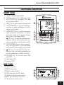
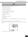
DISPLAYDISPLAY
DISPLAYDISPLAY
DISPLAY
A. PRIMARY DISPLAY
B. MEASURING UNIT FOR PRIMARY
DISPLAY
C. CALIBRATION MESSAGES
D. MEMORIZED pH CALIBRATION
BUFFERS
E. CALIBRATION TAGS
F. GLP TAGS
G. MODE INDICATORS
H. REQUIRE USER CONFIRMATION
I. CALIBRATION REQUESTED
J. SECONDARY DISPLAY
K. MEASURING UNIT FOR SECONDARY
DISPLAY
L. TEMPERATURE COMPENSATION
MODE INDICATOR
M. CALIBRATION MESSAGES
N. MEASURING UNIT FOR PRIMARY
DISPLAY
FUNCTIONAL DESCRIPTION
B
A
C
D
E
G
F
H
I
J
K
L
M
N

www.milwaukeeinst.com
3
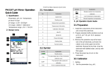
FUNCTIONAL DESCRIPTION
RS 232
POWER
12VDC
USB
EC
TEMP
REF
15
16
17
19
13
14
18
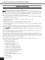
FRONT PANELFRONT PANEL
FRONT PANELFRONT PANEL
FRONT PANEL
1. Liquid Crystal Display (LCD)
2. CAL key, to enter/exit calibration mode
3. GLP/ACCEPT key, to display GLP data
or to confirm value
4. SHIFT key, to select second key function
5. LOG/CLR/MR key, to store reading in
memory, to clear calibration or to en-
ter/exit recall mode
6. MODE/SETUP key, to select measure-
ment mode/pH resolution, to enter/
exit setup mode or to toggle between
delete one or all logged data
7.
/ATC key, to manually decrease tem-
perature value or other parameters or to
select temperature compensation mode
8. RANGE/FIXED key, to switch measure-
ment unit pH/mV/EC or focused data,
or to freeze current reading on the LCD
9.
/TC key, to manually increase tem-
perature value or other parameters or
to view temperature coefficient value
10. ON/OFF key, to turn the meter ON
and OFF
11. Secondary LCD
12. Primary LCD
REAR PANELREAR PANEL
REAR PANELREAR PANEL
REAR PANEL
13. USB connector
14. RS232 connector
15. Power supply socket
16. DIN connector for EC probe
17. Reference pH electrode socket
18. BNC pH electrode connector
19. Temperature probe socket
12
11
10
9
8
7
6
5
4
3
2
1

Instruction Manual Mi 180 Bench Meter
44
44
4
GENERAL DESCRIPTION
Tha
nk you for choosing Milwaukee Instruments. This instruction manual will provide you
the necessary information for correct use of the meter.
Mi
Mi 180
is a logging microprocessor-based pH, ORP, EC, TDS, NaCl and temperature bench meter.
This meter is provided with a series of new diagnostic features which add an entirely
new dimension to the measurement of pH/ORP/EC/TDS/NaCl, by allowing the user to
dramatically improve the reliability of the measurement:
•
7 memorized buffers (pH 1.68, 4.01, 6.86, 7.01, 9.18, 10.01 and 12.45) for pH calibration
• pH calibration up to 3 points
• Messages on the LCD to make the calibration easy and accurate
• Relative mV feature
• GLP feature, to view last calibration data for pH, EC or NaCl
• User-selectable alarm time out to alert the user that too much time elapsed since the
last pH calibration
•
Log-on-demand (50 samples for each range: pH, mV/Rel mV, EC, TDS, NaCl)
Moreover, it offers an extended temperature range from –20 °C (–4 °F) to 120 °C (248°F),
using
MA 831RMA 831R
MA 831RMA 831R
MA 831R interchangeable temperature probe or the temperature sensor inside
the EC probe.
The autoranging feature of the EC and TDS ranges automatically sets the instrument to
the scale with the highest possible resolution.
The conductivity measurements are manually or automatically compensated for tem-
perature effect, with the temperature sensor inside the conductivity probe. It is also
possible to disable the temperature compensation and measure the actual conductivity.
The temperature coefficient is user selectable.
For accurate measurements, use the electrode holder supplied with the meter.
This Bench Meter is supplied with:
• MA 917B/1 pH Electrode
• MA 831R Temperature Probe
• MA 814DB/1 EC/Temperature Probe
• MA 9315 Electrode Holder
• M 10004 pH 4.01 Sachet Buffer Solution
• M 10007 pH 7.01 Sachet Buffer Solution
• M 10010 pH 10.01 Sachet Buffer Solution
• M 10016 Sachet Electrode Cleaning Solution
• M 100 31 1,413 mS/cm Cal Solution Sachet
• M 100 16 Cleaning Solution Sachet
• Mi 5200 Application Software
• MA 9350 RS232 Connector cable (2 meters)
• Graduate Pipet
• 12 VDC Adapter
• Instruction Manual

www.milwaukeeinst.com
5
SPECIFICATIONS
Range pH -2.00 to 16.00 pH / -2.000 to 16.000 pH
mV ±699.9 mV / ±2000 mV
EC 0.00 to 29.99 μS/cm
30.0 to 299.9 μS/cm
300 to 2999 μS/cm
3.00 to 29.99 mS/cm
30.0 to 200.0 mS/cm
up to 500.0 mS/cm (uncompensated EC)*
TDS 0.00 to 14.99 mg/L (ppm)
15.0 to 149.9 mg/L (ppm)
150 to 1499 mg/L (ppm)
1.50 to 14.99 g/L (ppt)
15.0 to 100.0 g/L (ppt)
up to 400.0 g/L (uncompensated TDS)* with 0.80 conversion factor
NaCl 0.0 to 400.0%
Temp -20.0 to 120.0 °C (-4.0 to 248.0 °F)
Resolution pH 0.01 pH / 0.001 pH
mV 0.1 mV / 1 mV
EC 0.01 μS/cm
0.1 μS/cm
1 μS/cm
0.01 mS/cm
0.1 mS/cm
TDS 0.01 mg/L
0.1 mg/L
1mg/L
0.01 g/L
0.1 g/L
NaCl 0.1%
Temp 0.1 °C (0.1 °F)
(
*
)
Uncompensated conductivity (or TDS) is the conductivity (or TDS) value without temperature compensation.

Instruction Manual Mi 180 Bench Meter
66
66
6
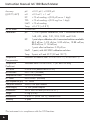
Accuracy pH ±0.01 pH / ±0.002 pH
(@ 20 °C / 68 °F) mV ±0.2 mV / ± 1 mV
EC ±1% of reading ±(0.05 μS/cm or 1 digit)
TDS ±1% of reading ±(0.03 mg/L or 1 digit)
NaCl ±1% of reading
Temp ±0.4 °C (±0.8 °F)
Rel mV offset ±2000 mV
Calibration pH 1, 2 or 3 points calibration, with 7 memorized buffers:
1.68, 4.01, 6.86, 7.01, 9.18, 10.01 and 12.45
EC 1 point slope calibration with 6 memorized solutions available:
84.0 μS/cm, 1413 μS/cm, 5.00 mS/cm, 12.88 mS/cm,
80.0 mS/cm, 111.8 mS/cm;
1 point offset calibration: 0.00 μS/cm
NaCl 1-point, with MA 9050 calibration solution
Temp 2-point, at 0 and 50 °C (32 and 122 °F)
Temperature Automatic or manual, from -20.0 to 120.0 °C (-4.0 to 248.0 °F)
Compensation
Temperature Selectable from 0.00 to 6.00%/ °C (EC and TDS only)
Coefficient
TDS factor 0.40 to 0.80 (default value is 0.50)
pH Electrode MA 917B/1 (included)
Temperature Probe MA 831R (included)
EC Probe MA 814DB/1 (included)
Input Impedance (pH) 10
12
ohms
Computer Interface RS232/USB opto-isolated
Power supply 12 VDC power adapter
Dimensions 230 x 160 x 95 mm (9.0 x 6.3 x 3.7")
Weight 0.9 kg (2.0 lb.)
Environment 0 to 50 °C (32 to 122 °F) ; max RH 95%
Warranty 3 years
This instrument is in compliance with the CE Directives.

www.milwaukeeinst.com
7
OPERATIONAL GUIDE
INITIAL PREPARATIONINITIAL PREPARATION
INITIAL PREPARATIONINITIAL PREPARATION
INITIAL PREPARATION
Plug the 12 VDC adapter to the power supply socket. To prepare the instrument for pH
measurements, connect the pH electrode to the BNC connector and the temperature
probe to the appropriate socket on the rear panel of the instrument. The temperature
probe is used in conjunction with the pH electrode to utilize the instrument's ATC
capability, but it can also be used independently to take temperature measurements.
For electrodes with a separate reference, connect the electrode’s BNC to the BNC
connector and plug the reference electrode to the reference socket.
For temperature measurements and pH automatic temperature compensation connect the
temperature probe to the appropriate socket. After taking measurements switch the meter
off, clean the electrode and store it with a few drops of
MA 9015 MA 9015
MA 9015 MA 9015
MA 9015 storage solution in the
protection cap.
For EC/TDS measurements connect the EC probe to the 7-pin connector. Make sure the
probe sleeve is properly inserted and tighten the threaded ring.
The instrument enters the same range and mode as it was at power off
.
For pH and mV/Rel mV
modes, after turning the instrument on, the “OPEN” tag and the “
” and “ ” symbols from the
electrode blink on the LCD for a few seconds to remind the user to unscrew the electrode
refilling cap, and to remove the protective cap before taking measurements.
pHpH
pHpH
pH
MEASUREMENTS MEASUREMENTS
MEASUREMENTS MEASUREMENTS
MEASUREMENTS
Make sure the instrument has been calibrated before taking pH measurements.
• If necessary, press the RANGE key until the display changes to pH mode.
• Submerge the tip of the electrode (4cm/1½") and the temperature probe into the sample
to be tested and stir gently. Allow for the electrode to stabilize.
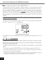
• The pH measurement is displayed on the primary LCD and the temperature on the secondary LCD.
• If the reading is out of range, the closest full-scale value will blink on the primary LCD.

Instruction Manual Mi 180 Bench Meter
88
88
8
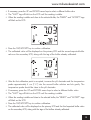
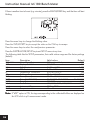
The display will show the default temperature of 25 °C or the last temperature reading with
the “MTC” tag and “°C” (or “°F”) tag blinking.
The temperature can now be adjusted with the UP and DOWN arrow keys (from –20.0 °C to
120.0 °C).
mm
mm
m
V / REL V / REL
V / REL V / REL
V / REL
mm
mm
m
V MEASUREMENTSV MEASUREMENTS
V MEASUREMENTSV MEASUREMENTS
V MEASUREMENTS
An optional ORP electrode must be used to perform ORP measurements (see “Accessories” section).
Oxidation-Reduction Potential (ORP) measurements provide the quantification of the oxidizing or
reducing power of the tested sample.
To perform an ORP measurement correctly, the surface of the electrode must be clean and
smooth.
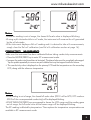
• If necessary, press the RANGE/FIXED key until the display changes to mV/Rel mV.
• Submerge the ORP electrode tip (4cm/1½") into the sample to be tested and allow a
few seconds for the reading to stabilize.
• The instrument displays the mV reading on the primary LCD or Rel mV reading if a Rel mV
calibration has been performed and the temperature on the secondary LCD.
NoteNote
NoteNote
Note: To change pH resolution press the MODE/SETUP key.
If measurements are taken successively in different samples, it is recommended to rinse the
electrode thoroughly with deionizated water and then with some of the sample to be tested.
The pH reading is affected by temperature. In order to measure the pH accurately, the
temperature effect must be compensated. To use the Automatic Temperature Compensation
(ATC) feature, connect and submerge the
MA 831RMA 831R
MA 831RMA 831R
MA 831R temperature probe into the sample as
close as possible to the electrode and wait for a few seconds. The “ATC” tag will be
displayed.
If Manual Temperature Compensation (MTC) is desired, the temperature probe must be
disconnected from the instrument.

www.milwaukeeinst.com
9
NotesNotes
NotesNotes
Notes:
•When the reading is out of range, the closest full-scale value is displayed blinking.
•
If using a pH electrode while in mV mode, the instrument will measure the mV generated
by the pH electrode.
•If the instrument displays a Rel mV reading and it is desired to take mV measurements,
simply clear the Rel mV calibration (see Rel mV calibration section at page 16).
CONDUCTIVITYCONDUCTIVITY
CONDUCTIVITYCONDUCTIVITY
CONDUCTIVITY
MEASUREMENTS MEASUREMENTS
MEASUREMENTS MEASUREMENTS
MEASUREMENTS
Make sure the instrument has been calibrated before taking conductivity measurements.
• Press the RANGE/FIXED key to enter EC measurement mode.
• Immerse the probe into the solution to be tested. The sleeve holes must be completely submerged.
Tap the probe repeatedly to remove any air bubbles that may be trapped inside the sleeve.
• The conductivity value is displayed on the primary LCD and the temperature on the secondary
LCD, along with the reference temperature.
NotesNotes
NotesNotes
Notes:
•If the reading is out of range, the closest full-scale value (200.0 mS for MTC/ATC mode or
500.0 mS for uncompensated conductivity) will be displayed blinking.
•I
f SHIFT&RANGE/FIXED keys are pressed to freeze the LCD range and the reading goes
out of range, the full-scale value of the frozen range will be displayed blinking.
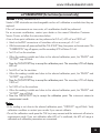
The EC reading is affected by temperature. Three options for temperature compensation are
available in EC measurement mode.
or

Instruction Manual Mi 180 Bench Meter
1010
1010
10
NoteNote
NoteNote
Note: The compensation is referenced at the selected reference temperature (see
SETUP for details, page 33).
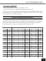
Automatic (ATC): The EC probe has a built-in temperature sensor; the temperature value is
used to automatically compensate the EC/TDS reading (from -20.0 – 120.0 °C).
Manual (MTC): The temperature value, shown on the secondary LCD, can be manually set
with the UP and DOWN arrow keys. The “°C” tag blinks when this option is active.
No Compensation (NOTC): The temperature value is displayed, but it is not taken
into account. The reading displayed on the primary LCD is the uncompensated EC or TDS
value. To select the desired option, press the SHIFT&
/ATC keys until the option is
displayed on the LCD.
NotesNotes
NotesNotes
Notes:
•The default compensation mode is ATC.
•If no temperature probe is detected, ATC mode can not be selected and the instru-
ment displays “----” on the secondary LCD.
If temperature compensation is active, measurements are compensated using the tem-
perature coefficient (default value 1.90 %/°C). To change the temperature coefficient,
enter the setup mode and select the “tc” item (see SETUP for details, page 33). The
current temperature coefficient can be quickly viewed by pressing the SHIFT&
/TC keys.
The value is briefly displayed on the secondary LCD.
• If the temperature reading is out of the -20.0 to 120.0 °C (-4.0 to 248.0 °F) interval and ATC
option is selected, the “°C” tag will blink and the closest interval limit will be displayed.
• By pressing the UP and DOWN arrow keys the displayed temperature value can be
changed. This value is used to compensate the EC/TDS reading.
TDSTDS
TDSTDS
TDS
MEASUREMENTS MEASUREMENTS
MEASUREMENTS MEASUREMENTS
MEASUREMENTS
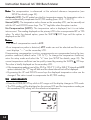
• Press the MODE/SETUP key while in EC range until the display changes to TDS mode.
• The TDS reading will be displayed on the primary LCD and the temperature reading on
the secondary LCD, along with the reference temperature.

www.milwaukeeinst.com
11
NotesNotes
NotesNotes
Notes:
•If the reading is out of range, the full-scale value (160.0 g/L for MTC/ATC mode or
400.0 g/L for uncompensated TDS) will be displayed blinking.
•I
f the SHIFT&RANGE/FIXED keys are pressed to freeze the LCD range and the reading
goes out of range, the full-scale value of the frozen range will be displayed blinking.
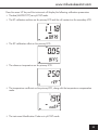
NaClNaCl
NaClNaCl
NaCl
MEASUREMENTS MEASUREMENTS
MEASUREMENTS MEASUREMENTS
MEASUREMENTS
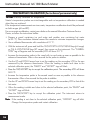
• Press the MODE/SETUP key while in EC range to enter NaCl measurement mode.
• The instrument will display the NaCl reading on the primary LCD and the temperature on the
secondary LCD, along with the reference temperature.
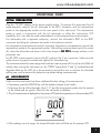
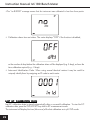
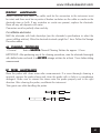
AUTORANGING
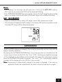
The EC and TDS scales are autoranging. The meter automatically sets the scale with the
highest possible resolution.
By pressing the SHIFT&RANGE/FIXED keys, the autoranging feature is disabled and the
current range is frozen on the LCD. The “Auto” “OFF” (autoranging disabled) message
will be displayed on the LCD for a few seconds. To restore the autoranging option,
press the SHIFT&RANGE/FIXED keys again. The “Auto” “On” (autoranging enabled)
message will be displayed on the LCD for a few seconds.
NoteNote
NoteNote
Note: Autoranging is automatically restored if the range is changed, if the setup or
calibration modes are entered and if the meter is turned off and back on again.

Instruction Manual Mi 180 Bench Meter
1212
1212
12
pH CALIBRATION
It is recommended to calibrate the instrument frequently, especially if high accuracy is required.
The pH calibration is also necessary in the following cases:
a) Whenever the pH electrode is replaced.
b) At least once a week.
c) After testing aggressive chemicals.
d) When extreme accuracy is required.
e) If “CALIBRATION EXPIRED” tag is blinking during measurement.
Every time you calibrate the instrument use fresh buffers and perform an electrode Cleaning
Procedure (see page 41).
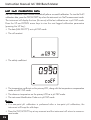
PROCEDUREPROCEDURE
PROCEDUREPROCEDURE
PROCEDURE
One, two or three points calibration can be performed, from the 7 memorized buffers (1.68,
4.01, 6.86, 7.01, 9.18, 10.01 and 12.45 pH).
• Pour small quantities of selected buffer solutions into clean beakers. For accurate calibration
use two beakers for each buffer solution, the first one to rinse the electrode and the second
one for calibration.
• Remove the protective cap and rinse the electrode with some of the buffer solution to be
used for the first calibration point.
THREE-POINT CALIBRATIONTHREE-POINT CALIBRATION
THREE-POINT CALIBRATIONTHREE-POINT CALIBRATION
THREE-POINT CALIBRATION
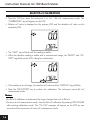
• Immerse the pH electrode and the temperature probe approximately 4 cm (1½”) into a buffer
solution of your choice (pH 1.68, 4.01, 6.86, 7.01, 9.18, 10.01 or 12.45) and stir gently. The
temperature probe should be close to the pH electrode.
•
Press the CAL key. The “CAL”, “1” and “CALIBRATION” tags will appear and the
secondary LCD will display buffer “7.01”.

www.milwaukeeinst.com
13
• If necessary, press the UP and DOWN arrow keys to select a different buffer value.
• The “WAIT” tag will blink on the LCD until the reading is stable.
• When the reading is stable and close to the selected buffer, the “READY” and “ACCEPT” tags
will blink on the LCD.
• Press the GLP/ACCEPT key to confirm calibration.
• The calibrated value will be displayed on the primary LCD and the second expected buffer
value on the secondary LCD, along with the tag of the buffer already calibrated.
• After the first calibration point is accepted, immerse the pH electrode and the temperature
probe approximately 4 cm (1½”) into the second buffer solution and stir gently. The
temperature probe should be close to the pH electrode.
• If necessary, press the UP and DOWN arrow keys to select a different buffer value.
• The “WAIT” tag will blink on the LCD until the reading is stable.
• When the reading is stable and close to the selected buffer, the “READY” and “ACCEPT” tags
will blink on the LCD.
• Press the GLP/ACCEPT key to confirm calibration.
• The calibrated value will be displayed on the primary LCD and the third expected buffer value
on the secondary LCD, along with the tags of the buffers already calibrated.

Instruction Manual Mi 180 Bench Meter
1414
1414
14
• After the second calibration point is accepted, immerse the pH electrode and the tempera-
ture probe approximately 4 cm (1½”) into the third buffer solution and stir gently. The
temperature probe should be close to the pH electrode.
• If necessary, press the UP and DOWN arrow keys to select a different buffer value.
• The “WAIT” tag will blink on the LCD until the reading is stable.
• When the reading is stable and close to the selected buffer, the “READY” and “ACCEPT” tags
will blink on the LCD.
• Press the GLP/ACCEPT key to confirm calibration.
• The instrument stores the calibration values and returns to normal measurement mode.
NotesNotes
NotesNotes
Notes:
•The instrument automatically skips the buffers already used for the previous calibration points to
avoid erroneous procedure.
•If the value measured by the instrument is not close to the selected buffer, “WRONG BUFFER”
and “WRONG PROBE” messages will blink alternately. In this case, check if the correct buffer
has been used or regenerate the electrode by following the Cleaning Procedure (see page 40).
If necessary, change the buffer or the electrode.
•If “WRONG BUFFER” and “Old” messages on the secondary LCD are displayed blinking, an
inconsistency between new and previous (old) calibration is detected. Clear calibration
parameters by pressing the LOG/CLR/MR key and proceed with calibration from the current
calibration point (the instrument will keep all confirmed values during current calibration).
•The “WRONG BUFFER” message and the temperature value blink if temperature reading is
out of the defined temperature range for the buffer. Calibration cannot be confirmed in this
situation.
•Press the RANGE/FIXED key to display the temperature reading during calibration.
•To clear a previous calibration and return to the default values, press the LOG/CLR/MR key at
any time after entering calibration mode. The LCD will show “CLr CAL” for one second, and then
the meter will return to normal measurement mode.

www.milwaukeeinst.com
15
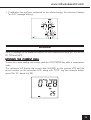
1 OR 2 POINT CALIBRATION
• Proceed as described in “Three-point calibration” section.
• Press the CAL key after the appropriate calibration point is accepted.
The instrument will return to measurement mode, will memorize the calibration data, and the
appropriate tags for the calibrated buffers will be displayed on the LCD only if the “disp” option
from the SETUP menu is ON (see page 33)
.
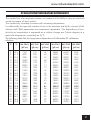
pH BUFFER TEMPERATURE DEPENDENCE
The temperature has an effect on pH. The calibration buffer solutions are affected by temperature
changes to a lesser degree than normal solutions. During calibration the instrument will
automatically calibrate to the pH value corresponding to the measured or set temperature.
During calibration the instrument will display the pH buffer value at 25 °C.
TEMP pH BUFFERS
°C °F
1.68 4.01 6.86 7.01 9.18 10.01 12.45
032
1.67 4.01 6.98 7.13 9.46 10.32 13.38
541
1.67 4.00 6.95 7.10 9.39 10.24 13.18
10 50
1.67 4.00 9.92 7.07 9.33 10.18 12.99
15 59
1.67 4.00 6.90 7.05 9.27 10.12 12.80
20 68
1.68 4.00 6.88 7.03 9.22 10.06 12.62
25 77
1.68 4.01 9.86 7.01 9.18 10.01 12.45
30 86
1.68 4.02 6.85 7.00 9.14 9.96 12.29
35 95
1.69 4.03 6.84 6.99 9.11 9.92 12.13
40 104
1.69 4.04 6.84 6.98 9.07 9.88 11.98
45 113
1.70 4.05 6.83 6.98 9.04 9.85 11.83
50 122
1.71 4.06 6.83 6.98 9.01 9.82 11.70
55 131
1.72 4.08 6.84 6.98 8.99 9.79 11.57
60 140
1.72 4.09 6.84 6.98 8.97 9.77 11.44
65 149
1.73 4.11 6.84 6.99 8.95 9.76 11.32
70 158
1.74 4.12 6.85 6.99 8.93 9.75 11.21
75 167
1.76 4.14 6.86 7.00 8.91 9.74 11.10
80 176
1.77 4.16 6.87 7.01 8.89 9.74 11.00
85 185
1.78 4.17 6.87 7.02 8.87 9.74 10.91
90 194
1.79 4.19 6.88 7.03 8.85 9.75 10.82
95 203
1.81 4.20 6.89 7.04 8.83 9.76 10.73

Instruction Manual Mi 180 Bench Meter
1616
1616
16
RELATIVE mV CALIBRATION
• Press the CAL key when the instrument is in mV / Rel mV measurement mode. The
“CALIBRATION” tag will appear on the LCD.
• Relative mV value is displayed on the primary LCD and the absolute mV value on the
secondary LCD.
• The “WAIT” tag will blink until the reading is stable.
• When the absolute reading is stable and in measurement range, the “READY” and “AC-
CEPT” tags blink on the LCD, asking for confirmation.
• If the reading is out of range, the absolute mV value and the “WRONG” tag will blink.
• Press the GLP/ACCEPT key to confirm the calibration. The instrument enters Rel mV
measurement mode.
NotesNotes
NotesNotes
Notes:
•If a Rel mV calibration is performed, the range changes from mV to Rel mV.
•To return to mV measurement mode, clear the Rel mV calibration by pressing LOG/CLR/MR
after entering calibration mode. The “CLr CAL” message will appear on the LCD for one
second and the instrument will enter mV measurement mode.

www.milwaukeeinst.com
17
EC/TDS CALIBRATION
EC calibration is a one-point procedure. Selectable calibration points are 0.00 μS for
offset and 84.0 μS, 1413 μS, 5.00 mS, 12.88 mS, 80.0 mS, 111.8 mS for slope.
Rinse the probe with calibration solution or deionized water. Immerse the probe into the
solution. The sleeve holes must be completely submerged. Tap the probe repeatedly to
remove any air bubbles that may be trapped inside the sleeve.
To enter EC calibration, select the EC range and press CAL.
NoteNote
NoteNote
Note: The TDS reading is automatically derived from the EC reading and no specific
calibration for TDS is needed. Pressing CAL when TDS range is selected has no
effect.
For zero calibration, just leave the dry probe in the air. This calibration is performed in order
to correct the reading around 0.00 μS. The slope is evaluated when the calibration is
performed in any other point.
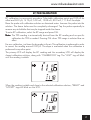
The primary LCD will display the EC reading and the secondary LCD will display the
closest calibration solution, along with “CALIBRATION” tag. The “WAIT” tag will blink
until the reading is stable.
When the reading is stable and close to the selected calibration solution, “READY” and
“ACCEPT” tags will blink on the LCD.

Instruction Manual Mi 180 Bench Meter
1818
1818
18
Press the GLP/ACCEPT key to confirm calibration.
The instrument stores the calibration value and returns to measurement mode.
NotesNotes
NotesNotes
Notes:
•If the uncalibrated reading is too far from the expected value, the “WRONG” and
“SOLUTION” tags will blink. Calibration can not be confirmed. In this case check if
the correct calibration solution has been used.
• If the meter is in ATC mode and the solution temperature is out of the 0.0 to 60.0 °C
(32.0 to 140.0 °F) interval, the “WRONG” “SOLUTION” “°C” tags and the temperature
will be displayed blinking.
• For best results choose an EC calibration solution value close to the sample to be
measured.
• It is possible to set the cell constant value directly, without following the calibration
procedure. To set the cell constant, enter SETUP mode and select “CELL” (see SETUP
for details, page 33).
NaCl CALIBRATION
NaCl calibration is a one-point procedure at 100.0% NaCl. Use the MA 9050
calibration solution (sea water solution) as a 100% NaCl standard solution.
Rinse the probe with some of the calibration solution or deionized water. Immerse the
probe into the MA 9050 solution. The sleeve holes must be completely submerged.
Tap the probe repeatedly to remove any air bubbles that may be trapped inside the
sleeve.
To enter NaCl calibration select the NaCl range and press CAL.
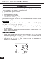
The primary LCD will display the NaCl reading in percentage and the secondary LCD will
display “100”, along with “CALIBRATION” tag. The “WAIT” tag will blink until the
reading is stable.

www.milwaukeeinst.com
19
GOOD LABORATORY PRACTICE (GLP)
GLP is a set of functions that allows storage and retrieval of calibration data and electrode status.
All data regarding pH, EC and NaCl calibration is stored for the user to review when necessary.
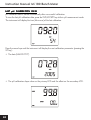
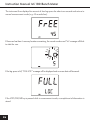
CALIBRATION ALARM TIME-OUTCALIBRATION ALARM TIME-OUT
CALIBRATION ALARM TIME-OUTCALIBRATION ALARM TIME-OUT
CALIBRATION ALARM TIME-OUT
For pH calibration, Mi 180 allows the user to set the number of days (1 to 14) before the next
required calibration. The default setting is OFF (disabled).
The instrument checks the time-out and if the time elapsed, the “CALIBRATION EXPIRED”
message will blink as a reminder.
NoteNote
NoteNote
Note: If the instrument is not calibrated, the “CALIBRATION EXPIRED” message will be
displayed even if the calibration time-out feature is disabled in SETUP menu.
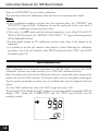
When the reading is stable, the “READY” and “ACCEPT” tags will blink on the LCD.
Press the GLP/ACCEPT key to confirm calibration. The instrument stores the calibration
value and returns to measurement mode.
NotesNotes
NotesNotes
Notes:
•If the reading is too far from the expected value, the “WRONG” and “SOLUTION”
tags will blink. Calibration cannot be confirmed.
• If the temperature of the buffer is out of the 0.0 – 60.0 °C (32.0 – 140.0 °F)
temperature interval, the “WRONG” “SOLUTION”, “°C” tags and temperature will
be displayed blinking.
•
If a new EC calibration is performed, the NaCl calibration is automatically cleared.
Thus, a new NaCl calibration is required.

Instruction Manual Mi 180 Bench Meter
2020
2020
20
LAST LAST
LAST LAST
LAST
pp
pp
p
H CALIBRATION DATAH CALIBRATION DATA
H CALIBRATION DATAH CALIBRATION DATA
H CALIBRATION DATA
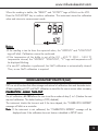
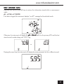
pH calibration data is stored automatically after a successful calibration.
To view the last p
H calibration data, press the GLP/ACCEPT key while in pH measurement mode.
The instrument will display the time (hh:mm:ss) of the last calibration.
Press the arrow keys and the instrument will display the next calibration parameter (pressing the
UP key):
• The date (MM.DD.YYYY).
• The pH calibration slope value on the primary LCD and the offset on the secondary LCD.
Page is loading ...
Page is loading ...
Page is loading ...
Page is loading ...
Page is loading ...
Page is loading ...
Page is loading ...
Page is loading ...
Page is loading ...
Page is loading ...
Page is loading ...
Page is loading ...
Page is loading ...
Page is loading ...
Page is loading ...
Page is loading ...
Page is loading ...
Page is loading ...
Page is loading ...
Page is loading ...
Page is loading ...
Page is loading ...
Page is loading ...
Page is loading ...
-
 1
1
-
 2
2
-
 3
3
-
 4
4
-
 5
5
-
 6
6
-
 7
7
-
 8
8
-
 9
9
-
 10
10
-
 11
11
-
 12
12
-
 13
13
-
 14
14
-
 15
15
-
 16
16
-
 17
17
-
 18
18
-
 19
19
-
 20
20
-
 21
21
-
 22
22
-
 23
23
-
 24
24
-
 25
25
-
 26
26
-
 27
27
-
 28
28
-
 29
29
-
 30
30
-
 31
31
-
 32
32
-
 33
33
-
 34
34
-
 35
35
-
 36
36
-
 37
37
-
 38
38
-
 39
39
-
 40
40
-
 41
41
-
 42
42
-
 43
43
-
 44
44


Milwaukee Mi 180 User manual
- Category
- Measuring, testing & control
- Type
- User manual
Ask a question and I''ll find the answer in the document
Finding information in a document is now easier with AI
Related papers


Other documents
-
Hanna Instruments HI98191 User manual
-
 SimPure TDS Meter Digital Water Tester, TDS Meter, EC Meter & Temperature Meter 3 in 1, User guide
-
-
-
-
-
-
 NESA PH310T pH Meter User guide
-
Oakton TDS 6 User manual
-

