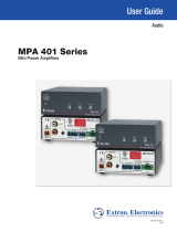
FSR FSR-IT-VCM Owner's manual

Category
Musical Equipment
Type
Owner's manual

FSR FSR-IT-VCM is a stereo or mono line level volume control module that can be controlled remotely via RS-232 commands or with a potentiometer or buttons. It features adjustable bass, treble, and balance, a mute function with LED indicator, and a 0-10V ramp output for driving a bar graph display. It can be used in various applications, such as home theater systems, audio source muting, or remote volume control. Multiple units can be daisy-chained together, and it can also be integrated with other serial controlled devices through its serial loop through port.

FSR FSR-IT-VCM is a stereo or mono line level volume control module that can be controlled remotely via RS-232 commands or with a potentiometer or buttons. It features adjustable bass, treble, and balance, a mute function with LED indicator, and a 0-10V ramp output for driving a bar graph display. It can be used in various applications, such as home theater systems, audio source muting, or remote volume control. Multiple units can be daisy-chained together, and it can also be integrated with other serial controlled devices through its serial loop through port.

Operating Guide
INTELLI-TOOLS
IT- VCM
ASCII or Hardwire Controlled Line Level Volume Control Module
with Serial Loop Through
244 Bergen Blvd West Paterson NJ 07424 1-800-332-FSR1 http://www.fsrinc.com/
43934 LIT1248
2
Warranty Policy
This product is warranted against failures due to defective parts or faulty workmanship for a
period of five years after delivery to the original owner. During this period, FSR will make any
necessary repairs or replace the unit without charge for parts or labor. Shipping charges to the
factory or repair station must be prepaid by the owner, return-shipping charges, via UPS / FedEx
ground, will be paid by FSR.
This warranty applies only to the original owner and is not transferable. In addition, it does not
apply to repairs done by other than the FSR factory or Authorized Repair Stations.
This warranty shall be cancelable by FSR at its sole discretion if the unit has been subjected to
physical abuse or has been modified in any way without written authorization from FSR. FSR’s
liability under this warranty is limited to repair or replacement of the defective unit.
FSR will not be responsible for incidental or consequential damages resulting from the use or
misuse of its products. Some states do not allow the exclusion of incidental or consequential
damages, so the above limitations may not apply to you. This warranty gives you specific legal
rights, and you may also have other rights which vary from state to state.
Warranty claims should be accompanied by a copy of the original purchase invoice showing the
purchase date (if a Warranty Registration Card was mailed in at the time of purchase, this is not
necessary). Before returning any equipment for repair, please read the important information on
service below.
SERVICE
Before returning any equipment for repair, please be sure that it is adequately packed and
cushioned against damage in shipment, and that it is insured. We suggest that you save the
original packaging and use it to ship the product for servicing. Also, please enclose a note giving
your name, address, phone number and a description of the problem.
NOTE: all equipment being returned for repair must have a Return authorization (RMA)
Number. To get a RMA Number, please call FSR Tech Support (973-785-4347). Please
display your RMA Number prominently on the front of all packages.
CONTACT INFORMATION
FSR Inc.
244 Bergen Blvd.
West Paterson, NJ 07424
Phone: (973) 785-4347
*Order Desk Fax: (973) 785-4207
E-mail:
Web Site: http://www.fsrinc.com
3
Table of Contents
Warranty Policy .............................................................................................................................. 2
Table of Contents............................................................................................................................ 3
Product Overview ........................................................................................................................... 4
IT-VCM Dimensions ...................................................................................................................... 5
Typical Applications....................................................................................................................... 6
IT- VCM Operation ........................................................................................................................ 7
Dipswitch Settings .......................................................................................................................... 8
Audio Pinout and Wiring................................................................................................................ 9
IT-VCM Specifications................................................................................................................. 11
4
Product Overview
The IntelliTools IT-VCM is a stereo or mono line level volume control module. The IT-VCM
accepts a balanced or unbalanced stereo audio line level source and provides a balanced stereo
output. The module is able to sum the stereo inputs to mono.
The unit can be used in any application where remote control of the audio level is desired, such
as between the pre-out and main-in jacks of integrated amplifiers or receivers that were built
without remote control.
The IT-VCM responds to RS-232 commands, including volume up/down ramping, audio levels,
treble, balance, bass, muting and serial loop output port baud rate. The IT-VCM can provide
feedback on all the above as well as dip switch, pro/consumer, stereo/mono and pot enable
settings status.
Switches control only volume up/down and mute. They may be used concurrently with serial
control.
The potentiometer can be used for volume control only. In this mode, the volume up and volume
down button terminals as well as the Volume serial commands are disabled. (See IT-VCM
Operation for details)
The module delivers a 0- 10v ramp output that can drive a bar graph indicator (not provided). A
mute output is also provided to drive an LED.
To control multiple sources, the IT-VCM modules can be "daisy-chained," This means that with
only one source you can change the volume level in the different rooms individually. Most RS-
232 devices including FSR’s other IntelliTools modules can also be controlled.
Flanges on the base, along with the supplied screws, permit easy mounting to flat surfaces.
The versatility of the IntelliTools family is limited only by your imagination
5
IT-VCM Dimensions
OUTIN
+
STEREO VOLUME CONTROL
Pot ControlOutputInput Level
4
MUTE 'ON'
INDICATOR
POT HI
Enable
0-10V RAMP
3
INPUTS
POT
Disable
3
AUDIO OUT
RIGHTLEFT
+
SH
-
+
-
Switch
Position
21
Mono L+R
Stereo
AUDIO IN
LEFT RIGHT
-
+
-
SH
+
OUTPUTS
SWITCH
EXTERNAL
MUTE LED
MUTE
DOWN
UP
GND
WIPER
SERIAL ACTIVITY
IN
OUT
Rx
TxTx
Rx
SERIAL
Tx
RxRx
SERIAL
Tx
POWER
12VDC/0.2A
12
Consumer
Pro
NTELLI- OOLS
IT-VCMMODEL:
.22 .22
5.25
5.69
4x .203 DIA.
.22
3.00
.22
3.44
1.57
6
Typical Applications
Typical Applications include:
Home Theater
Audio Source Muting
Audio level status
Remote volume control
Up to five IT-VCM’s can be daisy chained together
NOTE: Multiple serial controlled devices can be daisy chained together through a serial
loop through port without sacrificing a control port on the control system.
OUTIN
+
STEREO VOLUME CONTROL
Pot ControlOutputInput Level
4
MUTE 'ON'
INDICATOR
POT HI
Enable
0-10V RAMP
3
INPUTS
POT
Disable
3
AUDIO OUT
RIGHTLEFT
+
SH
-
+
-
Switch
Position
21
Mono L+R
Stereo
AUDIO IN
LEFT RIGHT
-
+
-
SH
+
OUTPUTS
SWITCH
EXTERNAL
MUTE LED
MUTE
DOWN
UP
GND
WIPER
SERIAL ACTIVITY
IN
OUT
Rx
TxTx
Rx
SERIAL
Tx
RxRx
SERIAL
Tx
POWER
12VDC/0.2A
12
Consumer
Pro
NTELLI- OOLS
IT-VCMMODEL:
TO AC POWER - AC
ADAPTER SOLD
SEPARATELY
MODEL: IT-PS1
FSR PN: 16805
OR
RN-WPCS, HOST PC
OR OTHER CONTROL
SYSTEM SERIAL PORT
RS-232
STEREO
RECEIVER
OUTIN
+
STEREO VOLUME CONTROL
Pot ControlOutputInput Level
4
MUTE 'ON'
INDICATOR
POT HI
Enable
0-10V RAMP
3
INPUTS
POT
Disable
3
AUDIO OUT
RIGHTLEFT
+
SH
-
+
-
Switch
Position
21
Mono L+R
Stereo
AUDIO IN
LEFT RIGHT
-
+
-
SH
+
OUTPUTS
SWITCH
EXTERNAL
MUTE LED
MUTE
DOWN
UP
GND
WIPER
SERIAL ACTIVITY
IN
OUT
Rx
TxTx
Rx
SERIAL
Tx
RxRx
SERIAL
Tx
POWER
12VDC/0.2A
12
Consumer
Pro
NTELLI- OOLS
IT-VCMMODEL:
SERIAL LOOP OUT
AUDIO
SOURCE
SERIAL LOOP OUT TO
ADDITIONAL IT-VCM UNITS
OR OTHER SERIAL
CONTROLLED DEVICE
OR
EXTERNAL
SWITCH
7
IT- VCM Operation
The IT- VCM audio input and output may be wired for balanced or unbalanced applications.
Bridging inputs allow either high or low impedance sources. The output is line-level, low-
impedance balanced.
Depending on the “POT CONTROL” dipswitch setting, the IT- VCM can be set for two
operating modes. When set to DISABLE, the audio level is controlled by normally open
momentary pushbuttons (not provided) connected to the SWITCH INPUT terminals for ramp up
and ramp down the audio level. If either button is held in, the audio level will ramp
automatically. If a button is pulsed (< ½ second), the audio level will increment or decrement
one step. In this mode theVolume serial commands can also be used to control the volume level.
When the “POT CONTROL” dipswitch is set to ENABLE, the potentiometer terminals are
activated and the audio level is controlled by a remote 10 k linear taper pot or by an externally
applied 0 to 12 VDC. In this mode, the volume up and volume down button terminals as well as
the Volume serial commands are disabled
Terminals provide a 0 to 10 VDC output ramp. The ramp output can be used to drive an LED
bar graph display to indicate the current audio level.
A momentary closure between the MUTE and GROUND terminals will mute the audio source.
A second closure will un-mute (toggle action). An on board LED and an LED output terminal
indicate when the IT- VCM audio level is muted.
Settings retention: All current settings are saved in non-volatile flash memory upon power loss.
Settings include: Volume, Bass, Treble, Balance, Mute and settings
There are additional control features such as bass, balance and treble adjustments that are
available through the RS-232 control input and are discussed in the RS-232 protocol section.
8
Dipswitch Settings
8
7
6
5
4
3
2
1
10k
POT
POT HI
WIPER
GND
MUTE
MUTE LED
8
7
6
5
4
3
2
1
GND
VOL-UP
VOL-DN
MUTE
* 0-10v RAMP OUTPUT
MUTE LED
SWITCH 3 - POT DISABLED
THIS CONFIGURATION ALLOWS FOR THE
USE OF MOMENTARY PUSH BUTTONS
FOR CONTROLLING THE VOLUME.
SWITCH 3 - POT ENABLED
THIS CONFIGURATION ALLOWS FOR
THE USE OF AN ADJUSTABLE 10k
POT TO CONTROL THE VOLUME.
OR
* 0-10 VOLT RAMP - BUFFERED OUTPUT THAT INDICATES VOLUME LEVEL USED
FOR DRIVING A BAR GRAPH OR FOR PROVIDING FEEDBACK
TO A CONTROL SYSTEM DESIGNED TO DRIVE A 10k ohm LOAD.
9
Audio Pinout and Wiring
U
T
P
U
T
O
IT-VCM AUDIO OUTPUT CONNECTOR WIRING
TO A STEREO UNBALANCED
PREAMP INPUT
SIGNAL
FLOW
U
T
P
U
T
O
TO A MONO UNBALANCED
PREAMP INPUT
SIGNAL
FLOW
U
T
P
U
T
O
TO A STEREO BALANCED
PREAMP INPUT
SIGNAL
FLOW
U
T
P
U
T
O
SIGNAL
FLOW
TO A MONO BALANCED
PREAMP INPUT
IT-VCM AUDIO INPUT CONNECTOR WIRING
FROM A STEREO
UNBALANCED SOURCE
SIGNAL
FLOW
FROM A MONO
UNBALANCED SOURCE
SHIELD
SIGNAL
FLOW
FROM A STEREO BALANCED
SOURCE
SIGNAL
FLOW
SIGNAL
FLOW
FROM A MONO BALANCED
SOURCE
I
N
P
U
T
I
N
P
U
T
I
N
P
U
T
I
N
P
U
T
OPTIONAL JUMPER
WIRING DETAIL FOR IT-VCM AUDIO
10
HOST COMPUTER
DTE DEVICE
DB-9 MALE
PIN NAME
2 TxD (OUTPUT)
3 RxD (INPUT)
5 GROUND
DCE DEVICE
DB-9 FEMALE
PIN NAME
2 TxD (INPUT)
3 RxD (OUTPUT)
5 GROUND
IT-VCM MODULE
3 PIN TERMINALS
SERIAL IN SERIAL OUT
NAME DIRECTION NAME DIRECTION
Rx INPUT Tx OUTPUT
Tx OUTPUT Rx INPUT
GROUND GROUND
ADDITI
O
NAL INTELLIT
OO
L
S
M
O
D
U
LE
S
3
PIN TERMINAL
S
S
ERIAL IN SERIAL OU
T
NAME
DIRE
C
TI
ON
NAME
DIRE
C
TI
ON
R
x
INPUT
Tx
UTPUT
Tx
O
UTPUT
Rx
INPUT
G
R
O
UND
G
R
O
UND
Typical RS-232 Device Interconnections
The table below shows the typical hookup for RS-232 control of the IT-VCM module. Connections for
loopthrough applications are included.
The Serial-In port is configured for 38,400 baud, 8 data bits, 1 stop bit, and no handshaking. Serial-In
configuration cannot be changed. The Serial Output baud rate can be changed via the Serial 2 baud rate
request “SBA”.
Information on RS-232 protocol is detailed in the serial protocol manual included.
11
IT-VCM Specifications
Conditions unless noted: Volume= - 10dB, Bass=0dB, Treble=0dB, Balance=Center,
Mode=Stereo Pro 0dBm= 1mW into 600 ohm; 0.775 Vrms
Input Number/Type 1 stereo, balanced or unbalanced
Connector Fixed 5 position screw terminal
Impedance 20k ohms balanced, 10k ohms unbalanced
Maximum Input Level +18dBm (Pro mode), +6dBm (consumer mode) Volume set at -10dB
CMRR >50dB
Input Controls:
Pro/Consumer mode
Pro mode provides unity gain with volume set to 0 dB.
Consumer mode provides +12dB boost.
Mono/Stereo Mode
Mono Mode provides L+R input sum fed to both left and
right outputs
Bass
±15dB @ 40Hz in thirty one 1dB steps (with volume =0dB)
controllable from serial port only
Treble
± 15dB @ 16kHz in thirty one 1dB steps (with volume =0dB)
controllable from serial port only
Balance
Left or Right channel cut by 20dB in thirty one steps controllable
from serial port only
Volume
0 to -62dB in 1dB steps. The 63
rd
step provides full attenuation of at
least 70dB controllable from pot, input switches or serial port.
Mute
Attenuates input signal by at least 95dB controllable from input
switches or serial port.
Output Number/Type 1 Stereo balanced or unbalanced
Connector Fixed 5 position screw terminal
Impedance 50 ohm balanced (intended to drive a 600 ohm or higher load)
Maximum output level +13dBm
Frequency response 20hz-20khz ±0.5dB
S/N 80dB
THD 0.1% @ 1khz @ +2dBm in “Pro” mode
Power +12 VDC @ 200 mA maximum
Power Supply
Universal input IT-PS1 (12VDC 1A supply available separately and
will power up to five IT-VCM modules
Connector Fixed 2 position screw terminal
On Board LED indicators
Power Input Supervisor, Mute Status, Serial Input Rx/Tx, Serial
Output Rx/Tx
Control Inputs
Volume up, Volume down and Mute via contact closure to ground.
3K impedance
Volume Potentiometer
(also see NOTE”*” below)
External 10K linear taper pot 3 wire connection (can also accept a 0-
12VDC external control voltage)
Mute LED Output
3.3VDC output, 330 ohm impedance (direct drive to an external 10
mA LED
Ramp Output
0-10VDC output, 500 ohm impedance (Intended to drive a high
impedance control system analog input or external bar graph display)
NOTES:
*Must enable “Pot Control” mode switch to use pot. Volume Up/Down switches and serial control of volume are
disabled when pot is enabled. Serial port can be used to quiry pot level setting. Mute switch is still active when pot
is enabled.
Settings retention: All current settings are saved in non-volatile flash memory upon power loss. Setting include:
Volume, Bass, Treble, Balance, Mute and settings
  • Page 1 1
  • Page 2 2
  • Page 3 3
  • Page 4 4
  • Page 5 5
  • Page 6 6
  • Page 7 7
  • Page 8 8
  • Page 9 9
  • Page 10 10
  • Page 11 11
  • Page 12 12

FSR FSR-IT-VCM Owner's manual

Category
Musical Equipment
Type
Owner's manual

FSR FSR-IT-VCM is a stereo or mono line level volume control module that can be controlled remotely via RS-232 commands or with a potentiometer or buttons. It features adjustable bass, treble, and balance, a mute function with LED indicator, and a 0-10V ramp output for driving a bar graph display. It can be used in various applications, such as home theater systems, audio source muting, or remote volume control. Multiple units can be daisy-chained together, and it can also be integrated with other serial controlled devices through its serial loop through port.

Ask a question and I''ll find the answer in the document

Finding information in a document is now easier with AI