Page is loading ...

Rhino Long Travel System 2008
Yamaha Rhino
FTR10079, FTR10013, FTR10080
4331 EUCALYPTUS AVE. ~~ CHINO, CA 91710

909-597-7800 Fax 909-597-7185
www.fabtechmotorsports.com
Rhino Long Travel System
FTR10079, FTR10013, FTR10080
2008 Yamaha Rhino
FTR10079 Box 1 (Arms)
FT95234 Hardware Sub-Assembly
Qu
a Part # Description
Qu
a Part # Description
1
FT95006G
R Drv Rr Upper Control Arm 12
2500000505
2 1/4" SAE Flat Washer
1
FT95008G
R Pass. Rr Upper Control Arm 6
2520000305
2 1/4"-20 Nylock Nut
1 FT95024 Hardware Kit 6
2520100105
2 1/4"-20 x 1" Hex Cap Bolt
1
FT95067G
R Drv Frt Upper Control Arm w/heim 2 FTR10079i Instruction Sheet
1
FT95068G
R Drv Frt Lower Control Arm w/uni 34 FT95000 Control Arm Bushing Half
1
FT95069G
R Pass. Frt Upper Ctrl Arm w/heim 16 FT95001 Control Arm Sleeve
1
FT95070G
R Pass. Frt Lower Cntrl Arm w/uni 2 FT95010 Upper Ball Joint Hat
1
FT95162G
R Drv Rr Lower Control Arm 2 FT95019 Lower Ball Joint Hat
1
FT95163G
R Pass. Rr Lower Control Arm 2 FT95027 7/8" Mis Alignments
1 FT95234 Hdwr Sub-Assembly Kit 4 FT95066 Mis-Alignment
2 FT95079 Lower Ball Joint Mis-Alignments
FTR10013 Box 2 (Shocks & Steering)
6 FTClamp Adel Clamp
Qu
a Part # Description
2 FTLOCK Thread Locking Compound
1
FTR60138
Front Shock w/ Mounting Hardware 2 FTLUBE Lube
1
FTR60141
Rear Shock w/ Mounting Hardware
2 FT95015 Tie Rod End Extension
FTR10080 Box 3 (Axles)
2 FT95023 1/2" x 1/2" Heim
Qu
a Part # Description
2 FT95020 Mis-Alignment 1/2" Heim (Short) 2 FT95165
Front Drv / Pass Long Travel
Axle
2 FT95021 Steering Arm Hat w/mis-alignment 1 FT95166 Rear Driver Long Travel Axle
1 FT95167
Rear Passenger Long Travel
Axle
1 FT95060 Boot Clamp Kit W/Snap Ring
4 FT95065 Grease Pack
1 FT95161 Rear Brake line

O.E.M. WHEELS & TIRES CAN BE REINSTALLED WITH THIS KIT.
FABTECH RECOMMEND’S A 12”x7” WHEEL WITH A 5+2 OFFSET WITH A 26”x 9”x 12”TIRE IN
FRONT AND A 12” x 10” WHEEL WITH A 5 + 5 OFFSET WITH A 26”x 12”x12” TIRE IN THE REAR
(may require minor trimming)
www.fabtechmotorsports.com
Rhino Long Travel System
FTR10079, FTR10013, FTR10080
2008 Yamaha Rhino
FT95024 Hardware Kit -
Qu
a Description Location
2 3/8"-24 x 3 1/4" Bolt Outer Tie Rod End
2 3/8"-24 C-Lock Nut
2 3/8" USS Flat Washers
2 3/8" SAE Flat Washers
2 1/2"-20 Jam Nut
2 10mm x 1.50 x 60mm Bolt Frt Lwr Shock Mnt
2 10mm x 1.50 C-Lock Nut
4 10mm SAE Flat Washer
2 9/16-18 x 3" Bolt Upr Ball Joint (Heim Joint)
2 9/16"-18 C-Lock Nut
2 9/16" SAE Flat Washer
2 9/16"-18 x 3 1/2" Bolt Lwr Ball Joint (Uni-Ball)
2 9/16"-18 C-Lock Nut
4 1/4"-20 x 3/4" Bolt Brake Line Tabs
4 1/4"-20 C-Lock Nut
8 1/4" SAE Flat Washer
4 7/16 SAE Flat Washers Rr Lwr Shock Bolt
4 5/8" I.D. Adel/Line Clamp
TOOL LIST:
o Assorted Metric & Standard Wrenches
o Torque Wrench
o Floor Jack
o Jack Stands
o Air Saw
o Die Grinder w/ sanding discs
o CV Boot Clamp Crimping Tool

OPTIONAL COMPONENTS:
FTR10004BK/RW Front Bumper w/ overrider & skid plate
FTR10005BK/RW Rear Bumper
FTR10006 Heavy Duty Tie Rod End System
www.fabtechmotorsports.com
Rhino Long Travel System
FTR10079, FTR10013, FTR10080
2008 Yamaha Rhino
READ ALL INSTRUCTIONS THOROUGHLY FROM START TO FINISH BEFORE BEGINNING INSTALLATION.
CHECK ALL PARTS INCLUDED IN THIS KIT TO THE PARTS LIST ABOVE BEFORE BEGINNING
INSTALLATION OF THIS KIT. IF ANY PARTS ARE MISSING, CONTACT FABTECH AT 909-597-7800.
DO NOT ALTER THE FINISH OF THESE COMPONENTS, EXAMPLE- CHROMING, ZINC PLATING OR
PAINTING. CHANGING THE FINISH CAN CAUSE STRUCTURAL FATIGUE OF COMPONENTS.
DUE TO THE TIGHT TOLERANCES OF THE BUSHINGS, HEIM ENDS, AND UNIBALLS, THE VEHICLE MAY
EXHIBIT A VERY FIRM RIDE IN THE FIRST FEW MILES OF OPERATION. THIS IS NORMAL AND ONCE THE
VEHICLE IS DRIVEN OVER S SHORT PERIOD THESE TIGHT TOLERANCES WILL LOOSEN SLIGHTLY
ALLOWING THE VEHICLE’S SUSPENSION TO OPERATE SMOOTHLY FOR OUTSTANDING PERFORMANCE
PRIOR TO JACKING THE FRONT OF THE RHINO TO START THIS INSTALLATION, MAKE SURE THAT THE
ENTIRE STEERING ASSEMBLY (STEERING WHEEL, RACK & PINION, AND TIE ROD ASSEMBLY)OF THE
RHINO IS CENTERED AND STRAIGHT WITH A FRONT END ALIGNMENT PERFORMED AND RECORDED. DO
NOT INSTALL THIS SYSTEM IF THE VEHICLE ALIGNMENT IS NOT WITHIN FACTORY SPECIFICATIONS.
CHECK FOR FRAME AND SUSPENSION DAMAGE PRIOR TO INSTALLTION.
TO INSTALL THE STEERING ASSEMBLY CORRECTLY, ADJUST THE TIE ROD EXTENSION SO THERE IS AN
EQUAL AMOUNT OF THREADS ON THE 1/2” HEIM AND THE FACTORY INNER TIE ROD END (APPROX. A
½” OF THREADS ABOVE THE JAM NUT). SEE DIAGRAM BELOW
SPANNER WRENCH IS NOT INCLUDED IN THIS KIT.IF NEEDED ORDER FTS98006.

INSTALLATION INSTRUCTIONS:
1. Disconnect the negative terminal on the battery. With the
Rhino on level ground, set the emergency brake and block
the rear tires. Center the steering wheel, rack & pinion,
and wheels and tires. Jack up the front end of the Rhino
and support the frame rails with jack stands. NEVER
WORK UNDER AN UNSUPPORTED VEHICLE!
Remove the front tires.
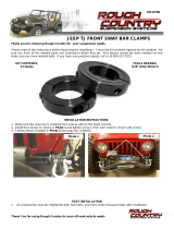
2. Working from the driver’s side, use a small center punch
and a hammer and carefully lift the factory crimped section
of the axle shaft nut from the axle shaft. Remove the axle
shaft nut and save. SEE PHOTOS BELOW
3. Remove the two 10mm bolts that attach the brake line to the
spindle and the upper control arm and save the hardware.
Remove the brake caliper and hang on the frame. DO NOT
LET THE CALIPER HANG BY THE BRAKE HOSE.
Remove the rotor and hub assembly and save. Remove the
brake rotor shield from the spindle and save with the
hardware. SEE PHOTOS IN NEXT COLUMN
Factory
crimped section

4. Remove the cotter pins in the outer tie rod end and the upper
and lower ball joints and discard. Use a ball joint fork and
separate the ball joints and tie rod from the knuckle. Remove
and save the knuckle, discard the hardware. SEE PHOTO
BELOW
5. Remove the shock assembly and discard, save the hardware.
Remove the lower control arm and discard, save the
hardware. SEE PHOTO BELOW
6. Remove the banjo bolt and brake hose from the caliper. Re-
route the brake hose back through the upper a-arm and re-
connect the hose to the caliper. Re-tighten the banjo bolt.
SEE PHOTOS IN NEXT COLUMN

7. Remove the upper control arm and save the hardware. SEE
PHOTO ON NEXT PAGE
8. Remove the axle CV shaft from the front differential and
with a paint pen, mark on the inner and outer CV’s and axle
where they were removed from (drv front inner / drv. front
outer). The CV’s and axle shafts are front and rear / inner
and outer specific. They MUST go back into the proper
locations. SEE PHOTO BELOW
9. Repeat steps two through eight on the passenger side
10. If you are installing the optional weld on gusset kit, do so at
this time.
11. Locate the passenger front CV axle. Carefully cut the
factory boot clamps from the CV boots (DO NOT CUT
THE CV BOOT. THEY WILL BE RE-INSTALLED).
Starting with the inner CV, slide the boot down the axle to
access the inside of the CV. First remove the large snap ring
right at the base of the CV and pull the CV housing from the
assembly. Using a snap ring tool, remove the small snap ring
from the end of the CV shaft. Carefully remove the CV cage
from the axle shaft making sure not to loose any of the CV
balls. Remove both of the CV boots and save with all of the
clips and internal parts, discard the old CV boot clamps.
SEE PHOTOS IN NEXT COLUMN AND PAGE
Do not damage
CV boot

Large snap ring
(one-wire style)
12. Place the CV axle into a vise with aluminum or soft jaws.
Use a soft brass or rubber mallet and carefully strike the
outer CV downward to disengage the inner snap ring which
holds the CV onto the axle. USE CARE NOT TO
DAMAGE THE CV OR CV HOUSING. SEE PHOTOS
IN NEXT COLUMN

13. Locate FT95074 Front Long travel Axle, FT95060 Clamp
Kit with Snap Rings, and the factory outer CV and Boot.
Open the clamp and snap ring kit and the factory snap rings
which were just removed. Match the old snap rings to the
new ones in the kit (provided FT95060 kit has snap rings for
all EIGHT CV’s). Place the CV boot onto the axle and
follow with the small snap ring (one wire style) onto the
large splined end of new long travel axle. Place the outer CV
into a vise and LIGHTLY tighten enough just to hold the
CV. With the boot and C-Clip installed, insert the axle into
the CV to where the clip makes contact with the CV. Use a
soft brass or rubber mallet and carefully strike the axle
downward to engage the inner snap ring into the CV. Slide
boot down over the CV. SEE PHOTOS & DIAGRAM ON
NEXT PAGE & LAST PAGE OF INSTRUCTIONS

14. Locate the Factory inner CV and internal parts, CV Boot,
and new supplied snap ring. Install the CV boot onto the
axle followed by the CV Cage (tapered end on first). If
necessary, use a soft brass or rubber mallet and carefully
strike the CV cage downward to access the snap ring groove
on the axle shaft. Using snap ring pliers, install the snap ring
onto the end of the axle shaft. SEE PHOTOS ON NEXT
PAGE
Tapered side of
CV Cage

15. Locate the Inner CV housing and factory large snap ring
(one wire style). Install the housing onto the axle over the
CV cage and install the large snap ring. Slide the CV boot
over the CV and Housing. SEE PHOTOS BELOW AND
ON NEXT PAGE
16. Locate two large and two small CV boot clamps from the
FT95060 clamp kit. Position the large clamp around the boot
and axle. Pull the clamp tight around the boot and mark the
clamp where it overlaps at the crimp lock with a paint pen.
Remove the clamp from the boot and cut the excess from the
strap. Repeat this step for the other three clamps on this axle.
SEE PHOTOS BELOW
17. Using a CV boot band clamp tool, clamp only the inner boot
clamps. Locate one of the supplied CV boot grease bags ( 4
bags are provided with this kit, one for each axle, half a
bag for each CV). Carefully pull back the boot from the
inner CV and insert HALF of the bag into one inner CV
boot. Re-install the boot onto the CV and use the clamp tool
and tighten the clamp. Repeat this step for the outer CV.
SEE PHOTO BELOW
Mark & cut at
the crimp lock

18. Repeat steps eleven through seven-teen for the driver side
CV axle.
19. Working from the passenger side, locate the assembled front
Long Travel axle and install into the front differential. Use a
large rubber mallet and tap the outer end of the axle shaft.
SEE PHOTO BELOW
20. Locate FT95002GR (driver upper), FT95003GR (driver
lower), FT95004GR (pass. upper), and FT95005GR (pass.
lower) control arms, FT95000 bushings, FT95004 sleeves,
and the supplied bushing lube. Place a small amount of lube
into each of the barrels on the arms. Using a press, press a
bushing into both ends of each barrel. Place more of the lube
onto the sleeves and use the press to install one into each set
of bushings.
21. Install the passenger lower a-arm into the factory a-arm
mounts and attach with the factory a-arm hardware (use
supplied thread-locking compound). Leave loose. SEE
PHOTO BELOW
22. Install the passenger upper a-arm with pre-installed ¾” heim
and jam nut into the factory a-arm mounts and attach with
the factory a-arm hardware. (use supplied thread-locking
compound) Leave loose. SEE PHOTO BELOW
IF YOU ARE INSTLLING THE HEAVY DUTY
STEERING KIT, DO SO NOW FOLLOWING THE
INSTRUCTIONS PROVIDED WITH THAT KIT AND
SKIP STEP 23 IN THIS INSTRUCTION SHEET
23. Remove the outer tie rod end and leave the factory jam nut
on the inner tie rod end. Locate FT95015 Tie Rod
Extension, FT95203 ½” Male Heim, and supplied ½” jam
nut. Thread the supplied ½” jam nut onto the ½” heim and
insert into the tie rod extension. Thread on the tie rod
extension (end with two reliefs cut into end of extension)
onto the inner tie rod to the factory jam nut. Adjust the tie
rod extension so there is an equal amount of thread on the
½” heim and the factory inner tie rod end (approx. ½”
above the jamb nut). SEE PHOTOS IN NEXT COLUMN,
NEXT AND LAST PAGE

24. Locate the factory knuckle. Remove the C-clip retainer and
then use a ball joint press and press out the lower ball joint
from the knuckle. Discard the ball joint and the C-clip. SEE
PHOTOS BELOW

25. Place the knuckle into the vise with aluminum or soft jaws
and use care not do damage. Use a drill with a ¾” drill bit
and drill out the knuckle at the upper ball joint location and
at the tie rod location. SEE PHOTOS BELOW
26. Locate FT95010 Upper Ball Joint Hat, FT95019 “top”
Lower Ball Joint Hat, FT95079 “bottom” Lower Ball Joint
Hat, and FT95021 Steering Arm Hat. Insert the upper ball
joint hat up into the previously drilled upper ball joint
location. Insert the lower ball joint hats into the lower ball
joint location (FT95019 in the top of the knuckle and
FT95079 in the bottom of the knuckle) and the FT95021
steering arm hat into the previously drilled tie rod location.
(use a rubber mallet only if necessary). SEE PHOTOS AND
DIAGRAMS ON NEXT PAGE AND LAST PAGE
FT95010 Upper
Ball Joint Hat
27. Install the knuckle assembly onto the CV shaft. Insert the
supplied FT95027 7/8” mis-alignment up into the bottom of
the uni-ball in the lower control arm and the FT95079 Mis-
alignment down into the top of the uni-ball. Then attach the
knuckle to the lower control arm with the supplied 9/16” x 3
½” hardware. Insert the FT95066 mis-alignments in the
heim joint in the upper control arm and then attach the
knuckle to the upper control arm using the supplied 9/16” x
3” hardware with a flat washer between the mis-alignment
and the knuckle. The ¾” heim and jam nut are set at just a
starting point, final adjustment can be made during the toe
set if necessary. (use supplied thread-locking compound)
Leave loose.
Upper ball joint
location
Outer Tie Rod
location
FT95021
Steering Arm
Hat

Upper and Lower Control Arm @ Knuckle
28. Locate FT95020 ½” Short Mis-alignment and the supplied
3/8” x 3 ¼” hardware. Insert the mis-alignment into the top
of the ½” heim in the new extended steering shaft followed
by the 3/8” bolt. Position the ½” heim and hardware onto the
FT95021 steering arm hat and through the knuckle. Place
one of the supplied 3/8” SAE Flat Washers and one of the
3/8” USS Flat Washers on the bottom of the knuckle along
with the 3/8 C-lock nut. Torque upper and lower control arm
bolts to 32 lbs, the 9/16” hardware to 95 lbs, and the 3/8”
hardware to 35 lbs (use supplied thread-locking compound).
Tighten the jam nut on the pre-installed ¾” heim on
the upper control arm
. SEE DIAGRAM ON NEXT
PAGE AND LAST PAGE
New Tie Rod Assembly @ Knuckle
FT95020
½”short mis-
ali
g
nment

29. Locate and install the factory hub assembly onto the knuckle
and axle shaft. Install the factory axle shaft nut and torque to
190 lbs. Use a center punch and re-crimp the hub nut in the
key way of the axle. SEE PHOTO BELOW
30. Locate the 10mm brake caliper bolts and re-attach the rotor.
Torque to 35 lbs. (use supplied thread-locking compound)
Locate the two of the supplied adel clamps and ¼”
hardware. Position the adel clamps over the brake hose and
attach to the tabs on the upper control arms. Torque to 10
lbs. SEE PHOTOS BELOW
1 – 3/8” USS
Flat Washer
1 - 3/8” SAE
Flat Washer

31. Locate FTR60138 Front Shock, provided shock mis-
alignments, and the factory shock hardware. Insert the mis-
alignments into the top of the shock and mount into the
stock upper mount with the factory hardware. Insert the mis-
alignments into the heim on the bottom of the shock. Mount
the bottom of the shock to the upper control arm mounts
with the SUPPLIED 10mm x 1.50 x 60mm bolts and
hardware. (use supplied thread-locking compound) Torque
to 32 LBS. SEE PHOTOS BELOW AND ON NEXT
PAGE. SEE DIAGRAM ON LAST PAGE FOR PROPER
MIS-ALIGNMENT LOCATIONS
32. Locate FT83179 Front Resi Mount Bracket and FT86013
Hardware kit that is provided with the front shocks. NOTE:
some 2005 & 2006 model rhinos have a factory locating
hole. If your Rhino has this locating hole on the front of the
frame section just above where the front upper control arm
mounts to the frame, use a drill with a 5/16” drill bit and
drill out to 5/16”. Locate the supplied 5/16” hardware and
attach the mount to the front of the frame and use a paint
pen or center punch to mark the second hole. Remove the
mount and drill the second hole in to the frame. Re-install
the bracket to the front of the frame and attach with the
supplied 5/16” hardware. If your Rhino DOES NOT have
the factory locating hole, position the mount onto the front
of the frame section just above where the front upper control
arm mounts to the frame. With the mount on the front of the
frame, hold the new bracket 3” from the top of the frame
section. Use a paint pen or center punch to mark the two
holes onto the back of the frame. Use a drill with a 5/16”
drill bit and drill out these two holes. Re-install the bracket
to the front of the frame section and attach with the supplied
5/16” hardware. Torque to 20 lbs. SEE PHOTOS IN NEXT
COLUMN
Use new provided
10mm x 60mm
hardware

Photo of passenger front
On Rhino’s without locating hole, measure 3” from top of frame section
33. Locate FT89028 Hose Clamps and position the shock
reservoir onto the new mount (as shown in photos) and
attach with the new clamps. Position the reservoir so the
hose does not make contact with the bottom side of the
hood. (rotate / twist the reservoir in the mount) Do not over
tighten the clamps or kink the reservoir hose. SEE PHOTOS
BELOW

34. Repeat steps nine-teen through thirty-three on the passenger
side.
35. Check the fluid level in the brake reservoir and add as
necessary. Bleed the brake system as per the manufacture’s
specification. See owners manual
36. Install tires and wheels and torque lug nuts to wheel
manufacturer’s specifications. Turn front tires left to right
and check for appropriate tire clearance.
REAR INSTRUCTIONS
37. With the Rhino on level ground, jack up the rear end of the
Rhino and support the frame rails with jack stands. Chock
the front tires. NEVER WORK UNDER AN
UNSUPPORTED VEHICLE! Remove the rear tires.
38. Rhino’s equipped with the rear inner wheel well lip must be
trimmed and flattened for maximum tire clearance during
rear suspension travel. Tilt the rear bed and use a paint pen
and mark the front, center, and rear of the inner wheel well
lip. SEE PHOTO BELOW
Bedside removed for photo only
39. Use a die grinder with a cut off wheel and cut the lip just
flush with the wheel well at the three marked spots. Once
the lip has been cut, use a hammer and flatten the lip
upwards until it is flush with the wheel well. Use a die
grinder with a sanding disc and sand down / round out the
front and rear lip where it was cut. Paint any bare metal
areas after all cutting and sanding is done. SEE PHOTOS
ON NEXT PAGE
Center Front Rear

40. Next, the flared portion of the rear wheel well needs to be
trimmed for adequate tire clearance during rear suspension
travel. Apply masking tape to the lower 4” of the entire
flared portion of the fender. Starting from the rear, mark a
1 ½” line above the lower edge. At the front of the wheel
well, the distance needs to be gradually reduced starting at
the radius to meet the existing front corner. SEE PHOTOS
BELOW
Sand edges
Apprx. 4 ½”
Rear of Rhino
Driver rear fender shown removed for photo only
41. Using an air saw, carefully cut the fender following the
mark. Follow with a die grinder with a sanding disc to
smooth out any rough edges or other imperfections.
42. Working from the driver’s side, use a small center punch
and a hammer and carefully lift the factory crimped section
of the axle shaft nut from the axle shaft. Remove the axle
shaft nut and the hub assembly and save. SEE PHOTOS IN
NEXT COLUMN
1 ½” cut
/