Page is loading ...

Installation Guide
PS12-180W-3-A
Power Supply
1 1 2 3
4 5
2 3
4
5
Components:
1. General LED PS12-180W-3-A Power Supply
2. Minimum 18 AWG (0.82mm) Wire - (UL Approved)
*Under certian conditions, a heavier guage wire may be neccesary.
3. PLTC Cable - UL Listed
4. 22 - 14 ASG (0.33 - 2.08mm) wire connectors or 22 - 18 AWG
(0.33 - 0.82mm) wire nuts, IDC connectors or butt splice
connectors, cable ties - UL Approved
5. #6 or #8 (M3 or M4) screws
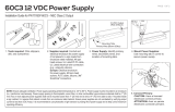
1. AC Input wires: Black = Line
White = Neutral, Green = Ground
DC Output wires:
Black = Negative (-),
Red = Positive (+)
2. For mounting purposes, several
mounting tabs have been placed
on the power supply end caps to
allow for flexibility in mounting
locations and positions.
Tools:
1. Wire Stippers
2. Screw Driver
3. Adjustable Wrench
4. Tape Measure
5. Drill
AC INPUT (3*AWG #18)
DC OUTPUT (2*AWG #18)
Mounting Tabs Mounting Tabs
3. Connect the power supply to the
product as outlined in the
SignRayz
®
/ SignRayz
®
PRO
Series Installation Guide.
Notes:
• Intended to be installed in another device, system or end product,
subject to Conditions of Acceptability of the UL SAM Manual.
• UL 48 Standard requires that the spacing between transformers,
ballasts, neon power supplies and LED power supplies shall be at
least 1 inch (25.4 mm) from end to end and 4 inches (101.6 mm)
from side to side.
• When connecting power supply to 277 VAC, make sure the input
voltage is correct and not 480 VAC.
• Use the proper gauge wire for connecting power supply to product.
• Do not overload the power supply. If the power supply is overloaded,
cycle input power to restart power supply.
• The grounding and bonding of the LED Driver must be done in
accordance with ordnance National Electric Code (NEC) Article 600.
• Follow all National Electric Codes (NEC) and local codes.
Wire Gauge (AWG)
18
16
14
12
10
STANDARD (ft)
18
29
45
71
120
METRIC (m)
5.5
8.8
13.7
21.6
36.6
*Distance from power supply to first LED module of the string
(at full capacity)
MAXIMUM DISTANCE*
Jumper Wire Gauge Chart
WARNING
RISK OF ELECTRICAL SHOCK
Turn OFF power before
perfoming any maintenance.
General LED Power Supply
• The maximum case temperature shall not exceed 75ºC (167°F) when used in end product.
• These products are intended to be connected to a max. 20 A branch circuit.
• These products are intended for use in dry, damp and wet locations.
AgiLight, Inc., a Division of General LED Opco, LLC. +1.866.482.0203
1074 Arion Cirlce, Suite 116, San Antonio, TX 78216
© 2017 General LED Opco, LLC. 2017 All rights reserved.
Product Specifications subject to change without notice. 10-2017
www.AgiLight.com

Installation Guide
PS12-180W-3-A
Power Supply
WARNING
RISK OF ELECTRICAL SHOCK
Turn OFF power before
perfoming any maintenance.
Power Supply Load Chart
Product
BASE G2B
CORE G2B
APEX G2B
CORE G3B
APEX G3B
MINI
3MIN
COLOR Ruby Red
COLOR True Red
COLOR Orange
COLOR Yellow
COLOR Green
COLOR Blue
PRO115 2L1
PRO115 2G3
PRO160 1G3A
PRO160 2B1C
PRO215 2G3C
PRO260 1G3B
PRO260 2G3B
PRO260 2B1C
PRO260 2L3B
PRO MINI 3L1
PRO MINI 2B6
PRO COLOR Red
PRO COLOR Yellow
PRO COLOR Green
PRO COLOR Blue
Ultra MINI 50A
Ultra MINI 35A
Ultra MINI 50A Red
Ultra MINI 50A Green
Ultr
a MINI 50A Blue
Ultra MINI 35A Red
Ultra MINI 35A Green
Ultra MINI 35A Blue
Maximum
Single String
126
126
48
70
50
120
120
95
95
90
90
95
95
102
115
70
70
52
44
44
44
44
120
128
100
80
100
100
150
180
200
200
200
245
245
245
Per Channel
Modules
126
126
48
70
50
162
162
120
120
90
90
131
120
102
115
70
70
52
44
44
44
44
162
128
112
92
112
112
230
230
460
460
460
460
460
460
General LED Power Supply
• The maximum case temperature shall not exceed 75ºC (167°F) when used in end product.
• These products are intended to be connected to a max. 20 A branch circuit.
• These products are intended for use in dry, damp and wet locations.
AgiLight, Inc., a Division of General LED Opco, LLC. +1.866.482.0203
1074 Arion Cirlce, Suite 116, San Antonio, TX 78216
© 2017 General LED Opco, LLC. 2017 All rights reserved.
Product Specifications subject to change without notice. 10-2017
www.AgiLight.com
/


