15
2. Web Configuration Interface
The following table describes the columns found in the My Targets section Data Pane.
Server Name
The Server Name column displays all of the Target Servers and Serial devices that are accessible to the logged in
account. The Server Name for each port can be changed in the Configuration section of the Web Configuration
Interface (see section 2.4.6 Switch Configuration for details). Double-click on a Target Server to initiate a remote
session (See section 3. Conducting a Remote Session for details on managing a remote session).
Server Status
The Server Status column shows the status of the Target Server connected to the corresponding port: Available, Off,
Blocked, Local Exclusive Session, Remote Exclusive Session, Remote Session, or No Communications with Device.
• Available – Indicates that a computer is connected to the corresponding port, and is available for use. This server
status is indicated by a Blue port in the graphic of the KVM’s back panel.
• Off – Indicates that a computer/server is not connected to the corresponding port. This server status is indicated by
a Black port in the graphic of the KVM’s back panel.
• Blocked – Indicates that the maximum number of simultaneous users have logged onto the KVM and are accessing
connected computers. In this situation, the status of all Target Servers is Blocked, except those that are being
accessed by other accounts. For those ports that are being accessed by other accounts, the status will appear as
either Remote Session or Remote Exclusive Session. (see sections 3.3 Shared Session and 3.4 Exclusive Session
for details) Target Servers that are Blocked cannot be accessed. A Blocked server status is indicated by a Reddish
Brown port in the graphic of the KVM’s back panel.
• Local Exclusive Session – Indicates that the corresponding port is currently being accessed by a local account.
This server status is indicated by a Green port in the graphic of the KVM’s back panel.
• Remote Exclusive Session – Indicates that an account is currently accessing the corresponding port in exclusive
mode, preventing anyone else from connecting to it. This server status is indicated by an Orange port in the graphic
of the KVM’s back panel.
• Remote Session – Indicates that an account is currently accessing the corresponding port in share mode, which allows
up to 5 users to access a port at the same time. (see sections 3.3 Shared Session and 3.4 Exclusive Session for
details) This server status is indicated by a Green port in the graphic of the KVM’s back panel.
• No Communications with Device – Indicates that a computer/server is connected to the corresponding port, but
is not communicating with the KVM and is therefore inaccessible. This server status is indicated by a Red port in the
graphic of the KVM’s back panel.
User
The User column displays the account that is currently accessing the corresponding port.
There is an untitled column to the right of the User column. This column will contain a colored icon that indicates which
type of SIU is connected. Green indicates that a B078-101-USB2 is connected; Light Blue indicates that a B078-101-
USB-1 is connected; Orange indicates that a 0SU51078, 0SU51079, B078-101-PS2, or B078-101-USB is connected.
SIU (Server
Interface Unit)
This column includes a description of the connected SIU. The B078-101-USB2 is described as a FVM SIU, the B078-
101-USB-1 as a VM SIU, and the 0SU51078, 0SU51079, B078-101-PS2, and B078-101-USB as a SIU.
The following table describes the functionality of the Web configuration toolbar buttons.
Icon Description
Click the Save icon after making any changes in the Configuration section. This saves your changes.
In the Configuration section, clicking the Reload icon will return a page to the most recently saved settings. For example,
if you enter incorrect information into a field and want to go back to the previous value, but can’t remember what the
previous value of the field was, clicking the Reload icon will bring it back.
Click the Device Reboot icon to reboot the KVM.
Click the Device Upgrade to perform a firmware upgrade on the KVM (See section 2.4.1 Firmware Upgrade for details).
Click the SIU Upgrade icon to perform a firmware upgrade on the SIUs in the installation (See section 2.4.1 Firmware
Upgrade for details).
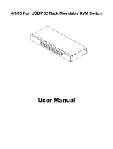
2.4 Configuration Section
The Configuration section of the Web Configuration Interface is
where administrator accounts can configure the KVM’s settings and
account access. When accessing the Configuration section, there
are a number of sub-sections displayed as notebook tabs. Clicking
on a tab will display the settings for that sub-section. The features of
the Configuration section are described in the following pages.