Page is loading ...

TV Information:
Use this space to record the model and serial numbers of
your television. This information is on the back of your TV.
Model number
Serial number
visit our website at
www.mitsubishi-tv.com
Owner’s Guide
Projection Television Models
WD-52525, WD-52725
WD-62525, WD-62725
TM
TM

The lightning flash with arrowhead symbol within an equilateral triangle is intended to alert the user of
the presence of uninsulated “dangerous voltage” within the product’s enclosure that may be sufficient
magnitude to constitute a risk of electric shock.
The exclamation point within an equilateral triangle is intended to alert the user to the presence of
important operating and maintenance (servicing) instructions in the literature accompanying the
appliance.
WARNING: TO REDUCE THE RISK OF FIRE OR ELECTRIC SHOCK, DO NOT EXPOSE THIS APPLIANCE TO RAIN
OR MOISTURE.
CAUTION: TO PREVENT ELECTRIC SHOCK, MATCH WIDE BLADE OF PLUG TO WIDE SLOT, FULLY INSERT.
NOTE TO CATV SYSTEM INSTALLER: THIS REMINDER IS PROVIDED TO CALL THE CATV SYSTEM INSTALLER’S
ATTENTION TO ARTICLE 820-40 OF THE NEC THAT PROVIDES GUIDELINES FOR THE PROPER GROUNDING AND,
IN PARTICULAR, SPECIFIES THAT THE CABLE GROUND SHALL BE CONNECTED TO THE GROUNDING SYSTEM
OF THE BUILDING, AS CLOSE TO THE POINT OF CABLE ENTRY AS PRACTICAL.
CAUTION
RISK OF ELECTRIC SHOCK
DO NOT OPEN
CAUTION: TO REDUCE THE RISK OF ELECTRIC SHOCK, DO NOT REMOVE COVER (OR
BACK). NO USER SERVICEABLE PARTS INSIDE. REFER SERVICING TO QUALIFIED SERVICE
PERSONNEL.
This TV is very heavy! Exercise extreme care when lifting or moving. A minimum of two adults
should lift or move the TV.
Portions of the advanced circuitry of this TV must continue to operate even when the TV is turned
off. Some of these circuits therefore need to be cooled at all times. A low power standby fan may
be heard in a quiet environment. This is normal operation.
Custom cabinet installation must allow for proper air circulation around the television.
STAND REQUIREMENT
CAUTION: Mitsubishi TV models WD-52525 and WD-52725 are for use only with Mitsubishi stand, model MB-52525.
Mitsubishi TV models WD-62525 and WD-62725 are for use only with Mitsubishi stand model MB-62525. Use with
other stands is capable of resulting in instability causing possible injury.

FCC Declaration of Conformity
Product: Projection Television Receiver
Models: WD-52525, WD-52725, WD-62525, WD-62725
Responsible Party: Mitsubishi Digital Electronics America, Inc.
9351 Jeronimo Road
Irvine, CA 92618-1904
Telephone: 949-465-6000
This device complies with Part 15 of the FCC Rules. Operation is subject to the following two conditions:
(1) This device may not cause harmful interference, and
(2) this device must accept any interference received, including interference that may cause undesired operation.
Note: This equipment has been tested and found to comply with the limits for a Class B digital device, pursuant to
part 15 of the FCC Rules. These limits are designed to provide reasonable protection against harmful interference
in a residential installation. This equipment generates, uses and can radiate radio frequency energy and, if not
installed and used in accordance with the instructions, may cause harmful interference to radio communications.
However, there is no guarantee that interference will not occur in a particular installation. If this equipment does
cause harmful interference to radio or television reception, which can be determined by turning the equipment off
and on, the user is encouraged to try to correct the interference by one or more of the following measures:
• Reorient or relocate the receiving antenna.
• Increase the separation between the equipment and the receiver.
• Connect the equipment into an outlet on a circuit different from that to which the receiver is connected.
• Consult the dealer or an experienced radio/TV technician for help.
Changes or modifications not expressly approved by Mitsubishi could cause harmful interference and would
void the user’s authority to operate this equipment.
CAUTION: To assure continued FCC compliance, the user must use a shielded video interface cable
with bonded ferrite cores at both ends, when using the PC or HDMI input.

Contents
Chapter 1 Television Overview
TV Accessories............................................................................................................. 10
Special Features........................................................................................................... 10
Front Control Panel ...................................................................................................... 11
Front Panel Inputs and Media Card Slots .................................................................... 12
Back Panel.................................................................................................................... 13
Chapter 2 Connecting
External Devices & NetCommand® Setup .................................................................. 16
Wall Outlet Cable or Cable Box.................................................................................... 17
CableCARD™ Technology ........................................................................................... 18
Single Lead Antenna .................................................................................................... 19
Separate UHF and VHF Antennas ............................................................................... 19
VCR Video and Audio to an Antenna or Wall Outlet Cable .......................................... 20
VCR Video and Audio to a Cable Box .......................................................................... 21
A/V Receiver or Stereo System.................................................................................... 22
Satellite Receiver or Other Device with S-Video .......................................................... 22
DVD Player with Component Video.............................................................................. 23
Computer with a PC Monitor Output............................................................................ 23
DTV Receiver
with Component Video.............................................................................................. 24
with RGB, HV Video ................................................................................................. 25
M-Link Control.............................................................................................................. 26
RS-232C Connection ................................................................................................... 26
HDMI Device................................................................................................................. 26
DVI Device .................................................................................................................... 26
IR Emitter NetCommand® ........................................................................................... 27
Compatible IEEE 1394 Devices .................................................................................... 28
Helpful Hints ................................................................................................................. 30
Chapter 3 NetCommand
®
Setup and Editing
Using the Remote Control with NetCommand®.......................................................... 32
Remote Control Functions: Overview........................................................................... 33
Remote Control Functions:
Operation................................................................................................................. 34
Care ......................................................................................................................... 34
Sleep Timer ............................................................................................................. 34
NetCommand® OnScreen Buttons ............................................................................. 35
3D Graphical Viewpoint® Menu System...................................................................... 36
NetCommand® Initial Setup ........................................................................................37
Edit NetCommand®
Add an A/V Receiver .............................................................................................. 39
Add Devices ........................................................................................................... 42
Change Devices ..................................................................................................... 46
Delete Devices........................................................................................................ 46
Finish Screen.......................................................................................................... 46

Chapter 4 IEEE 1394 Devices and NetCommand® Controlled Recordings
IEEE 1394 Devices and NetCommand® Control ......................................................... 48
Adding IEEE 1394 Devices Automatically..................................................................... 49
Device Selection Menu................................................................................................. 51
Using the DEVICE MENU Button to Display Menus........................................................ 52
Using the Guide Button to Display ChannelView™ and Menus................................... 53
NetCommand® Controlled Recordings....................................................................... 54
NetCommand® and Traditional VCR’s......................................................................... 54
NetCommand® Controlled Peer-to-Peer Connections ............................................... 56
Direct VCR Recording from an Antenna or Cable Screen ........................................... 57
A/V Disc Search ........................................................................................................... 57
Track List Screen ......................................................................................................... 57
PC Viewing ................................................................................................................... 58
MediaCommand™ and Media Card Playback............................................................. 59
Chapter 5 TV Menu Screen Operations
Main Menu Choices...................................................................................................... 62
Setup Menu .................................................................................................................. 63
NetCommand® Menu .................................................................................................. 64
Antenna Menu .............................................................................................................. 65
Time Menu.................................................................................................................... 67
Captions Menu ............................................................................................................. 68
V-Chip Lock Menu........................................................................................................ 70
AudioVideo Menu ......................................................................................................... 73
A/V Settings Descriptions ............................................................................................ 74
Operation of PIP and POP............................................................................................ 76
Chapter 6 Special Features
Display Formats ........................................................................................................... 78
Device Control with NetCommand®............................................................................ 81
Appendix A: Bypassing the V-Chip Lock ..................................................................... 83
Appendix B: Specifications .......................................................................................... 85
Appendix C: Remote Control Programming Codes..................................................... 87
Appendix D: On-Screen Information Displays ............................................................. 90
Appendix E: NetCommand® Specialized Device Keys .............................................. 91
Appendix F: Cleaning and Service ............................................................................... 92
Appendix G: Diamond Shield™ Removal .................................................................... 93
Appendix H: Filter Cleaning.......................................................................................... 94
Lamp Replacement ...................................................................................................... 95
Troubleshooting............................................................................................................ 97
Additional Information .................................................................................................. 102
Index............................................................................................................................. 103
Warranty ....................................................................................................................... 105

6
7
IMPORTANT SAFEGUARDS
Please read the following safeguards for your TV and retain for future reference. Always follow all
warnings and instructions marked on the television.
1. Read, Retain and Follow All Instructions
Read all safety and operating instructions before operating the TV. Retain the safety and operating instructions
for future reference. Follow all operating and use instructions.
2. Heed Warnings
Adhere to all warnings on the appliance and in the operating instructions.
3. Cleaning
Unplug the TV from the wall outlet before cleaning. Do not use liquid, abrasive or aerosol cleaners. Cleaners can
permanently damage the cabinet and screen. Use a lightly dampened cloth for cleaning.
4. Attachments and Equipment
Never add any attachments and/or equipment without approval of the manufacturer as such additions may result
in the risk of fire, electric shock or other personal injury.
5. Water and Moisture
Do not use the TV where contact with or immersion in water is possible. Do not use near bath tubs, wash bowls,
kitchen sinks, laundry tubs, swimming pools, etc.
6. Accessories
Do not place the TV on an unstable cart, stand, tripod, or table. The TV may fall, causing seri-
ous injury to a child or adult and serious damage to the TV. Use only with a cart, stand, tripod,
bracket or table recommended by the manufacturer, or sold with the TV. Any mounting of
the TV should follow the manufacturer’s instructions, and should use mounting accessories
recommended by the manufacturer.
An appliance and cart combination should be moved with care. Quick stops, excessive force,
and uneven surfaces may cause the appliance and cart combination to overturn.
7. Ventilation
Slots and openings in the cabinet are provided for ventilation and to ensure reliable operation of the TV and to
protect it from overheating. Do not block these openings or allow them to be obstructed by placing the TV on a
bed, sofa, rug, or other similar surface. Nor should it be placed over a radiator or heat register. If the TV is to be
placed in a rack or bookcase, ensure that there is adequate ventilation and that the manufacturer’s instructions
have been adhered to.
8. Power Source
This TV should be operated only from the type of power source indicated on the marking label. If you are not sure
of the type of power supplied to your home, consult your appliance dealer or local power company.
9. Grounding or Polarization
This TV is equipped with a polarized alternating current line plug having one blade wider than the other. This plug
will fit into the power outlet only one way. If you are unable to insert the plug fully into the outlet, try reversing the
plug. If the plug should still fail to fit, contact your electrician to replace your obsolete outlet. Do not defeat the
safety purpose of the polarized plug.
10. Power-Cord Protection
Power-supply cords should be routed so that they are not likely to be walked on or pinched by items placed
upon or against them, paying particular attention to cords at plugs, convenience receptacles, and the point
where they exit from the TV.
11. Lightning
For added protection for this TV during a lightning storm, or when it is left unattended and unused for long
period of time, unplug it from the wall outlet and disconnect the antenna or cable system. This will prevent
damage to the TV due to lightning and power-line surges.

6
7
IMPORTANT SAFEGUARDS, continued
12. Power Lines
An outside antenna system should not be located in the vicinity of overhead power lines or other electric light or
power circuits, or where it can fall into such power lines or circuits. When installing an outside antenna system,
extreme care should be taken to keep from touching such power lines or circuits as contact with them might be
fatal.
13. Overloading
Do not overload wall outlets and extension cords as this can result in a risk of fire or electric shock.
14. Object and Liquid Entry
Never push objects of any kind into this TV through openings as they may touch dangerous voltage points or short-
out parts that could result in fire or electric shock. Never spill liquid of any kind on or into the TV.
15. Outdoor Antenna Grounding
If an outside antenna or cable system is connected to the TV, be
sure the antenna or cable system is grounded so as to provide some
protection against voltage surges and built-up static charges.
Article 810 of the National Electric Code, ANSI/NFPA No. 70-2002,
provides information with respect to proper grounding of the mast
and supporting structure, grounding of the lead in wire to an antenna
discharge unit, size of grounding conductors, location of antenna
discharge unit, connection to grounding electrodes, and requirements
for the grounding electrode.
16. Servicing
Do not attempt to service this TV yourself as opening or removing covers may expose you to dangerous voltage
or other hazards. Refer all servicing to qualified service personnel.
17. Damage Requiring Service
Unplug the TV from the wall outlet and refer servicing to qualified service personnel under the following
conditions:
(a) When the power-supply cord or plug is damaged.
(b) If liquid has been spilled, or objects have fallen into the TV.
(c) If the TV has been exposed to rain or water.
(d) If the TV does not operate normally by following the operating instructions, adjust only those controls that are
covered by the operating instructions as an improper adjustment of other controls may result in damage and
will often require extensive work by a qualified technician to restore the TV to its normal operation.
(e) If the TV has been dropped or the cabinet has been damaged.
(f) When the TV exhibits a distinct change in performance - this indicates a need for service.
18. Replacement Parts
When replacement parts are required, be sure the service technician has used replacement parts specified by the
manufacturer or have the same characteristics as the original part. Unauthorized substitutions may result in fire,
electric shock or other hazards.
19. Safety Check
Upon completion of any service or repair to the TV, ask the service technician to perform safety checks to
determine that the TV is in safe operating condition.
20. Heat
The product should be situated away from heat sources such as radiators, heat registers, stoves or other products
(including amplifiers) that produce heat.

8
Chapter . . .
Our Thanks...
Thank you for choosing Mitsubishi as your premier Home Entertainment provider.
This Owner’s Guide describes the features and functions of your Mitsubishi
widescreen, high definition TV. We urge you to examine this Owner’s Guide to
become familiar with the innovative features and operations this unique television
offers.
The very core of our corporate philosophy is to provide our customers with the
very best. Our development team at Mitsubishi has worked to provide you with
a television that defines “state-of-the-art,” with the capability to meet your needs
now and in the future.
Whether this is your first Mitsubishi electronic product, or an addition to your
Mitsubishi collection, we believe you and your family will continue to enjoy your
Mitsubishi home theater for many years.
Thank you,
Mitsubishi Digital Electronics America, Inc.

8
Chapter . . .
1
Television Overview
TV Accessories ..........................................................................10
Special Features ........................................................................10
Front Control Panel.................................................................... 11
Front Panel Inputs and Media Card Slots ...............................12
Back Panel .................................................................................13

10
11
TV Accessories
Please take a moment to review the following
list of items to ensure that you have received
everything including:
Special Features
Your new High Definition widescreen television has
many special features that make it the perfect center
of your home entertainment system, including:
High Definition DLP™ Display System
Your widescreen Mitsubishi HDTV uses Texas
Instruments Digital Light Processing™ technology.
This TV is truly a high performance multimedia monitor
uniquely capable of both stunning high definition video
images and clear detailed high resolution PC images.
Your TV is able to accept video signals in the standard
video scanning rates of 480i, 480p, 720p and 1080i. It
is also able to accept signals with PC resolutions from
VGA (640 x 480) through XGA (1024 x 768). When using
a compatible graphics card and controlling software,
this TV is also able to accept the custom PC resolution
of 720p (1280 x 720). All signals will be converted to
720p for final display.
Digital Cable Ready (CableCARD™)
Your widescreen Mitsubishi HDTV is “Plug-and-
Play” ready. It can descramble a cable provider’s
one-way digital signals with the use of a CableCARD
security module. The CableCARD is used in place
of a traditional cable box to access digital cable
programming (including high definition). Contact your
local cable provider for availability information and
service details.
NetCommand
®
Home Network
Control System
Your widescreen Mitsubishi HDTV offers a new level
of networking to combine selected older products
with new and future digital products. NetCommand
supports IEEE 1394 connections, Audio Video Control
system (AV/C), 5C copy protection and IR control of
selected older products such as VCRs, DVD players,
cable boxes or satellite receivers. NetCommand
includes the ability to learn remote control signals
directly from many devices, allowing you to customize
the NetCommand system in a way that works best for
your viewing.
16:9 Widescreen Picture Format
Enjoy a full theatrical experience in the comfort of your
home. View pictures as film directors intended them.
Digital TV broadcasts, DVDs and newer video game
consoles support this widescreen format.
Media Cards
You can display a slideshow of your favorite JPEG
pictures or listen to MP3 or WMA audio selections that
have been recorded on compatible media cards.
POWER
PAUSE
REC
3
6
9
QV
DEVICE
MENU
HOME
1
7
SQV
4
SUB/CANCEL
2
5
8
0
TV MENU
GUIDE
MUTE
DEVICE
CH
VOL
REW/REV
FF/FWD
PLAY
STOP
SLEEP
INFO
V-CHIP
AUDIO
VIDEO
CONNECT
TV
AUDIO
CABLE/DBS/DTV
DVD
VCR
FORMAT
PIP CH
PIP/POP
EXCH
PIPDEVICE
��
��
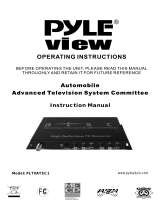
1. Remote Control
2. Two AA Batteries
6. Product Registration Card (not pictured)
7. Owner’s Guide (not pictured)
8. Quick Reference Card (not pictured)
4. One Quadruple IR Emitter Cable (allows NetCommand to
control other devices)
3. One Digital Audio Cable (sends the audio of digital
channels to a digital audio video receiver).
5. One Double IR Emitter Cable (allows NetCommand to
control other devices)

10
11
Front Control Panel
The buttons on the Front Control Panel highlighted in gray are duplicated on the remote control. The top row of
labels show the control functions when there are no TV menus displayed on the screen. The bottom row of labels
show the control functions when the TV menus are displayed on the screen or when a special function has been
activated. See Remote Control Overview, for further details on the functions of these buttons.
System Reset
If the TV will not respond to either the remote control or the front panel controls and/or will not power Off, press the
SYSTEM RESET button with a pointed item like the end point of a paperclip. The TV will turn Off and the TIMER
light will flash quickly for about one minute. When the TIMER light stops flashing, you may again turn on the TV. The
changes you made the last time the TV was on before you used the SYSTEM RESET button may be lost, however,
the changes that were previously saved are not lost.
Indicators
Please refer to the table below for conditions when the indicator lights will display.
COLOR LAMP LIGHT
INDICATOR
TIMER/
POWER
COLOR STATUS LIGHT INDICATOR
None (off) Power off Power off None (off) Power off
Green
(steady light)
n/a Power on Green
(steady light)
n/a
Green
( fast blinking light)
n/a Starting
up*
Green
( fast blinking light)
n/a
Green
(blinking light)
Power just turned off,
TV cooling down (1
minute). Cannot turn
the TV back on until
blinking stops.
TV Timer
is set
Green
(blinking light)
n/a
Yellow
(steady light)
Lamp life end warning.
A new lamp should be
purchased.
See Appendix H.
n/a Yellow
(steady light)
Operating temperature is too high.
The dust filter may be dirty. See
Appendix H.
or
The room temperature too hot. Turn off
TV until the room is cooler.
Yellow
(blinking light)
Lamp cover door is
open
or no lamp installed.
See Appendix H.
n/a Yellow
(blinking light)
The filter cover is open or not secure.
See Appendix H.
Red
(steady light)
Lamp has failed,
replacement is
required.
See Appendix H.
n/a Red
(steady light)
Service required.
Turn off TV and call your dealer or a
Mitsubishi Authorized Service Center.
See www.mitsubishi.com or call 1-800-
332-2119.
Red
(blinking light)
n/a n/a Red
(blinking light)
Service required.
Turn off TV and call your dealer or a
Mitsubishi Authorized Service Center.
See www.mitsubishi.com or call 1-800-
332-2119.
*Each time the TV is plugged into a wall electrical outlet, when power is restored
after a power failure, or when using
the SYSTEM RESET button, this light will flash for about one (1) minute.
A/V Reset
There may be times when you wish to reset the A/V (Audio and Video) settings back to the factory defaults. To return
all of the settings at once, press GUIDE and FORMAT on the front panel at the same time. To reset the defaults for
individual devices, use the A/V Memory Reset selection on the AudioVideo menu.
<
DEVICEGUIDE
CANCEL
MENU
ENTER
MENUFORMAT
– CH –
<
>
ADJUST
– VOL –
<
>
>
< >
POWER
SYSTEM
RESET
LAMP STATUS TIMER

12
13
�
Input 3
This input can be used for
convenient connection of a
camcorder or other video
device to the TV. Please
note that if you connect
to the S-VIDEO terminal,
the VIDEO terminal is
deactivated. The VIDEO
terminal is active when there
is no S-Video connection.
Front Panel Inputs and Media Card Slots
INPUT 3
Media Card Slots and IEEE 1394
Input/Output
There are four card slots in the front of the TV that
allow the display of JPEG pictures from many digital
cameras, MP3 or WMA audio files recorded from
computers or other digital recording devices. The
card slots are designed for specific types of cards
and other cards or objects should not be inserted
into the slots as this may damage the TV. CARD-
1 slot is compatible with both MultiMediaCard™
(MMC) and Secure Digital (SD) cards. CARD-2 slot
is compatible with SmartMedia™ cards. CARD-3
slot is compatible with CompactFlash® cards and
CARD-4 is compatible with MEMORY STICK™ cards.
See media card (slideshow, playlist) Setup for details
about JPEG, MP3 and WMA file types that are
compatible with the TV.
The IEEE 1394 input/output allows for temporary
connection of IEEE 1394 devices such as some
camcorders, to the front of the TV. This connection
works the same way as rear IEEE 1394 connections,
please refer to the NetCommand® information
(Chapter 3) for details.
Portions of the advanced circuitry of this TV
must continue to operate even when the TV is
turned off. Some of these circuits therefore
need to be cooled at all times. A low
power standby fan may be heard in a quiet
environment. This is normal operation.
IMPORTANT

12
13
IR EMITTER
NetCommand
R
DVI
Analog Audio
INPUT-1
AUDIO 2
AUDIO/VIDEO 1
AUDIO
L(MONO)R
INPUT-2
COMPONENT-1
YPbPr (480i/480p/720p/1080i)
Y/G
Pb/BPr/R
COMPONENT-2
YPbPr (480i/480p/720p/1080i)
INPUT-DTV
YPbPr / RGB HV
(480i/480p/720p/1080i)
DTV/
CABLE/
VHF/
UHF
ANT-2
ANT-1
DIGITAL
AUDIO
PC
VGA/SVGA/XGA/
720p
60 Hz
PC-
AUDIO
PC-
INPUT
M-LINK
CONTROL/
RS-232C
HDMI
M-LINK
IEEE1394
INPUT/OUTPUT
L
R
VIDEO S-VIDEO
MONITOR
OUTPUT
L
R
V H
CARD
TOP
CableCARD SLOT
TM
1.
2.
3.
4.
5.
6.
7.
8.
9.
10.
11.
MAIN
AUX
12.
Back Panel
1. Antenna (ANT-1 MAIN, ANT-2 AUX)
ANT-1 MAIN and ANT-2 AUX can each receive both
digital and analog over-the-air channels from a VHF/UHF
antenna or non-scrambled digital/analog cable channels.
Your primary viewing signal source should be connected
to ANT-1 MAIN. ANT-1 MAIN must be used to view
premium subscription cable TV service authorized by the
CableCARD™ access card. The CableCARD access card
is provided by your local cable company. ANT-2 AUX can
continue to receive over-the-air or non-scrambled cable
signals.
2. CableCARD™ Slot
The CableCARD access card provided by your cable TV
service provider is inserted into this slot. The top of the
card should face in the direction the CARD TOP arrow
indicates.
CableCARD is a nationwide standard system that allows
your local cable TV provider to supply you with an
access card customized to your account. This card
allows the TV to receive, decode and unscramble the
premium digital channels included in your cable TV
subscription without the use of a cable box. See page
16 for additional CableCARD information and activation
instructions.
If your cable company is not currently offering
CableCARD access cards, you will need to use a cable
box provided and authorized by your local cable company
to view scrambled channels.
3. Input DTV (480i/480p/720p/1080i)
This input is used to connect an external DTV receiver,
and can be configured for YPbPr or RGB plus H&V signal
types. Please see Appendix B for signal compatibility.
4. Component-1, -2 Inputs
YPbPr (480i/480p/720p/1080i)
These inputs can be used for the connection of devices
with component video outputs, such as a DVD player,
external HDTV receiver or compatible video game system.
Please see Appendix B for signal compatibility.
5. Input-1, -2; Monitor Output
(Audio/Video 1, Audio 2)
Input 1 and 2 can be used for the connection of a VCR,
Super VHS (S-VHS) VCR, DVD player, standard satellite
receiver or other A/V device to the TV. Please note that
if S-VIDEO and VIDEO are available for the input, you
must choose to connect only one. They cannot both be
connected at the same time.
The Monitor Output sends the TV audio and video
signals from the antennas or Inputs to an A/V receiver
or other analog A/V equipment such as a VCR. Digital
channels and IEEE 1394 signals will be down converted
to analog signals compatible with traditional VCRs.
Digital channels or IEEE 1394 signals may be output with
copy protection or may display no video signals if they
have copy restrictions. There will be only audio and no
video signals from Monitor Outputs when viewing the
Component 1 & 2 inputs, INPUT-DTV, the HDMI input or
Cards 1-4.

14
Chapter . . .
Back Panel, continued
Monitor Output Audio/Video 1 should be connected to
a VCR for recording. Monitor Output Audio 2 should
be connected to your A/V receiver for home theater
surround sound.
6. PC Input and Audio
(VGA/WVGA/SVGA/WSVGA/XGA/
720p, 60Hz )
This input can be used for the connection of a computer.
Please see Appendix B for signal compatibility. If
NetCommand® has not been setup, the on-screen
display name will be VGA.
Stereo audio inputs are also provided for the PC
connection.
7. DTV Link/IEEE1394
These jacks allow the TV to connect to external IEEE
1394 digital products by means of a single cable. Three
jacks (one on the front panel and two on the back) are
provided for this purpose, which allow for a high degree
of flexibility for connecting your NetCommand controlled
system. Detailed information regarding IEEE 1394
connection requirements are in Chapter 4.
8. IR Emitter-NetCommand
®
Two jacks are provided for connecting IR emitters. IR
Emitters connected to these jacks are used by the
NetCommand system of the TV to control external analog
devices such as VCRs, DVDs, cable boxes, satellite
receivers and audio receivers.
9. DVI Analog Audio
Unlike HDMI, DVI does not carry audio information on
the same cable. Use these analog stereo audio inputs
when using the HDMI input with a device that outputs DVI
instead of HDMI.
10. HDMI/M-Link
M-Link(MonitorLink™) is a Mitsubishi exclusive
proprietary digital interface for the display of high quality
digital video signals from Mitsubishi products, such as
the HD-6000 HDTV Receiver/Controller.
The HDMI™ (High Definition Multimedia Interface)
supports uncompressed standard and high definition
digital video formats and existing digital multi-channel
audio formats. If using a cable box, the HDMI input
supports both video and audio using a single cable.
Use this input to connect to EIA/CEA-861 compliant
devices such as a high definition receiver or DVD
player. This input supports 480i, 480p, 720p and 1080i
video formats. It is not intended for use with personal
computers or devices outputting video signals with
computer resolutions.
This input can also be used as a DVI connection with
separate analog audio inputs. An optional HDMI-to-
DVI adaptor or cable will be necessary to make this
connection and may be available from your local
electronics retailer. When using the optional HDMI-to-
DVI adapter, the DVI analog audio inputs on your TV allow
you to receive left and right audio from your DVI device.
This input is HDCP (High-Bandwidth Digital Copy
Protection) compliant.
11. M-Link/RS-232C Control
A digital control interface that works in conjunction with
M-Link. While M-Link provides the digital video signal,
the RS-232 control provides enhanced functioning such
as automatic power ON/OFF and input port selection
with an external control system. For RS-232 command
protocol please visit www.mitsubishi-tv.com.
12. Digital Audio Output
This output will automatically send Dolby® Digital audio
from digital channels and IEEE 1394 devices to a digital
Audio/Video receiver. Connect this output to the A/V
receiver’s coaxial digital audio input. The output will
automatically turn off when viewing an analog channel
or device. Use Monitor Output Audio 2 to send analog
sound to your A/V receiver.
Some digital cable channels send MPEG-1 digital audio
instead of Dolby Digital, however, not all A/V receivers
can decode MPEG-1 digital audio. This can cause the
A/V receivers to produce a loud noise that can damage
speakers. For this reason, the TV will automatically turn
off the digital audio output when tuned to a channel or
device that has MPEG-1 digital audio and send it to the
A/V receiver as analog left and right audio from Monitor
Output.

14
Chapter . . .
2
Connecting
External Devices & NetCommand® Setup..................................16
Wall Outlet Cable or Cable Box ....................................................17
CableCARD™ Technology.............................................................18
Single Lead Antenna......................................................................19
Separate UHF and VHF Antennas ...............................................19
VCR Video and Audio to an Antenna or Wall Outlet Cable ........20
VCR Video and Audio to a Cable Box ..........................................21
A/V Receiver or Stereo System....................................................22
Satellite Receiver or Other Device with S-Video ........................22
DVD Player with Component Video..............................................23
Computer with a PC Monitor Output ...........................................23
DTV Receiver
with Component Video ...............................................................24
with RGB, HV Video ...................................................................25
M-Link Control, RS-232 Connection............................................26
HDMI Device...................................................................................26
DVI Device.......................................................................................26
IR Emitter NetCommand® ............................................................27
Compatible IEEE 1394 Devices.....................................................28
Helpful Hints ...................................................................................30

16
17
AV
Receiver
TV
Device to be
connected
stereo and/or digital
audio cables
video and stereo
audio cables
stereo and digital audio cables
IR Emitters
Connecting External Devices & NetCommand
®
Setup
Model
M-VR800 &
M-VR1000
Model
M-VR900 &
M-VR700
Model
Lifestyle
®
28
Model
AVR-2700
Model
DTR-9.1
Model
VR-2080
Model
SR8200
Model
VSX-D557
Model
VSX-49TX
Model
RSX-1065
Model
STR-DE825
Model
RV-X2095
Model
RX-V2200
Device Audio Output to AV Receiver Inputs by Name
VCR
VCR 1 VCR VCR VCR-1 Video 1 Video 1 VCR1
VCR/Tape
VCR 1/DVR Video 2 Video 1 VCR 1 VCR 1
Satellite Receiver Aux
Cable/DBS AUX CD Video 3 Video 3 DSS CD SAT Video 4 TV/DBS TV/DBS D-TV/LD
DVD Player
DVD DVD (built-in) DVDVDP DVD Video 4 DVD LD/SAT DVD/LD Video 5 TAPE/MD CD DVD
TV Monitor Output
(& Digital Audio)
TV TV TV TV/DBS Video 4 Video 4 TV DVD/TV TV Video 1 DVD/LD DVD/LD CBL/SAT
Chart 2
Mitsubishi 1 Mitsubishi 2 Bose Denon Integra Kenwood Marantz Pioneer 1 Pioneer 2 Rotel Sony Yamaha 1 Yamaha 2
NetCommand is able to control many current audio and video devices by sending remote control signals from the
TV to each device through IR emitters. Additionally, it is also able to learn the remote control signals used by most
audio video devices not already in the TV’s memory. NetCommand can automatically switch the TV and compatible
or learned Audio/Video (A/V) Receivers to the correct input used with each device. It is important that the inputs on
the TV and A/V receiver back panels match the NetCommand setup that is displayed on-screen.
To simplify the installation of NetCommand, there is a step-by-step on-screen NetCommand Setup procedure in this
chapter, which details the type and brands of devices you are connecting to the TV. The NetCommand Setup also
assigns preset TV and A/V receiver inputs for each device. You should connect each device to the TV input (both
audio and video) and to the A/V receiver (audio) as shown in the figure below.
The following charts show which preset inputs you should use on the TV and A/V receiver.
Chart 1 shows TV inputs.
Chart 2 shows the A/V receiver inputs used by A/V receiver models already known by NetCommand.
Chart 1
Device Audio and Video Outputs to TV Inputs
Cable for CableCARD™ Service ANT-1
Antenna/Cable (digital/analog) ANT-1 if primary viewing source,
ANT-2 if secondary viewing source
Cable box ANT-2
VCR Input-1
Satellite Receiver (DBS) Input-2
Camcorder Input-3 (on front panel)
DVD Player Component-1
After using NetCommand Setup, you may go to the NetCommand menu at any time to change the inputs you used
for connecting each device, custom name devices, add devices not included in the presets above or delete devices
no longer used. See Edit NetCommand. See Helpful Hints, at the end of this chapter for additional information on
device setup.

16
17
Additional connection cables are
not provided with the TV. They are
available at most electronic stores.
IMPORTANT
Connecting a Wall Outlet Cable or Cable Box
Wall Outlet Cable
(can be used with a CableCARD™)
Figure 1
It is very important to connect the incoming
cable for your primary viewing source to ANT-1,
especially for CableCARD™ use.
1. Connect the primary incoming coaxial lead cable to
ANT-1 MAIN on the TV back panel.
2. For an optional secondary antenna source, connect
an antenna (or cable) to ANT-2 AUX.
3. If you have subscribed to a CableCARD™ service,
the CableCARD can now be inserted into the
CableCARD SLOT. Using a phillips screwdriver,
remove the CableCARD cover screws. Insert the
CableCARD, then replace the cover and screws.
Additional CableCARD information is on page 18.
Figure 1. Wall Outlet Cable
Cable Box (compatible with PIP/POP)
Figure 2
3 coaxial cables and one two-way RF splitter are required.
These are not included with the TV.
It is very important to connect the incoming
cable for your primary viewing source to ANT-1,
especially for CableCARD™ use.
1. Connect the incoming cable to IN on an RF splitter.
2. Connect one coaxial cable from OUT on the RF
splitter to ANT-1 MAIN on the TV back panel.
3. Connect one coaxial cable from OUT on the RF
splitter to IN on the cable box.
4. Connect one coaxial cable from OUT on the cable
box to ANT-2 AUX on the TV back panel.
Note: Net Command® will assume that your
Cable Box is connected as shown above. Also,
that Channel 3 is the default output channel
for the cable box. If either the connections or
output channel are different, use the Change
option of Edit NetCommand to apply the
changes.
Figure 2. Connecting a Cable Box
Cable Box
back panel section
Incoming
Cable
IN
OUT
IN
OUT
OUT
TWO WAY SPLITTER
1.
4.
2.
3.
3.
4.
2.
IR EMITTER
NetCommand
R
DVI
Analog Audio
DTV/
CABLE/
VHF/
UHF
ANT-2
AUX
ANT-1
MAIN
M-LINK
CONTROL/
RS-232C
HDMI
M-LINK
L
R
TV back panel section
CableCARD
TM
SLOT
(cover removed)
3.
DIGITAL
AUDIO
IR EMITTER
NetCommand
R
DVI
Analog Audio
DTV/
CABLE/
VHF/
UHF
ANT-2
AUX
ANT-1
MAIN
M-LINK
CONTROL/
RS-232C
HDMI
M-LINK
L
R
TV back panel section
CARD
TOP
CableCARD SLOT
TM
1. Primary
Wall Outlet
Cable
2. Optional
Secondary
Antenna
or Cable

18
19
Using a CableCARD
After inserting a CableCARD into the TV back
panel CableCARD slot and powering On the TV,
the initialization process begins. An initial screen
will automatically display for a few minutes, with
information that your Cable Provider will need in order
to start service. Please write down this information
before calling your cable provider.
An example of an initial screen is shown here. Your
screen will display specific information from your
cable provider and may not look like this screen.
If you were unable to record the information, you can
press TV MENU on the remote and then enter the
number 999 and the screen will re-display. You can
also press DEVICE MENU when the CableCARD is
the selected source and you will be able to select the
startup application.
Please call XYZ Cable
at xxx-xxx-xxxx to
activate cable service.
They will need these numbers:
Host ID X-XXX-XXX-XXX-XXX
CableCARD
TM
ID: X-XXX-XXX-XXX-XXX
See owner's manual for
further information
To use a CableCARD, the primary incoming
cable must be connected to ANT-1 MAIN.
IMPORTANT
CableCARD™ Technology
CableCARD Technology
CableCARD is a nationwide system standard that
allows your local cable TV provider to supply you with
an access card customized to your account. This card
allows your TV to receive, decode and unscramble the
premium digital channels included in your cable TV
subscription, without the use of a cable box. It also
allows your cable provider to automatically update
and change your subscription. When you move to
a new cable provider’s area, you simply return the
CableCARD to the original cable provider and get a
new card from your new cable provider.
Please note that CableCARD is a new technology and
your local cable provider may not currently be offering
this service. As time passes, this system will become
broadly supported by most cable providers.
The CableCARD system is “unidirectional” which
means your cable provider can send updates to the
access card and TV, however, the TV cannot send
back signals such as requests for Video-On-Demand
or Pay-per-View request by remote control.
Digital cable channels authorized by the CableCARD
will be available on the Firewire® IEEE 1394 network
and can be shared by other products on the network.
Some digital channels or programs may not be copied
or recorded because of copy restriction limits set by
the content owners or copyright holders.
The digital television is cable of receiving analog
basic, digital basic and digital premium cable
television programming by direct connection to
a cable system providing such programming. A
security card (CableCARD) provided by your cable
operator is required to view encrypted digital
programming. Certain advanced and interactive
digital cable services such as video-on-demand, a
cable operator’s enhanced program guide and data-
enhanced television services may require the use of a
set-top box. For more information call your local cable
operator.
Please see page 17 for instructions on how to insert
the CableCARD.

18
19
IR EMITTER
NetCommand
R
DVI
Analog Audio
DTV/
CABLE/
VHF/
UHF
ANT-2
AUX
ANT-1
MAIN
M-LINK
CONTROL/
RS-232C
HDMI
M-LINK
L
R
TV back panel section
300-Ohm
FlatTwin
Lead
Optional 300-Ohm
to 75-Ohm
Matching Transformer
75-Ohm
Coaxial
Cable
3.
2.
1.
Separate UHF and VHF Antenna
Figure 4
A UHF/VHF combiner is required. This is not included with
the TV.
1. Connect the UHF and VHF antenna leads to the
UHF/VHF combiner.
2. Push the combiner onto ANT-1 MAIN on the TV
back panel.
External
Antenna
or Cable
Back
Side
Flat Twin Lead
UHF Antenna
(Channels 14-69)
VHF Antenna
(Channels 2-13)
300 Ohm to
75 Ohm
Combiner
Flat Twin Lead
UHF
VHF
1.
2.
IR EMITTER
NetCommand
R
DVI
Analog Audio
DTV/
CABLE/
VHF/
UHF
ANT-2
AUX
ANT-1
MAIN
M-LINK
CONTROL/
RS-232C
HDMI
M-LINK
L
R
TV back panel section
Figure 4. Connecting separate UHF and VHF Antennas
Connecting a Lead Antenna or Separate UHF and VHF
Antenna
Lead Antenna (not for use with CableCARD™)
Figure 3
A 300-Ohm to 75-Ohm transformer is required. This is not
included with the TV, but is available at most electronics stores.
For antennas with twin flat lead
1. For antenna with twin flat leads, connect the
300-Ohm twin leads to the 300-Ohm to 75-Ohm
transformer.
2. Push the 75-Ohm side of the transformer onto ANT-1
MAIN on the TV back panel.
For cable or antenna with coaxial lead
3. Connect the coaxial lead directly to ANT-1 MAIN on
the TV back panel.
Figure 3. Connecting a Single Antenna
Mitsubishi strongly recommends against using
antennas with twin flat leads. Twin flat lead
antenna wires are subject to interference which
may adversely affect the performance of the TV.
We recommend using coaxial antenna cable.

20
21
Connecting VCR Video and Audio to an Antenna or Wall Outlet
Cable
VCR Video and Audio to an Antenna or
Wall Outlet Cable
Figure 5
A two-way RF splitter, 3 coaxial cables, right and left audio
cables and a S-Video or Video cables are required. These are
not included with the TV.
1. Connect the incoming cable or Antenna to IN on the
RF splitter.
2. Connect one coaxial cable from OUT on the RF
splitter to ANTENNA IN on the VCR back panel.
3. Connect one coaxial cable from OUT on the RF
splitter to ANT-1 MAIN on the TV back panel.
4. To use the TV speakers with the VCR, connect a
set of audio cables from AUDIO OUT on the VCR
back panel to INPUT-1 AUDIO-LEFT (MONO) and
AUDIO-RIGHT on the TV back panel. The red cable
connects to the R (right) channel and the white
cable connects to the L (left) channel. If your VCR
is mono (non-stereo), connect only the white (left)
cable.
Note:
NetCommand®
will assume your
VCR is connected
to inputs as
shown on this
page. If you use
any other inputs
for your VCR or
add a second
VCR, this change
must match in
the NetCommand
system. See Edit
NetCommand... in
Chapter 3 for more
information.
Figure 5. Connecting a VCR to an Antenna or Wall Outlet Cable
5. Connect either an S-Video or Video cable from
VIDEO OUT on the VCR back panel to INPUT-1
VIDEO on the TV back panel. Only one type of
video cable should be connected. S-Video is
recommended, if available.
6. For NetCommand® controlled recordings, connect
a set of audio cables from AUDIO IN on the VCR
back panel to MONITOR OUTPUT AUDIO/VIDEO 1
AUDIO-LEFT (MONO) and AUDIO-RIGHT on the TV
back panel. The red cable connects to the R (right)
channel and the white cable connects to the L (left)
channel.
7. Complete the NetCommand controlled recordings
connections by connecting a Video cable from
VIDEO IN on the VCR back panel to MONITOR
OUTPUT AUDIO/VIDEO 1 on the TV back panel.
IR EMITTER
NetCommand
R
INPUT-1
AUDIO 2
AUDIO/VIDEO 1
AUDIO
L(MONO)R
INPUT-2
DIGITAL
AUDIO
PC
VGA/SVGA/XGA/
720p
60 Hz
PC-
AUDIO
PC-
INPUT
M-LINK
CONTROL/
RS-232C
HDMI
M-LINK
IEEE1394
INPUT/OUTPUT
VIDEO S-VIDEO
MONITOR
OUTPUT
L
R
DTV/
CABLE/
VHF/
UHF
ANT-2
AUX
ANT-2
AUX
4.
6.
IN
OUT
OUT
TWO WAYSPLITTER
Incoming
Cable
1.
2.
3.
TV back panel section
MONITOR
OUTPUT
Attach only one cable type
S-Video
recommended
if available
4.
6.
VCR back panel
If your VCR has a video channel
or RF ON/OFF switch, set it to OFF.
5.
5.
7.
7.
3.
5.
2.
DVI
Analog Audio
L
R
DTV/
CABLE/
VHF/
UHF
ANT-1
MAIN
INPUT-1
AUDIO
L(MONO)R
VIDEO S-VIDEO
AUDIO/VIDEO 1
/