© Copyright 2016, Capital Safety
FORM NO: 5903852
REV: B
The Ultimate in Fall Protection
ADVANCED
CENTER MOUNT FIXED
CONCRETE SLEEVES
Model Numbers: 8512831, 8516563
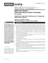
Figure 1 – 8512831 8516563
8512831, 8516563
A
8512831
8516563
INSTRUCTION MANUAL
ANSI Z359.1
This manual is intended to meet the Manufacturer’s Instructions as required by ANSI Z359.1
and should be used as part of an employee training program as required by OSHA

2
1. SPECIFICATIONS
DESCRIPTION:
The DBI-SALA Center Mount Concrete Sleeves are
designed for mounting to horizontal concrete or steel
structures.
A
THESE BASES ARE ONLY COMPATIBLE WITH DBI
SALA ADVANCED DAVIT MASTS AND EXTENSIONS.
IMPORTANT: All connecting systems, (self retracting lifelines, winches and energy absorbing lanyards) used
with the davit arm and base system shall limit the average arresting forces to 900 lbs (4 kN).
GENERAL SPECIFICATIONS - MODEL 8512831:
Capacity (one user)
Working Load Limit: Minimum 4:1 Safety Factor
450 lbs (205 kg)
Vertical Load
5000 lbs (22.2 kN)
MATERIALS & CONSTRUCTION:
General Construction Welded Steel
Material Mild Steel
Finish (Steel) Zinc Plated
Plating Specication ASTM Designation
B633, Type II, Class 1
APPLICATION RESTRICTIONS:
For use with Capital Safety Systems
products & accessories only.
Each installation must be approved to
local standards by a qualied engineer.
If base material does not meet the
minimum requirements, reinforcement
must be added to meet the minimum
requirements.
GENERAL SPECIFICATIONS - MODEL 8516563
Capacity (one user)
Working Load Limit: Minimum 4:1 Safety Factor
450 lbs (205 kg)
5000 lbs (22.2 kN)
Vertical Load
MATERIALS & CONSTRUCTION:
General Construction Stainless Steel
Material 304 SS
Finish (Stainless Steel) Brush Blast
Plating Specication None
APPLICATION RESTRICTIONS:
For use with Capital Safety Systems
products & accessories only.
Each installation must be approved to
local standards by a qualied engineer.
If base material does not meet the
minimum requirements, reinforcement
must be added to meet the minimum
requirements.

3
Figure 2 – Base Dimensions
4.00
TYP
4 in
10.2cm
0.5 in
1.3cm
.813 in
2.06cm
6.25 in
15.9cm
1.75 in
4.4cm
2 in
5.1cm
8 in
20.3cm
4.0 in
10.2cm
12.5 in
31.2cm
9 in
22.9cm
WARNING: The installers shall ensure the suitability of base materials into which structural anchor devices are
xed with every xation.
Where an anchor device is intended to be used exclusively for personal protective equipment, it should be
clearly marked by pictogram, or other clearly seen and understood marking, on or near the anchor device,
clearly stating that the devise is designed exclusively for use of personal protective equipment. Anchor devices
are only to be used with ANSI marked fall arrest systems, which will generate forces not to exceed average
arresting forces of 900 lbs (4kN) at the anchor device.
Due care should be taken to assess the suitability of all transportable temporary anchor devices and any
associated xings for the application in which it is to be used. The viability of any installation should be veriable
by a qualied engineer.
IMPORTANT: This base is not designed for welding application, and should be bolted in place. For bases
designed to be welded in place, please contact Capital Safety.

4
2. MOUNTING REQUIREMENT MINIMUMS
Table 1 – Mounting Requirement Minimums
29 inches (73.6cm) Offset
44 inches (112cm) Offset
Max Pullout Force Per Fastener 5,700 lb (25.4 kN) 6,750 lb (30.0 kN)
Shear Force N/A N/A
Max Moment Load on Structure 76,000 lbs*in (8.6 kN *m) 90,000 lb*in (10.2 kN*m)
Max Vertical Load on Structure 5,000 lbs (22.2 kN) 5,000 lbs (22.2 kN)
STRUCTURE
XX.XX
REFER TO
FASTENER
MANUFACTURER
SPECIFICATIONS
XX.XX
REFER TO
FASTENER
MANUFACTURER
SPECIFICATIONS
(MINIMUM)
(MINIMUM)
* NOTE: Meets OSHA requirements for engineered anchor points.
NOTE: These numbers are based on a safety factor of 2:1. Refer to the fastener manufacturer specications for
fastener safety factors. Capital Safety recommends maintaining at least a safety factor of 2:1. Multiple safety
factors must be taken into account when determining fasteners.
IMPORTANT: Base installation must be approved to local regulations by a qualied engineer. Refer to the
fastener manufacturer for location of the fasteners, structure thickness, and structure type requirements.
WARNING: Failure to follow Mounting Requirement Minimums and Installation instructions may lead to severe
injury and/or death.

5
3. INSTALL
WARNING: It is imperative that the base be installed perpendicular to the ground. Severe injury and/or death
may result if the base is installed incorrectly. If there are any questions pertaining to the installation or the
base in general, contact Capital Safety.
WARNING: Failure to follow Mounting Requirement Minimums and Installation instructions may lead to severe
injury and/or death.
IMPORTANT: All mounting hardware must be able to withstand a minimum pull out force of 6,750 lbs (30.0
kN) each if using a 44 inches (112cm) offset. If a 29 inches (73.6cm) offset is used, a minimum pullout 5,700
lbs (25.4 kN) is required. See Table 1 for specic installion guidelines. (2:1 safety factor.)
1. Place davit base upright and perpendicular to the ground. (See Figure 3 below.) Using a Specication
approved drill bit and the davit base as a guide, drill four holes into the structure.
IMPORTANT: A qualied engineer must verify the structural installation meets local and federal regulations
IMPORTANT: A qualied engineer must recommend the appropriate fasteners and determine proper base
placement on the mount structure.
2. Using a Specication approved drill bit based on the fastener chosen, and using the davit base as a guide,
drill four holes into the deck.
3. Install the Specication approved hardware.
4. Inspect davit base to ensure that it is secure and pependicular to ground.
Figure 3 – Install Method
.25
Reference Fastener Mounting
Requirement Minimums
Edge / Fall
Reference
Fastener
Mounting
Requirement
Minimums
Edge / Fall

6
4. DAVIT BASE INSPECTION:
BEFORE EACH USE:
IMPORTANT: Extreme working conditions (harsh environments, prolonged use) may require increasing the
frequency of inspections.
WARNING: If the base has been subjected to fall arrest forces, it must be immediately removed from service
and inspected. If the oor mount base fails inspection, remove from service and destroy, or contact Capital
Safety for repair or replacement.
Table 2 – Inspection and Maintenance Log
Serial Number(s): Date Purchased:
Model Number: Date of First Use:
Inspected By: Inspection Date:
Component: Inspection:
Authorized
Person or
Rescuer
Competent
Person
Davit Base
Ensure all bolts are secure and not damaged.
Base should be inspected directly after installation and at same intervals as
the arresting system for similar defects and/or unsafe conditions.
All labels must be present and fully legible.
If inspection reveals an unsafe or defective condition, remove the base from
service and destroy, or contact Capital Safety for repair or replacement.
Look for signs of corrosion on the entire unit.
Corrective Action/Maintenance: Approved By:
Date:
Corrective Action/Maintenance: Approved By:
Date:
Corrective Action/Maintenance: Approved By:
Date:
Corrective Action/Maintenance: Approved By:
Date:
Corrective Action/Maintenance: Approved By:
Date:
Corrective Action/Maintenance: Approved By:
Date:
Corrective Action/Maintenance: Approved By:
Date:
Corrective Action/Maintenance: Approved By:
Date:
Corrective Action/Maintenance: Approved By:
Date:
Corrective Action/Maintenance: Approved By:
Date:
Corrective Action/Maintenance: Approved By:
Date:
Corrective Action/Maintenance: Approved By:
Date:
Corrective Action/Maintenance: Approved By:
Date:
Corrective Action/Maintenance: Approved By:
Date:

7
Corrective Action/Maintenance: Approved By:
Date:
Corrective Action/Maintenance: Approved By:
Date:
Corrective Action/Maintenance: Approved By:
Date:
Corrective Action/Maintenance: Approved By:
Date:
Corrective Action/Maintenance: Approved By:
Date:
Corrective Action/Maintenance: Approved By:
Date:
Corrective Action/Maintenance: Approved By:
Date:
Corrective Action/Maintenance: Approved By:
Date:
Corrective Action/Maintenance: Approved By:
Date:
Corrective Action/Maintenance: Approved By:
Date:
Corrective Action/Maintenance: Approved By:
Date:
Corrective Action/Maintenance: Approved By:
Date:
5. DAVIT BASE LABELS
A
B
WARNING/AVERTISSEMENT
This component is rated for a work ing load of
450 lb. (205 kg). Retractable devices or shock absorbers
must have an AVERAGE ARRESTING FORCE OF 900 lb. (4kN)
OR LESS, to provide a safety factor of 2:1. System rating is
that of the lowest rated system component.
Cette composant est conçu pour une charge de travail de
450 lb (205 kg). Des dispositifs rétractables ou amortisseurs
doit avoir une moyenne force d’arret de 900 lb (4 kN) ou
moins, pour fournir un facteur de sécurité de 2:1.
Classement du Système est celui de la composante plus
bas nominale système
A
B

ISO
9001
USA
3833 SALA Way
Red Wing, MN 55066-5005
Toll Free: 800.328.6146
Phone: 651.388.8282
Fax: 651.388.5065
solutions@capitalsafety.com
Brazil
Rua Anne Frank, 2621
Boqueirão Curitiba PR
81650-020
Brazil
Phone: 0800-942-2300
brasil@capitalsafety.com
Mexico
Calle Norte 35, 895-E
Col. Industrial Vallejo
C.P. 02300 Azcapotzalco
Mexico D.F.
Phone: (55) 57194820
mexico@capitalsafety.com
Colombia
Compañía Latinoamericana de Seguridad S.A.S.
Carrera 106 #15-25 Interior 105 Manzana 15
Zona Franca - Bogotá, Colombia
Phone: 57 1 6014777
servicioalcliente@capitalsafety.com
Canada
260 Export Boulevard
Mississauga, ON L5S 1Y9
Phone: 905.795.9333
Toll-Free: 800.387.7484
Fax: 888.387.7484
info.ca@capitalsafety.com
EMEA (Europe, Middle East, Africa)
EMEA Headquarters:
5a Merse Road
North Moons Moat
Redditch, Worcestershire
B98 9HL UK
Phone: + 44 (0)1527 548 000
Fax: + 44 (0)1527 591 000
csgne@capitalsafety.com
France:
Le Broc Center
Z.I. 1re Avenue - BP15
06511 Carros Le Broc Cedex
France
Phone: + 33 04 97 10 00 10
Fax: + 33 04 93 08 79 70
information@capitalsafety.com
Australia & New Zealand
95 Derby Street
Silverwater
Sydney NSW 2128
Australia
Phone: +(61) 2 8753 7600
Toll-Free : 1800 245 002 (AUS)
Toll-Free : 0800 212 505 (NZ)
Fax: +(61) 2 8753 7603
sales@capitalsafety.com.au
Asia
Singapore:
69, Ubi Road 1, #05-20
Oxley Bizhub
Singapore 408731
Phone: +65 - 65587758
Fax: +65 - 65587058
inquiry@capitalsafety.com
Shanghai:
Rm 1406, China Venturetech Plaza
819 Nan Jing Xi Rd,
Shanghai 200041, P R China
Phone: +86 21 62539050
Fax: +86 21 62539060
inquiry@capitalsafety.cn
www.capitalsafety.com
LIMITED LIFETIME WARRANTY
Warranty to End User: D B Industries, LLC dba CAPITAL SAFETY USA (“CAPITAL SAFETY”)
warrants to the original end user (“End User”) that its products are free from defects in materials and
workmanship under normal use and service. This warranty extends for the lifetime of the product
from the date the product is purchased by the End User, in new and unused condition, from a CAPITAL
SAFETY authorized distributor. CAPITAL SAFETY’S entire liability to End User and End User’s exclusive
remedy under this warranty is limited to the repair or replacement in kind of any defective product
within its lifetime (as CAPITAL SAFETY in its sole discretion determines and deems appropriate). No oral
or written information or advice given by CAPITAL SAFETY, its distributors, directors, offi cers, agents
or employees shall create any different or additional warranties or in any way increase the scope of
this warranty. CAPITAL SAFETY will not accept liability for defects that are the result of product abuse,
misuse, alteration or modifi cation, or for defects that are due to a failure to install, maintain, or use the
product in accordance with the manufacturer’s instructions.
CAPITAL SAFETY’S WARRANTY APPLIES ONLY TO THE END USER. THIS WARRANTY IS THE ONLY
WARRANTY APPLICABLE TO OUR PRODUCTS AND IS IN LIEU OF ALL OTHER WARRANTIES AND
LIABILITIES, EXPRESSED OR IMPLIED. CAPITAL SAFETY EXPRESSLY EXCLUDES AND DISCLAIMS
ANY IMPLIED WARRANTIES OF MERCHANTABILITY OR FITNESS FOR A PARTICULAR PURPOSE, AND
SHALL NOT BE LIABLE FOR INCIDENTAL, PUNITIVE OR CONSEQUENTIAL DAMAGES OF ANY NATURE,
INCLUDING WITHOUT LIMITATION, LOST PROFITS, REVENUES, OR PRODUCTIVITY, OR FOR BODILY
INJURY OR DEATH OR LOSS OR DAMAGE TO PROPERTY, UNDER ANY THEORY OF LIABILITY, INCLUDING
WITHOUT LIMITATION, CONTRACT, WARRANTY, STRICT LIABILITY, TORT (INCLUDING NEGLIGENCE) OR
OTHER LEGAL OR EQUITABLE THEORY.
/