281

Duerkopp Adler 281 User manual

  • Hello! I am an AI chatbot trained to assist you with the Duerkopp Adler 281 User manual. I’ve already reviewed the document and can help you find the information you need or explain it in simple terms. Just ask your questions, and providing more details will help me assist you more effectively!
  • What are the components of the repair kit 0281 801293?
    How do I remove the needle bar?
    How do I mount the new bushings?
    How do I mount the dismantled parts?
Ausgabe/Edition
:
07.2017
Printed in Germany
Ä
nderungsindex
Rev. index: 01.0
1 Komponenten des Teilesatzes 0281 801293
Pos. Anzahl Bezeichnung Teilenummer
1 1 Reparaturanleitung (0791 281771)
2 1 Kleber Loctite 603** (9083 900030)
3 1 Windeeisen (9083 900020)
4 1 Fluchtdorn (0281 801320)
5 1 Reibahle (9083 900010)
6 1 Einschlagdorn (0281 801300)
7 1 Inbusschlüssel (9083 900040)
8* 1 Nadelstange Nadel 134/ Kolben 2,0 mm (0281 120104)
0 Nadelstange Nadel DBx1/ Kolben 1,62 mm (0281 120204)
9* 1 Buchse unten (0281 120050)
10* 1
Buchse oben Klasse 281
Klasse 650
(02
81 120040)
(0650 120010)
* Die Teile der Positionen 8, 9 und 10 müssen bei Reparatur von mehr als einer
Maschine in entsprechender Anzahl nachbestellt werden.
** Bitte beachten Sie die richtige Lagerung des Klebers!
Er muss, wenn er mehrfach über einen längeren Zeitraum verwendet werden soll, kühl
gelagert werden.
Außerdem ist unbedingt das auf der Flasche angegebene Haltbarkeitsdatum zu
beachten.
Reparaturanleitung Nadelstange
Bausatz (0281 801293)
Repairing Instructions Needle Bar
Kit (0281 801293)
Teile-Nr./ Part-No.:
0791 281771
Blatt: von
Sheet: 1 from 8
11
1
Klemmkloben (0981 150002)
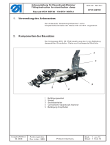
2 Demontage der Nadelstange
Kopfdeckel 1 und Fadenhebelabdeckung 2 entfernen.
Schrauben 6 für den Fadenhebellenkerbolzen 5 lösen.
Bolzen 5 mit einer Kopfdeckelschraube herausziehen.
Nadel entfernen und Fadenführung an der Nadelstange
demontieren.
Schraube 3 des Nadelstangenklemmklobens lösen und
Nadelstange 4 nach oben herausziehen.
Befestigungsschrauben 8 der Kurbel auf der Armwelle 7 lösen.
Kurbel 10 mit Fadenhebel 9 und Nadelstangentrieb 11 nach
vorn herausbauen.
Reparaturanleitung Nadelstange
Bausatz (0281 801293)
Repairing Instructions Needle Bar
Kit (0281 801293)
Teile-Nr./ Part-No.:
0791 281771
Blatt: von
Sheet: 2 from 8
A
usgabe/Edition:
07.2017
Änderungsindex
Rev. i
ndex: 01.0
Printed in Germany
1
2
6
5
43
10 8 7
11 10 9
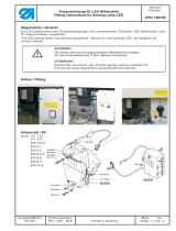
Obere N adelstangenbuchse 13 mit Montagedorn 12 nach unten
herausschlagen.
Untere Nadelstangenbuchse 14 nach unten herausschlagen.
Obere Armbohrung 15 mit Reibahle 16 von Kleberesten
freireiben.
3 Neue Buchsen montieren
Untere Nadelstangenbuchse 17 von oben mit Montagedorn 12
einschlagen.
Reparaturanleitung Nadelstange
Bausatz (0281 801293)
Repairing Instructions Needle Bar
Kit (0281 801293)
Teile-Nr./ Part-No.:
0791 281771
Blatt: von
Sheet: 3 from 8
A
usgabe/Edition:
07.2017
Printed in Germany
Ä
nderungsindex
Rev. index: 01.0
13 12
14 16 15
17
9,5 mm (Klasse 281)
Klasse 281: Maß 9,5mm
Klasse 650: der Markierung auf dem Einschlagdorn folgen
Fl
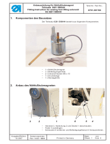
uchtdorn 19 in die untere Buchse 18 einsetzen und
überprüfen, dass die obere Buchse 20 sich auf dem
Fluchtdorn geführt ohne jeden Kontakt zur Gehäusebohrung
einführen lässt.
Oberteil nach hinten klappen.
Obere Nadelstangenbuchse 20 entfetten.
Obere Nadelstangenbuchse 20 mit Loctite 603 gleichmäßig
benetzt unter Drehen in die Gehäusebohrung einschieben und
10 min aushärten lassen (Maß 0,8mm)
Klebeergebnis / Flucht mit Fluchtdorn nach dem Aushärten
überprüfen.
Dorn muss ohne jeden Widerstand und ohne Anstoßen sehr
leicht bewegbar sein!
4 Demontierte Teile wieder einbauen.
Kurbel auf Armwelle montieren, dabei Fadenhebel auf Mitte
Schlitz stellen und die Befestigungsschrauben sehr sauber auf
den Flächen der Armwelle zentrieren.
Nadelstange (Kap 5. der Serviceanleitung beachten) einbauen
und mit etwas Fett an den Buchsen versorgen.
Fadenhebellenkerbolzen s o wieder einsetzen, dass er ca.
0,5 mm hinter der Armfläche positioniert ist.
Schleifenhubstellung des Greifers und Zeitpunkt der FA-Kurve
überprüfen und ggfs. korrigieren.
Kopfdeckel und Fadenhebelabdeckung montieren.
Reparaturanleitung Nadelstange
Bausatz (0281 801293)
Repairing Instructions Needle Bar
Kit (0281 801293)
Teile-Nr./ Part-No.:
0791 281771
Blatt: von
Sheet: 4 from 8
A
usgabe/Edition:
07.2017
Änderungsindex
Rev. i
ndex: 01.0
Printed in Germany
20 19 18
20
0
,
8
m
m
Ausgabe/Edition
:
07.2017
Printed in Germany
Ä
nderungsindex
Rev. index: 01.0
1 Kit components 0281 801293
Pos. Qty Designation Part No.
1 1 Repairing Instructions (0791 281771)
2 1 Glue Loctite 603** (9083 900030)
3 1 Tap wrench (9083 900020)
4 1 Aligning mandrel (0281 801320)
5 1 Reamer (9083 900010)
6 1 Drift punch (0281 801300)
7 1 Allen key (9083 900040)
8* 1 Needle bar Needle 134/ Shank 2.0 mm (0281 120104)
0 Needle bar Needle DBx1/ Shank 1.62 mm (0281 120204)
9* 1 Lower bushing (0281 120050)
10* 1
Upper bushing
class 281
class 650
(0
281 120040)
(0650 120010)
* If more than one machine has to be repaired, the parts with the positions 8, 9 and 10
must be ordered correspondingly.
** Please observe the correct storage of the glue!
If you intend to use it several times over a long period of time, then it should be
stored in a c ool place.
In addition, it is imperative to observe the validity date indicated on the container.
Reparaturanleitung Nadelstange
Bausatz (0281 801293)
Repairing Instructions Needle Bar
Kit (0281 801293)
Teile-Nr./ Part-No.:
0791 281771
Blatt: von
Sheet: 5 from 8
11
1
Clamping block (0981 150002)
2 Removing the needle bar
Remove the face c over 1 and the thread lever cover 2.
Loosen the screws 6 for the thread lever driver 5.
Pull out the pin 5 using one of the screw of the face cover.
Remove the needle and take out the thread guide on the needle
bar.
Loosen the screw 3 of the needle bar clamp block and pull out
the needle bar 4 upwards.
Loosen the fastening screws 8 of the crank on the arm shaft 7.
Remove the crank 10 with the thread lever 9 and the needle bar
drive 11 from the front.
Reparaturanleitung Nadelstange
Bausatz (0281 801293)
Repairing Instructions Needle Bar
Kit (0281 801293)
Teile-Nr./ Part-No.:
0791 281771
Blatt: von
Sheet: 6 from 8
A
usgabe/Edition:
07.2017
Änderungsindex
Rev. i
ndex: 01.0
Printed in Germany
1
2
6
5
43
10 8 7
11 10 9
Remove the needle bar bushing 13 by using the drift punch 12
and by punching it downwards.
Punch also the lower needle bar bushing 14 downwards.
Remove the glue remainder on the bore hole in the arm 15
using the reamer 16.
3 Mounting the new bushings
Punch the lower needle bar bushing 17 from top using the drift
pun
ch 12.
Reparaturanleitung Nadelstange
Bausatz (0281 801293)
Repairing Instructions Needle Bar
Kit (0281 801293)
Teile-Nr./ Part-No.:
0791 281771
Blatt: von
Sheet: 7 from 8
A
usgabe/Edition:
07.2017
Printed in Germany
Ä
nderungsindex
Rev. index: 01.0
13 12
14 16 15
17
9.5 mm (class 281)
class 281:
measurement 9.5 mm
c
lass 650: follow the marking on the drift punch
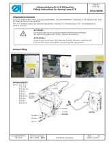
Insert the a
ligning mandrel 19 in the lower bushing 18 and
make sure that the upper bushing 20 is loose fit in the bore
hole of the housing when pushed upwards.
Tilt the machine backwards.
Degrease the upper bushing 20.
Apply uniformly the Loctite 603 on the upper bushing 20, and
insert it in the bushing bore of the housing and allow to harden
for 10 minutes (measurement 0.8 mm).
Glueing result / Check the alignment of the aligning mandrel
after hardening.
The aligning mandrel must be able to move freely!
4 Mounting the dismantled parts
Mount the crank on the arm shaft, at the same time position the
thread lever in the middle of the slit and center the very clean
fastening screw on the flat surface of the arm shaft.
Mount the needle bar (pay attention to the chapter 5 of the
service instructions) and grease the bushing.
Insert the thread lever pin again, so that it is positioned 0.5 mm
behind the arm surface.
Check the loop stroke of the hook and the timing of the thread
trimmer cam and correct it if needed.
Mount the face cover and thread lever c over.
Reparaturanleitung Nadelstange
Bausatz (0281 801293)
Repairing Instructions Needle Bar
Kit (0281 801293)
Teile-Nr./ Part-No.:
0791 281771
Blatt: von
Sheet: 8 from 8
A
usgabe/Edition:
07.2017
Änderungsindex
Rev. i
ndex: 01.0
Printed in Germany
20 19 18
0
.
8
m
m
20
/