Page is loading ...

For questions or help with this product contact Tech Support at (570) 546-9663 or techsupport@grizzly.com
MODEL H8088
2-STAGE
TRANSMISSION JACK
INSTRUCTIONS
COPYRIGHT © DECEMBER, 2006 BY GRIZZLY INDUSTRIAL, INC., REVISED JULY, 2016 (KB)
NO PORTION OF THIS MANUAL MAY BE REPRODUCED IN ANY SHAPE
OR FORM WITHOUT THE WRITTEN APPROVAL OF GRIZZLY INDUSTRIAL, INC.
(FOR MODELS MFD. SINCE 11/14) #KBWK18294 PRINTED IN CHINA
V2.07.16
This jack is designed to assist in transmis-
sion removal only. Failure to follow these
instructions when using the transmission
jack could result in serious personal injury
or death:
1. Only use this jack on hard level surfaces
such as concrete or asphalt.
2. DO NOT overload this jack beyond the
maximum lifting capacity. Overloading
can cause the jack to collapse.
3. DO NOT use this jack to lift or support a
vehicle.
4. Keep fingers and hands away from pinch
points when lowering.
5. Only transport load with jack platform in
the lowered position and properly secured
with chain.
6. Center load on jack for stability.
7. Always use safety chain to secure load
immediately after placing it on jack.
Specifications
Maximum Lifting Capacity .................... 1,100 lbs.
Lifting Range ........................................34"–71
3
⁄8"
Weight .....................................................138 lbs.
Anyone removing or replacing a transmission
under a lift will appreciate having this 2-Stage
Transmission Jack. A foot activated pump raises
this jack from 34" to 71
3
⁄8", freeing hands to guide
the jack and safely secure the transmission. Its
wide base with 4 steel casters provide plenty of
stability and a swivel tow handle make it highly
maneuverable in the lowered position.
Introduction

-2-
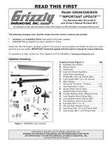
H8088 2-Stage Transmission Jack (Mfd. 01/11)
Primary Components Qty
A. Half-Circle Handle ...................................... 1
B. Leg ............................................................. 2
C. Angle Iron Bracket ...................................... 2
D. Platform Assembly ..................................... 1
E. Pump Assembly ......................................... 1
Inventory
Boxed Components Qty
F. Chain 9mm ID, 28 Link ............................... 2
G. Caster Wheels M12-1.75 x 25 Stud ............ 4
H. Cap Screws M16-2 x 75 ............................. 4
I. Lock Washers 16mm .................................. 4
J. Flat Washers 16mm ................................... 4
K. Flat Washers 12mm ................................... 4
L. Lock Washers 12mm .................................. 4
M. Acorn Nuts M12-1.5 .................................... 4
N. Chain Mount Plates .................................... 4
O. Threaded Rod Ends M10-1.5 x 14, 16 x 31 2
P. Wing Nuts M10-1.5 ..................................... 2
Q. Anchor Bolts M8-1.25 x 10⁸ ....................... 2
R. Flat Washers 8mm ..................................... 2
S. Hex Nuts M8-1.25 ....................................... 2
T. Wing Nuts M8-1.25 ..................................... 2
U. Hex Bolts M8-1.25 x 25 .............................. 2
V. Hex Bolts M10-1.5 x 25 .............................. 6
W. Flat Washers 10mm ................................... 8
X. Hex Nuts M10-1.5 ....................................... 8
A
B
C
D
E
Figure 1. H8088 primary components.
Figure 2. H8088 boxed components.
F
H
N
P
Q
V
U
X
T
O
R S
W
ML
K
J
I
G

H8088 2-Stage Transmission Jack (Mfd. 01/11)
-3-
1. Attach casters to legs using (1) 12mm flat
washer, 12mm lock washer, and M12-1.75
acorn nut on each (see Figure 3).
2. Attach each leg to pump assembly with (2)
M16-1.75 x 70 cap screws, 16mm flat wash-
ers, and 16mm lock washers (see Figure 4).
3. Secure half-circle handle on top edge of
pump assembly (see Figure 5) with pre-
installed hex nuts and bolts.
4. Set platform assembly on top of pump assem-
bly ram and tighten pre-installed hex bolt (see
Figure 6).
Assembly
Figure 5. Half-circle handle secured at top of
pump assembly.
Half-Circle
Handle
Pump
Assembly
Figure 3. Caster attached to leg before
tightening acorn nut.
Leg
M12-1.75
Acorn Nut
12mm Lock
Washer
12mm Flat
Washer
Figure 4. Legs attached to pump assembly.
Pump Assembly
Leg
Cap
Screws
Tools Needed for Assembly Qty
Hex Wrench 12mm ............................................ 1
Wrench 14mm ................................................... 1
Wrench 17mm.................................................... 1
Wrench 19mm ................................................... 1
Figure 6. Platform assembly mounted to pump
assembly ram (chain mount plates, chains, and
anchor bolt shown attached).
Platform
Assembly
Pre-installed
Hex Bolt
Pump
Assembly
Ram
Assembling the Jack

-4-
H8088 2-Stage Transmission Jack (Mfd. 01/11)
5. Attach an angle-iron bracket to each side of
platform assembly. Place (1) M10-1.5 x 25
hex bolt through hole in angle iron bracket
and slot in platform. Secure from below with
(1) 10mm flat washer and M10-1.5 hex nut
(see Figure 7).
6. Install (2) chain mount plates on inside edges
of each angle-iron bracket with (1) M10-1.5 x
25 hex bolt, 10mm flat washer, and M10-1.5
hex nut, as shown in Figure 8.
Figure 8. Chain mount plates attached to angle-
iron bracket.
7. Attach (1) threaded rod end to each chain
mount plate with (1) 10mm flat washer and
M10-1.5 wing nut, as shown in Figure 9.
8. Slide threaded end of anchor bolt through rod
end and attach with M8-1.25 wing nut (see
Figure 9).
9. Place M8-1.25 x 25 hex bolt through open
bolt hole in chain mount plate. Attach last
chain link with 8mm flat washer and M8-1.25
hex nut (see Figure 10). Repeat for opposite
corner. Chain connects to unthreaded end of
anchor bolt to secure load to platform.
Figure 7. M10-1.5 hex nut secures angle-iron
bracket to platform below. Slot allows horizontal
adjustment in platform.
Hex
Nut
Figure 9. Threaded rod end and anchor bolt
attached to chain mount plate.
Anchor Bolt M8-1.25
Wing Nut
Chain Mount
Plate
Threaded
Rod End
M10-1.5
Wing Nut
Figure 10. Chain bolted to chain mount plates.
Chain
Mount
Plates
Chain
Angle-Iron
Bracket
Chain Mount Plates
Hex Bolts

H8088 2-Stage Transmission Jack (Mfd. 01/11)
-5-
Operation
Pump Control Handle (Figure 11): Point to the
left to allow the jack platform to lift when pumped.
Point to the right to lower the jack. (If the jack
holds a heavy load, turn very slowly to control the
lowering rate and avoid dropping the load.)
Foot Pedal Pump (Figure 11): When moved
up and down, the foot pedal pump lifts the jack
platform.
Platform Adjustment Knobs (Figure 11):
Located under the jack platform, these knobs
allow for precision placement and leveling of the
loaded platform. The upper knob adjusts the plat-
form's lateral movement. The lower knob adjusts
the platform's tilt.
Figure 11. H8088 2-Stage Transmission Jack
operational components.
Figure 12. Chain attachment and platform
adjustments.
Platform Adjustments (Figure 12): Slide the
angle iron brackets to adjust for the width of the
transmission. Use the lateral adjustment knob and
tilt adjustment knob to help mount the transmis-
sion to the engine.
Chain Adjustments (Figure 12): Slide the chain
mount plates fore and aft on the angle iron bracket
to adjust the chain length for the height of the
transmission in a cross pattern as shown. Adjust
orientation of threaded rod ends and anchor bolts
as needed. Tighten all hex nuts on chain mount
plates and wing nuts on threaded rod ends before
loading the platform. Place each open end of
chain onto anchor bolt and tighten its wing nut to
secure the load before lowering.
Platform
Foot Pedal
Pump
Lateral
Adjustment
Tilt
Adjustment
Pump Control
Handle

-6-
H8088 2-Stage Transmission Jack (Mfd. 01/11)
If the jack becomes "spongy" or will not rise
when pumped, air bubbles may be trapped in the
pump assembly's hydraulic system. These can be
removed by following the instructions below.
Bleeding the Pump
Figure 13. Air-vent fill hole allows for addition of
hydraulic fluid.
To remove air bubbles:
1. Remove the platform assembly.
2. Pump the foot pedal to expose about 4 inch-
es of the lower ram shaft.
3. With a rag, hold the ram shaft and turn the
collar counterclockwise until shaft threads
are visible.
4. Hold a rag below the collar and gently press
down on the foot pedal until fluid comes out.
Repeat as needed until the air bubbles stop
coming out in the hydraulic fluid.
5. When the fluid runs freely without air bubbles,
tighten the collar, wipe up spilled fluid, and
replace the platform assembly.
6. Remove the air-vent fill bolt and check the
fluid level. Add fluid if necessary.
Air-Vent
Fill Bolt
The Model H8088 will require additional hydraulic
fluid after long-term use. This will be noticeable if
the jack will not reach its maximum height.
Maintenance
To add hydraulic fluid, remove the air-vent fill bolt,
shown in Figure 13, and add fluid until it reaches
the top of the fill hole.
Keep the hydraulic ram clean and free of any dust,
dirt, or foreign debris. Abrasive material stuck to
the ram can damage the hydraulic seal when the
ram is retracted back into the jack. Regularly wipe
the hydraulic ram clean with a lightly oiled rag.

H8088 2-Stage Transmission Jack (Mfd. 01/11)
-7-
6V2
18
19
33
32V2
12V2
31
10
3
35
1
2V2
2V2
5V2
3
1
3
34
1
36
36
1
4V2
17
17
7V2
24
24
25
25
25
25
15
15
15
15
15
15
17
17
17
17
23
23
22
22
21
21
8
8
38
38
26V2
26V2
39
39
11
11
9V2
17
17
17
17
16
16
16
16
15
15
15
15
3
16
16
37
37
16
16
16
16
16
16
36
36
4V2
4V2
4V2
5V2
5V2
5V2
34
34
34
35
35
35
H8088 Parts Breakdown and Parts List
REF PART # DESCRIPTION REF PART # DESCRIPTION
1 PH8088001 CASTER WHEEL M12-1.75 X 25 STUD 19 PH8088019 SET SCREW M6-1 X 10
2V2 PH8088002V2 LEG V2.01.11 21 PH8088021 WING NUT M8-1.25
3 PH8088003 ACORN NUT M12-1.75 22 PH8088022 ANCHOR BOLT M8-1.25 X 10⁸
4V2 PH8088004V2 LOCK WASHER 16MM 23 PH8088023 THREADED ROD END M10-1.5 X 14, 16 X 31
5V2 PH8088005V2 CAP SCREW M16-2 X 75 24 PH8088024 ANGLE IRON BRACKET
6V2 PH8088006V2 PUMP ASSEMBLY V2.01.11 25 PH8088025 CHAIN MOUNT PLATE
7V2 PH8088007V2 PLATFORM ASSEMBLY V2.01.11 26V2 PH8088026V2 HEX BOLT M8-1.25 X 25
8 PH8088008 CHAIN 9MM ID, 28 LINK 31 PH8088031 MACHINE ID LABEL
9V2 PH8088009V2 FOOT PEDAL V2.01.11 32V2 PH8088032V2 AIR VENT FILL BOLT M10-1 X 8 V2.01.11
10 PH8088010 EXT RETAINING RING 16MM 33 PH8088033 O-RING 7.7 X 1.9
11 PH8088011 HALF-CIRCLE HANDLE 34 PH8088034 LOCK WASHER 12MM
12V2 PH8088012V2 FOOT PEDAL PIN 16 X 60MM V2.01.11 35 PH8088035 FLAT WASHER 12MM
15 PH8088015 HEX BOLT M10-1.5 X 25 36 PH8088036 FLAT WASHER 16MM
16 PH8088016 FLAT WASHER 10MM 37 PH8088037 WING NUT M10-1.5
17 PH8088017 HEX NUT M10-1.5 38 PH8088038 HEX NUT M8-1.25
18 PH8088018 STEEL BALL 5MM 39 PH8088039 FLAT WASHER 8MM
Please Note: We do our best to stock replacement parts whenever possible, but we cannot guarantee that all parts shown here
are available for purchase. Call (800) 523-4777 or visit our online parts store at www.grizzly.com to check for availability.

-8-
H8088 2-Stage Transmission Jack (Mfd. 01/11)
/