
Installation and Operating Manual
Tank Sensor FW 120 For Tank Height 40 cm - 120 cm, 12 V / 24 V No. 0256
Tank Sensor FW 240 For Tank Height 80 cm - 240 cm, 12 V / 24 V No. 0258
Level Measuring Sensor for Water and Hydrous Media
The VOTRONIC Tank Sensor FW is a special development for water tanks in fire fighting vehicles. It allows exact
electric remote measurement of the tank level.
The sensor supplies electrical unit signals (voltage signal 0…10 Volts or current signal 4…20 mA) to the
connection of various display and evaluation units (even possible for several units):
Such as to the VOTRONIC remote indicator LED Tank Display, the VOTRONIC switching unit Multiswitch FW or to
external units, pointer indicators, board computers etc.
• Suitable for plastic and metal tanks
• No mechanically moved parts, fully electronic capacitive measuring method
• The electronic system is sealed waterproof and vibration-proof
• Free installation, also subsequently, at the upper side of the tank or near the tank for space reasons.
• Freely adjustable minimum and maximum levels.
• Independent of pressure, no falsification of measured values in case of pressure filling etc.
• Linear characteristic line of the filling height.
• Protection against wrong polarization, overvoltage, short-circuit and overload.
• Safety due to internal test procedures being executed continuously.
With 0…10 V operation, the Tank Sensor FW is able to manage up to 4 Remote Indicators VOTRONIC LED Tank
Display.
Safety Regulations:
Appropriate Application:
The Tank Sensor FW has been designed according to the valid safety regulations.
Appropriate application is restricted to:
1. Level measuring of water and hydrous media.
2. With extra low safety voltage.
3. In consideration of the indicated cable cross sections.
4. Observing the indicated fuse rates for the supplied operating voltage.
5. In technically faultless condition.
Never use the unit at locations where the risk of gas or dust explosion exists and don’t use it for safety related
applications!
• Cables are always to be laid in such a way that damage is excluded. Observe to fasten them tightly.
• The unit is to be disconnected from any connection prior to execution of electrically welding or work on the
electric system.
• The user/buyer is obliged to observe any construction and safety regulations.
• The unit is not equipped with parts, which can be replaced by the user.
• Non-observance may result in injury or material damage.
• The warranty period is 36 months from the purchase date (against presentation of the sales slip or invoice).
• The warranty will be void in case of any inappropriate utilisation of the unit, if it is used beyond the technical
specification, in case of improper operation or external intervention. We do not assume any liability for any
damage resulting hereof. The liability exclusion is extended to any service being executed by third, which has
not been ordered by us in writing. Service is to be effected exclusively by VOTRONIC Lauterbach / Germany.

- 2 -
Installation in the Tank, Measuring Cable “Probe“:
Position at the upper side of the tank, as centrically as possible at the tank (more accurate display in case of tilted
vehicle), however at a distance of at least 10 cm from the wash plates or the sidewalls of the tank. The probe cable
should not be placed at the walls, but it should be hanging freely.
The bushing of the probe cable through the upper side of the tank is insulated with a screwed cable gland of the size
PG7 or with similar cable bushings. The insulator cap of the probe cable should be floating by approx.
10-20 mm above the tank bottom (formation of sludge).
Note: The probe cable should never be touched by the filling stream during tank filling.
(If being touched by filling stream, the measured value would be too high).
Note: The probe cable should never float to the surface. In case of hydrous media, the drift of the probe
cable is sufficient. For pasty media, floating is to be avoided by an insulated, elastic bracing of the
probe cable towards the tank bottom.
Installation at the Tank, Connection “Common“ (See Connection Plan):
A safe function of the tank sensor FW is ensured by a conductive connection of the terminal "Common" to the
liquid tank contents by way of a metal part.
In case of metal tanks this connection is to be effected directly to the metal tank wall.
Plastic Tanks (refer to connection plan):
a.) The conductive connection is effected by means of the pump or an existing connecting flange at the lower side
of the tank, since these parts are usually made of metal, and a cable lug can be screwed underneath.
b.) A stainless steel screw with the largest surface possible is to be screed down at the bottom-most of the tank.
Installation Tank Sensor FW:
Install the sensor close to the tank bushing of the probe cable (at the tank or directly near the tank).
Observe, that the length of the probe cable outside the tank should be as short as possible (if possible, shorter than
20 % of the tank height) to ensure high measuring accuracy (in case of soiling, moistening).
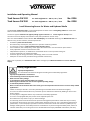
Connection for Operating Mode: Voltage Output 0…10 V:
Push each of the 4 micro slide switches to the right (towards the light-emitting diode)!
Verification: The light-emitting diode (green) is lighting continuously after supply of the operating
voltage!
Terminal
No.
Connecting
Terminal Operation Cable Type, Cross Section Remark
1 Probe Probe measuring cable,
hanging in the tank Special strand, highly flexible Shorten to the length
after installation of all
components!
2 Common
Conductive connection to
the tank contents Strand (1.0-2.5 mm²)
3 - Ground Battery -,
Car Body Ground
Three-core light plastic-
sheathed Cable
(Three-wire System)
0.5-1.0 mm²,
Outside diameter, max. 6 mm
for screwed cable gland PG7
“Display“
Ground
4 Signal
0..10 V
Output Signal
(towards Terminal 3,
- Ground):
0 Volt = empty
10 Volts = Full
Minimum load by
display units/evaluation
components (several
units being connected in
parallel) 1 kOhm
5 +12...24 V Battery +
Plus Operating Voltage
11 V - 32 V
(Insert Fuse 3 A)

- 3 -
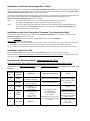
Connection Plan, Operating Mode Voltage Output 0…10 V:
Connection “Common“ by Metal Flange:
Connection “Common“ by Stainless Steel Screw:
Do not install the residual “probe” line outside of the tank too close to the tank wall, other
pipes or metallic objects and keep dry.

- 4 -
Connection for Operating Mode: Voltage Output 4…20 mA:
Push each of the 4 micro slide switches to the left (towards the adjusting device)!
Verification: The light-emitting diode (green) is not lighting after supply of the operating voltage!
Terminal
No.
Connecting
Terminal Operation Cable Type, Cross Section Remark
1 Probe Probe measuring cable,
hanging in the tank Special strand, highly flexible Shorten to the length
after installation of all
components!
2 Common
Conductive connection to
the tank contents Strand (1.0-2.5 mm²)
3 -4...20 mA
Cable to the display
4..20 mA
(related to ground)
Two-core light plastic-
sheathed cable
(Two-wire system)
0.5-1.0 mm²,
Outside diameter, max. 6 mm
for screwed cable gland PG7
“Display“
Maximum Load =
(O V-7 V) / 20 mA
e. g. max. 200 Ohms at
O V = 11 V
4 NC leave free --
5 +4...20 mA Battery +
UB
Plus Operating Voltage
O V = 11 V-32 V
(Insert Fuse 3 A)

- 5 -
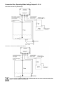
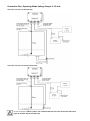
Connection Plan, Operating Mode Voltage Output 4…20 mA:
Connection “Common“ by Metal Flange:
Connection “Common“ by Stainless Steel Screw:
Do not install the residual “probe” line outside of the tank too close to the tank wall, other
pipes or metallic objects and keep dry.

- 6 -
Level Adjustment:
Two setting screws “Adjust” for “Full” and ”Empty” adjustment are located within the tank sensor FW.
The range of action of these setting screws is 15 rotations. They do not have a limit stop, so overwinding is
excluded.
Note: Rotation to the right (clockwise) means more signal, anticlockwise rotation means less signal. Adjuster
“Full“ slightly affects the adjuster ”Empty“. Therefore, start with ”Full“.
1.) Setting “Full”:
1. Fill the tank until the desired maximum level is reached.
2. Use the adjuster ”Full“ at the Votronic LED Tank Display and set 100 % or set the signal 10.0 V or 20.0 mA at
other display units.
2.) Setting “Empty”:
1. Evacuate the tank to the desired minimum level.
2. Use the adjuster “Empty“ at the Votronic LED Tank Display and set the desired minimum display
0.0 % - 10.0 % or set the signal 0.0 V - 1.0 V or 4.0 mA - 5.6 mA at other display units.
Check again and correct, if required. The set-up procedure is finished
Maintenance:
The unit is maintenance-free.
We recommend to checking the unit and the connected components periodically to ensure reliable operation and
extended lifetime.
Check the connections (clamping joints),
Check for soiling and humidity (tracking current).

- 7 -
Failure Corrective Action:
Operating Mode Voltage Output 0…10 V:
No reaction of display:
a) Battery connection or fuse defective, light-emitting diode in the sensor does not light - check
b) Cable “Signal (0…10 V)“ interrupted - check
c) Cable “Signal (0…10 V)“: Short-circuit to ground - check
d) Cable “+ 12-24 V“ interrupted - check
e) “Common“ does not have any contact or very bad contact with liquid - check
Constant display of 100 % on the display unit:
a) Cable “– Ground“ is interrupted - check
b) Cable “Signal (0…10 V)“: Short-circuit to ground + 12-24 V - check
c) Contact of the insulated ”Probe“ cable with water (silicone cap leaky or dropped off, damaged insulation)
- check, replace cable, if required.
Error messages:
a) Bad contact of cable “– Ground“ - check
b) Residual probe cable outside the tank badly soiled or watered - clean
c) Residual “probe” line outside of the tank: installed too close to the tank wall, other pipes, metallic or wet
objects - bare, or dry
d) “Probe“ cable in the tank strongly furred by media residues - clean
Operating Mode Current Output 4…20 mA:
No reaction of display:
a) Battery connection or fuse defective - check
b) Cable “+4..20 mA“ interrupted - check
c) Cable “4..20 mA“ interrupted - check
d) “Common“ does not have any contact or very bad contact with liquid - check
Constant display of 100 % on the display unit:
a) Contact of the insulated ”Probe“ cable with water (silicone cap leaky or dropped off, damaged insulation)
- check, replace cable, if required.
Error messages:
see above a) - d)
Notes:

- 8 -
Technical Data:
Operating Mode: Voltage Output 0…10 V Current Output 4…20 mA
Operating Voltage (OV): 12 V / 24 V 12 V / 24 V
Board Voltage Range: 10.8 V - 33.0 V 7.0 V - 33.0 V
Current Consumption: max. 30 mA 4…20 mA
Output Signal: 0…10 V, Three-wire System 4…20 mA, Two-wire System
Load: min. 1 kOhm max.: (OV - 7 V) / 20 mA
e. g.: (11 V -7 V) / 20 mA = 200 Ohm
Adjustable Tank Height:
FW 120: 40 cm - 120 cm
FW 240: 80 cm - 240 cm
Temperature Range: -20 °C .. +60 °C
Protection Class/System of Protection: IP 67
Dimensions: 98 x 64 x 38 mm
Weight: 180 g
Declaration of Conformity:
In accordance with the provisions of the statutory requirements and the relevant directives,
Electrical Equipment (Safety) Regulations 2016, Electromagnetic Compatibility Regulations 2016, The
Restriction of the Use of Certain Hazardous Substances in Electrical and Electronic Equipment
Regulations 2012 this product complies with the following standards or normative documents:
BS EN55014-1; BS EN61000-6-1; BS EN61000-4-2; BS EN61000-4-3; BS EN61000-4-4; BS EN62368-1;
BS EN50498, BS EN IEC 63000.
Declaration of Conformity:
In accordance with the provisions of Directives 2014/35/EU, 2014/30/EU, 2009/19/EC, this
product complies with the following standards or normative documents:
EN55014-1; EN55022 B; EN61000-6-1; EN61000-4-2; EN61000-4-3; EN61000-4-4;
EN62368-1; EN50498.
The product
must not be
disposed of in
the household
waste.
The product is RoHS compliant.
It complies with the directive
2015/863/EU for Reduction of
Hazardous Substances in electrical
and electronic equipment.
Recycling:
At the end of its useful life, you can send us this device for professional disposal:
You can find more information about this on our website at www.votronic.de/recycling
Delivery Scope:
• 1 ea. Tank Sensor FW120 or FW240
• 1 ea. Special “Probe“ Cable, complete, including holding eyelet, Length approx. 1.5 m (FW 120) or
approx. 3.0 m (FW 240)
• 1 ea. Mounting Instructions and Operating Manual
Subject to misprints, errors and technical modification without notice.
All rights reserved. This material may not be published, broadcast, rewritten or redistributed in whole or part without the
express written consent of the manufacturer. Copyright VOTRONIC 11/2022.
Made in Germany by VOTRONIC Elektronik-Systeme GmbH, Johann-Friedrich-Diehm-Str. 2, 36341 Lauterbach/GERMANY
Phone: +49 (0)6641/91173-0 Fax: +49 (0)6641/91173-10 E-mail: info@votronic.de Internet: www.votronic.de
-
 1
1
-
 2
2
-
 3
3
-
 4
4
-
 5
5
-
 6
6
-
 7
7
-
 8
8


Votronic 0258 Installation guide
- Type
- Installation guide
- This manual is also suitable for
Ask a question and I''ll find the answer in the document
Finding information in a document is now easier with AI
Related papers
-
Votronic 0242 Installation guide
-
-
-
-
-
-
-
-
-
Other documents
-
IFM LK1022 Operating instructions
-
Electrolux RM 4185 Service Instructions Manual
-
Endres+Hauser Liquicap M FMI51 PFM Operating instructions
-
Telair TE 1500 SI-AC Inverter NVS Sinus User manual
-
Siemens Sitrans User manual
-
-
Dometic RMV5301, RMV5305 Installation guide
-
-
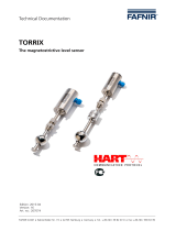 fafnir torrix Technical Documentation Manual
-
Sinclair SWH-300IRE User manual
