Page is loading ...

Maintenance and Troubleshooting manual
DAN-20057317, Rev AE
August 2021
Daniel™ 3410 Series Gas Ultrasonic Flow
Meters
Model 3418

Safety and approval information
This Daniel product complies with all applicable European directives when properly installed in accordance with the instructions in
this manual. Refer to the EU declaration of conformity for directives that apply to this product. The EU declaration of conformity,
with all applicable European directives, and the complete ATEX Installation Drawings and Instructions are available on the internet
at www.emerson.com or through your local Daniel support center.
Information affixed to equipment that complies with the Pressure Equipment Directive, can be found on the internet at http://
www.emerson.com.
For hazardous installations in Europe, refer to standard EN 60079-14 if national standards do not apply.
Other information
Full product specifications can be found in the product data sheet. Troubleshooting information can be found in the user manual.
Product data sheets and manuals are available from the Daniel web site at http://www.emerson.com.
Return policy
Follow Emerson procedures when returning equipment. These procedures ensure legal compliance with government
transportation agencies and help provide a safe working environment for Emerson employees. Emerson will not accept your
returned equipment if you fail to follow Emerson procedures. Return procedures and forms are available on our web support site
at www.emerson.com, or by phoning the Emerson Customer Service department.
Emerson Flow customer service
Email:
•Worldwide: http://[email protected]
•Asia-Pacific: http://[email protected]
Telephone:
North and South America Europe and Middle East Asia Pacific
United States 800 522 6277 U.K. 0870 240 1978 Australia 800 158 727
Canada +1 303 527 5200 The Netherlands +31 (0) 704 136 666 New Zealand 099 128 804
Mexico +41 (0) 41 7686 111 France 0800 917 901 India 800 440 1468
Argentina +54 11 4837 7000 Germany 0800 182 5347 Pakistan 888 550 2682
Brazil +55 15 3413 8000 Italy 8008 77334 China +86 21 2892 9000
Central & Eastern +41 (0) 41 7686 111 Japan +81 3 5769 6803
Russia/CIS +7 495 981 9811 South Korea +82 2 3438 4600
Egypt 0800 000 0015 Singapore +65 6 777 8211
Oman 800 70101 Thailand 001 800 441 6426
Qatar 431 0044 Malaysia 800 814 008
Kuwait 663 299 01
South Africa 800 991 390
Saudi Arabia 800 844 9564
UAE 800 0444 0684
2

Contents
Chapter 1 Maintenance..............................................................................................................5
1.1 Precautions for meter maintenance.............................................................................................5
1.2 Field hydrostatic pressure testing procedures..............................................................................6
1.3 Routine maintenance.................................................................................................................. 7
Chapter 2 Troubleshooting...................................................................................................... 13
2.1 Meter status alarms................................................................................................................... 13
2.2 Troubleshooting the meter........................................................................................................16
2.3 Troubleshoot maintenance log files and trend files.................................................................... 35
Chapter 3 Meter repairs........................................................................................................... 39
3.1 Precautions prior to repairs........................................................................................................39
3.2 T-Slot transducer removal and installation.................................................................................42
3.3 T-Slot transducer holder removal and installation...................................................................... 50
3.4 T-200 transducer assembly removal and installation..................................................................54
3.5 T-200 transducer capsule assembly removal and installation..................................................... 59
3.6 T-200 transducer housing removal and installation....................................................................59
3.7 Transducer cable removal and installation................................................................................. 61
3.8 Replace the meter electronics....................................................................................................67
3.9 Acquisition Board replacement..................................................................................................77
Appendix A Conversion factors................................................................................................... 83
A.1 Conversion factors per units of measurement............................................................................83
A.2 K-Factor and inverse K-Factor conversions.................................................................................84
Appendix B Engineering drawings.............................................................................................. 85
B.1 Daniel 3410 Series Ultrasonic Flow Meter Drawings................................................................... 85
Maintenance and Troubleshooting manual Contents
DAN-20057317 August 2021
Model 3418 GUSM 3

Contents Maintenance and Troubleshooting manual
August 2021 DAN-20057317
4 Maintenance and Troubleshooting manual

1 Maintenance
1.1 Precautions for meter maintenance
This section includes discussion of the maintenance of Daniel 3410 Series Ultrasonic
Meters.
For reference, you may download the Daniel MeterLink Quick Start Manual from: http://
www.emerson.com/en-us/catalog/measurement-instrumentation/daniel-meterlink.
CAUTION
SURFACE TEMPERATURE HAZARD
The meter body and piping may be extremely hot or cold.
Wear appropriate personal protective equipment when coming in contact with the
meter.
Failure to comply may result in injury.
CAUTION
TRANSPORTATION HAZARD
When moving the meter, do not insert the forks of a forklift into the bore.
Inserting the forks may cause the meter to become unstable, resulting in injury or
damage to the bore and sealing face.
CAUTION
TRIPPING HAZARD
Clear all obstacles or obstructions from the work area when transporting, installing or
removing the meter.
Failure to clear the work area may cause injury to personnel.
Maintenance and Troubleshooting manual Maintenance
DAN-20057317 August 2021
Model 3418 GUSM 5

WARNING
CRUSHING HAZARD
Do not remove flange stabilizers.
Attempting to do so could allow the meter to roll, resulting in serious injury or
equipment damage.
A. Flange stabilizers
CAUTION
ESCAPING FLUIDS HAZARD
The purchaser of the meter is responsible for the selection of Daniel components/seals
and materials compatible with the chemical properties of the measurement fluid.
Failure to select suitable meter components/seals may cause escaping fluids, resulting
in injury or equipment damage.
WARNING
HEARING DAMAGE
Wear proper hearing protection before approaching a metering system that is
generating a large amount of audible noise. Obey all facility safety rules.
Failure to comply could result in temporary or permanent hearing loss.
1.2 Field hydrostatic pressure testing procedures
CAUTION
LEAKAGE OR PRESSURE CONTAINING PARTS FAILURE
Use precautions to eliminate hazards to personnel in the event of leakage or failure of
the gas ultrasonic meter pressure containing parts or failure of the test equipment and
to prevent over-pressurization during the test procedure.
Failure to comply may result in injury to personnel or cause damage to the equipment.
1.2.1 T-Slot transducer assembly and mount
Procedure
1. Slowly vent all line pressure on the 3410 Series Gas Ultrasonic Meter to atmosphere.
2. Disconnect transducer cable from the transducer holder.
Maintenance Maintenance and Troubleshooting manual
August 2021 DAN-20057317
6 Maintenance and Troubleshooting manual

3. Loosen the T-Slot transducer assembly with a 1 1/4 inch (32 mm) wrench or socket.
Carefully remove the T-Slot transducer assembly.
4. Place a label on the transducer assembly to marks its location. Port locations are
marked on the transducer cable as well as on cast meter housings.
5. Apply a small amount of Nickel antiseize compound (P/N 3-9960-134) to the
threads of the Hydrotest plug from Hydrotest kit and install it into the mount.
Required kit part numbers are listed below.
Model 3418 Quantity 2 x 1-360-01-220
6. Repeat Step 3 through Step 5 for the other transducer(s) being careful to note the
location of each transducer in the meter assembly.
7. Run the field hydrostatic test.
8. Reverse the steps above to reinstall the transducers into their appropriate ports.
Before reinstalling the transducer assemblies, ensure the transducer ports, mounts,
and transducer holders are clean and free of debris. Apply a small amount of Nickel
antiseize compound to the outer threads of the transducer holders before installing
them into the mounts.
1.2.2 T-200 transducer assembly
Procedure
1. Leave T-200 transducers installed on the 3410 Series Gas Ultrasonic Meter while the
line is pressurized.
2. Run the field hydrostatic test.
1.3 Routine maintenance
Routine maintenance operations requires adherence to all applicable regulations and laws
and safety training for personnel to perform the maintenance operations. Review your
organization's best practices procedures before performing routine maintenance.
1.3.1 Maintenance logs and reports
To monitor the performance health of the meter, and ensure it is operating within
acceptable specifications, routine diagnostics should be performed. Collecting a
maintenance log gives you a snapshot of the current health of the meter and you can
compare the inspection reports from previously saved logs. Use the Logs/Reports menu
and click Maintenance Logs and Reports. Daniel MeterLink™ displays the Maintenance
Logs and Reports dialog box. Choose the time duration, log format and collection rate for
the output file and click the Start button. You can open the file immediately after it is
generated or view it at a later time. It is recommended that a Maintenance log be
collected after an upset in the system.
In establishing a baseline to be used for the trending of the meter diagnostics, it is very
helpful if a set of log files are collected immediately after the meter has been installed in
the field. Preferably, collect the log files at several velocities within the operating range of
Maintenance and Troubleshooting manual Maintenance
DAN-20057317 August 2021
Model 3418 GUSM 7

the meter. This helps establish that the flow profile is relatively constant throughout the
meters operating range (except velocities below 3 ft/sec where the profile may vary).
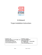
Maintenance log collection
Figure 1-1: Maintenance log collection parameters
Trend maintenance log collection
Merging the results of two or more Maintenance logs into a single file, allows you to build
a historical database of the meter's performance. Trending the logs indicates changes
from the original installation of the meter, or over time. Looking at a single inspection
report, that is either collected monthly or quarterly, can give you an indication of the
meter's health.
Maintenance Maintenance and Troubleshooting manual
August 2021 DAN-20057317
8 Maintenance and Troubleshooting manual

Figure 1-2: Trend log collection
This is important since many diagnostics change slowly overtime. Trending the
maintenance logs helps identify these changes and makes problems much more obvious
than merely viewing a single inspection report. The Trending feature is integral to Daniel
MeterLink™ which allows all important parameters to be trended. Daniel MeterLink
supports trending files in a Microsoft® Excel ® workbook from multiple 3410 Series meter
maintenance logs. Some parameters like gain, signal level,and noise level may show a shift
over time which can be useful in detecting changes in the meter and the installation.
Maintenance logs or Trend files to be trended must all have matching column headings.
This means the logs must be in the same units (i.e. U.S. Customary or Metric), must have
the same pressure type (i.e. gage or absolute), and must have the same time base (1/
second, 1/minute, 1/hour, 1/day). If not, an error message will be displayed stating the
column headings do not match and the file will not be added to the Workbook to trend
list.
Archive log collection
Archive logs may be collected and the options include:
•Daily log - generated every 24 hours on the Contract Hour
•Hourly log - generated every hour at the top of the hour
•Event log - collects the alarm and event log records
Maintenance and Troubleshooting manual Maintenance
DAN-20057317 August 2021
Model 3418 GUSM 9

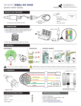
Figure 1-3: Archive log collection parameters
The logs may be collected in a single file or you can choose to collect one type of log. Each
of the Meter Archive logs include the Meter Configuration file.
Maintenance Maintenance and Troubleshooting manual
August 2021 DAN-20057317
10 Maintenance and Troubleshooting manual

1.3.2 Pipe cleaning maintenance
WARNING
BURST HAZARD
Before pipeline cleaning and maintenance ("pigging operations"), remove straightening
vanes or flow conditioners.
Failure to comply may cause excessive pressure in the meter system, resulting in death,
serious injury or equipment damage.
Figure 1-4: 3410 Series Gas Ultrasonic Flow Meter with flow conditioner for uni-
directional flow
Figure 1-5: 3410 Series Gas Ultrasonic Flow Meter with flow conditioner for bi-
directional flow
Straightening vanes or flow profilers must be removed during pipeline cleaning
maintenance operations (“pigging operation”). If the meter run is pigged with a flow
conditioner in line, pressure may build up and cause the pipes and flanges to burst and
severely injure personnel. The excessive pressure may damage the meter or the
transducer ports may collect debris which may impede data acquisition and flow
measurement.
1.3.3 Visual inspection
Periodically inspect the meter and meter run for signs of components loosening or seals
leaking. This includes:
Procedure
1. Fluids leaking from seals. This could be visually noticed for liquids leaking. It may be
audible for gasses leaking. Ice may also form at a point of a gas leak.
Maintenance and Troubleshooting manual Maintenance
DAN-20057317 August 2021
Model 3418 GUSM 11

2. Movement of components that should be rigid.
3. Excessive noise due to vibration could be sign of a loose component.
Inspection should be more frequent in systems with a large amount of vibration.
Maintenance Maintenance and Troubleshooting manual
August 2021 DAN-20057317
12 Maintenance and Troubleshooting manual

2 Troubleshooting
2.1 Meter status alarms
Run Daniel MeterLink™ and open the Meter Monitor (Summary) view to perform a
diagnostics health check.
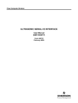
Figure 2-1: Meter Monitor status alarms
If the meter is measuring flow and operating within the calibration parameters the Meter
Status LED is green. If the Meter Status LED is red, an active alarm exists that requires you
to take corrective action. Click the Check Status button to display the Status Summary
screen. The alarms are shown with the primary causes listed first. Click the question mark,
, next to the alarm to display a help topic related to the alarm and recommended actions
to resolve the issue.
Maintenance and Troubleshooting manual Troubleshooting
DAN-20057317 August 2021
Model 3418 GUSM 13

Figure 2-2: Status summary
2.1.1 Check status
Click the Check Status button if any of the LEDs are yellow or red to see more specific
information causing the status alarm. Some alarms do not require an acknowledge and
will clear automatically when the alarm condition goes away. Alarms that require a user to
acknowledge them will have a button to the right titled ACK. Clicking the ACK button
changes the button text to Wait and sends a request to the meter to clear the alarm. The
alarm will disappear from the Check Status dialog once the alarm actually clears.
Click the Check Status button and Daniel MeterLink™ opens the Status Summary dialog
box that gives a short description of all alarms present.
Figure 2-3: Status Summary
A. Active alarm conditions from Meter Monitor page
B. Status summary page with alarm examples
Following is a list and a brief description of the types of alarms:
•System
•Power Loss
Troubleshooting Maintenance and Troubleshooting manual
August 2021 DAN-20057317
14 Maintenance and Troubleshooting manual

•Field I/O
•Validity
•Comms
•Check Status
2.1.2 System alarm
The System alarm indicates a failure in the hardware that should be addressed by a service
technician. This includes memory checksum errors and communication errors within the
hardware. A Red LED indicates a system alarm condition. Collect a Maintenance log and an
audit/alarm log and then, contact your Daniel service representative. This could be an
alarm condition that occurred and remains latched until the condition is resolved and the
alarm is cleared by clicking the ACK button on the Monitor → Check Status → Status
Summary page.
2.1.3 Chord A, Chord B, Chord C, Chord D, Chord E, Chord F,
Chord G and Chord H alarm
Chord A, Chord B, Chord C, Chord, D, Chord E, Chord F, Chord G and Chord H - These
alarms indicate how a chord is functioning.
Table 2-1: LED colors
LED Color Problem
Green No alarms are present. Chord is operating properly.
Yellow The chord has failed or is in acquisition. This chord is not used for this batch. Chord
that have failed or are shown to be in acquisition for repeated batches indicates that
the meter should be inspected by a service technician. The chord has manually been
set to inactive. At least one sample in the batch caused an alarm but it did not cause
the chord to fail. The sample will not be used in the batch. Discarding occasional
samples can occur during normal operation such as during flow velocity changes.
Red The in-use length is not equal to the calculated length for chord. If this is a new
meter or an upgraded meter, check that the chord length and correct if needed. If
incorrect, check all meter parameters against the meter Zero Flow Calibration
report. This report can be requested from your local area Daniel service
representative.
Gray The chord has manually been set to inactive.
2.1.4 Field I/O alarm
Reports various field I/O devices that are in alarm. Click the Check Status button for more
details on specific alarms. The field is grayed out if the Daniel 3410 Series Ultrasonic Gas
Flow Meter does not support this alarm.
Maintenance and Troubleshooting manual Troubleshooting
DAN-20057317 August 2021
Model 3418 GUSM 15

2.1.5 Validity alarm
This alarm indicates that the meter may not be measuring accurately. Click Check Status
to see a description of which validity alarms are active. The validity alarms QMeter and
QFlow indicate an issue with the meter collecting enough information from the chords to
make an accurate measurement. The validity alarms for pressure and temperature
indicate that the value is above or below the alarm limits for these values. Red and green
are the only colors used for this alarm.
2.1.6 Comms alarm
The Comms alarm indicates that communications between Daniel MeterLink™ and the
meter failed. This could be due to a poor communication link. Daniel MeterLink continues
to retry communications. Red and green are the only colors used for this alarm.
2.1.7 Communications
The Communications Analyzer (via Daniel MeterLink™ Tools → Menu → Communications
Analyzer menu path) displays communications between Daniel MeterLink and the
ultrasonic meter. This utility is useful for troubleshooting communications to the meter. It
displays many of the TCP/IP commands between Daniel MeterLink and the connected
meter.
2.2 Troubleshooting the meter
Table 2-2 and the following sections show errors that may occur with the meter hardware,
firmware or connections and recommend actions to resolve the problem(s).
Table 2-2: Troubleshooting
Error Recommended action(s)
Acquisition Module Error •Check/Replace I.S. Barrier.
•Check/Replace Acquisition module.
•Attempt the Program Download procedure to install the firmware.
—Cycle power to the meter
—Replace the Acquisition Module.
—If the Acquisition Module cannot be reprogrammed, collect a
complete Archive log and contact your local area Daniel service
representative.
Acquisition Module is not
compatible with
firmware
•Check Acquisition Module is compatible with Model # configured in
meter (i.e. 3414 4-path or 3418 8-path).
•Replace the Acquisition Module.
Troubleshooting Maintenance and Troubleshooting manual
August 2021 DAN-20057317
16 Maintenance and Troubleshooting manual

Table 2-2: Troubleshooting (continued)
Error Recommended action(s)
Chord failure •Chord is hard failed, and meter is unable to obtain measurement
data from a pair of transducers.
—If a chord is failed and no other transducers are failed or are
reporting status alerts, the issue is most likely isolated to this
pair of transducers or its cabling. Check the transducer wiring
for this pair of transducers to make sure connections are secure
and wired correctly.
—Remove the transducer cable from the transducer and measure
the resistance with an Ohm meter.
•For T-11 and T-12 transducers, remove the transducer cable
from the transducer and measure the resistance with an
ohm meter across the two pins on the back of the
transducer holder. If the value is over 2 ohms, replace the
transducers.
•For T-21, T-22, T-32 and T-41 transducers, remove the
transducer cable and transformer assembly and measure
the resistance with an ohm meter. If the value is not 1
Mohm +/- 0.2 Mohm, try cleaning the pins with alcohol and
a small object like a toothpick to see if that lowers the
resistance. If not, replace the transducers. Measure the
resistance across the two pins on the transformer module
that lead to the electronics. If the value is over 2 ohms,
replace the transformer module. Measure the resistance
across the two pins on the transformer module that lead to
the electronics. If the value is over 2 ohms, replace the
transformer module. Measure the resistance across the two
pins on the transformer module that lead to the transducer.
If the value is not between 30 and 40 ohms for the T-21 and
T-41 transformer module, replace the transformer module.
If the value is not between 50 and 75 ohms for the T-22
transformer module, replace the transformer module. If the
value is not between 7 and 12 ohms for the T-32
transformer module, replace the transformer module. If
possible, measure the capacitance of the transducer with an
LCR meter. If the value is not between 450 and 600 pF for
the T-21 and T41 transducer, replace the transducer. If the
value is not between 215 and 350 pF for the T-22
transducer, replace the transducer. If the value is not
between 400 and 550 pF for the T-32 transducer, replace
the transducer.
•For T-200 transducers, remove the transducer cables from
the transducers and measure the resistance with an ohm
meter across the two pins on the back of the transducer
capsules. If the values are over 2 ohms, replace the
transducer capsules. If the values are under 2 ohms, remove
the transducer capsules, clean and reapply the coupling
fluid to the front face of the transducer capsules, and
reinstall the transducer capsules. If this does not correct the
issue, replace the transducer capsules.
Maintenance and Troubleshooting manual Troubleshooting
DAN-20057317 August 2021
Model 3418 GUSM 17

Table 2-2: Troubleshooting (continued)
Error Recommended action(s)
—If transducer cabling allows, swap cabling of failed transducer
pair with a pair with equal path lengths. If the alarm remains
active for this chord, then the transducers are working properly.
If this alarm clears but the chord that was swapped now fails,
the issue is with the transducer.
—Collect a Maintenance Log, Configuration file and Waveform
stream file with Daniel MeterLink and contact your Daniel
service representative.
CPU Module LINK LED •When connecting directly:
—Check the cross-over cable connection (P/N 1-360-01-596)
•When using a Hub:
—Use straight-through patch cable between the meter and the
hub and a straight-through patch cable between the hub and
the PC.
—Do not connect either the Daniel 3410 Ultrasonic Flow Meter or
PC to the hub UPLINK port.
—Check the CPU Module LED 1 is on (either solid red or flashing
green). If the LED is not on, check power to the meter.
—If the LED is on, check the Ethernet cable connections.
CPU Module LINK LED is
on but I can't
communicate with the
meter using Ethernet
•If you are connecting for the first time, refer to the 3410 Series
Installation Manual, (DAN-20057315) in "Wiring and inputs/
outputs" for instructions on initial communication (via Ethernet)
setup.
•Enable the DHCP switch on the CPU Module.
•Verify that the PC has received an IP address from the meter as
follows:
—Bring up DOS prompt window (Start → Run → (type)cmd)
—In the DOS prompt window, type ipconfig
•If you get the following: IP 192.168.135.35 (note: the last .35 can
be up to .44) with a Subnet Mask of 255.255.255.0 and Default
Gateway you should be able to connect to the meter.
•If you get the following:
—Ethernet adapter Local Area Connection 1
—IP Address: 0.0.0.0 the PC has not yet received an IP address
from the DHCP server wait (up to 30 seconds).
—If after 30 seconds the PC has not received an IP address from
the DHCP server or the IP address shown above (from ipconfig)
is different from the range of 192.168.135.35 through
192.168.135.44, verify that the PC is configured to receive its IP
address automatically (via DHCP).
Troubleshooting Maintenance and Troubleshooting manual
August 2021 DAN-20057317
18 Maintenance and Troubleshooting manual

Table 2-2: Troubleshooting (continued)
Error Recommended action(s)
Communication line
connected to the flow
computer but no signal is
received
•Check for loose connections at the flow meter and the flow
computer.
•Check the CPU Module settings.
Communication issues
due to blocked network
ports
•Blocked network ports on the computer running Daniel MeterLink
or on a company LAN can prevent connections to the meter or
prevent certain features from working. These issues may occur over
Ethernet, Modem and Direct serial connections. Reference the list
of network ports used by Daniel MeterLink in the Help file and the
symptoms of having blocked ports. Contact your IT department for
assistance in resolving these issues.
•Error condition of a blocked network:
—Cannot connect to a meter
—Cannot collect Archive log files
—Cannot view or stream waveforms in Waveform Viewer or
Signal Analyzer
—Cannot upgrade firmware
—Communications lost over serial or modem connections while
Daniel MeterLink is idle on a screen.
•Symptoms of blocked network:
—If a PING is blocked on this network port, serial or modem
connections could be lost after approximately 15 seconds of
inactivity. This issue can be confirmed by checking the
log_meter_log_file in the Temp data folder. The path of the
Temp data folder is shown in the Daniel MeterLink About dialog.
—A blocked FTP port will generally not prevent a connection to
the meter, but will prevent log collections and program
downloads. A blocked FTP port could prevent a connection in
the event the meter is running a newer version of firmware for
which Daniel MeterLink does not currently have a database
configuration file. If this is a case, a message stating “Error
reading database config file dbconfig<databaseversion>.xml
from the meter.” will be displayed.
—A blocked DB API port will report “Error 10001 opening
database connection to <IP address>”.
—A blocked Streaming port will report an error message “Unable
to open a control socket”. This will occur when opening the
Signal Analyzer window or clicking Read or Stream to File in the
Waveform Viewer.
Communicating with
meter but all chords
display failures
•Verify that the resistance of transducers is within Specification (2
Ω).
•Check the Acquisition Module.
•Check the interconnect cables between the Base assembly and the
Transmitter Electronics Enclosure.
Maintenance and Troubleshooting manual Troubleshooting
DAN-20057317 August 2021
Model 3418 GUSM 19

Table 2-2: Troubleshooting (continued)
Error Recommended action(s)
Cannot communicate
with Daniel MeterLink
program
•Ensure that the meter is properly powered.
•Ensure that the computer cable is properly connected and check
your interface pins (RS-485 or RS-232).
•Verify that the communication parameters of the Daniel MeterLink
program are correctly set.
•Check RS-485 or RS-232 communication LEDs.
Connect to multiple
meters via Ethernet when
they are on the same LAN
•Configure each meter with a unique user-specified IP address
(following the initial communication quick start instructions the
3418 Installation manual (P/N DAN-20057315) in "Serial
connections").
•Contact your IT department for valid IP addresses for your LAN and
Gateway addresses.
•Disable the DHCP server.
Connect to multiple
meters via Ethernet when
they are on the same hub
but not connected to an
intranet LAN
•Configure each meter with a unique user-specified IP address
following the initial communication quick start instructions (the
3418 Installation manual (P/N DAN-20057315) in "Serial
connections").
•Assign each meter on the hub a unique IP address within the range
192.168.135.150 through 192.168.135.254 (Gateway address for
each meter may be left unconfigured as 0.0.0.0).
•A PC may receive its IP address from an external DHCP server; in this
case, one and only one meter must have its DHCP server enabled
(the DHCP server will serve up to 10 IP addresses to PCs attempting
to talk to all meters on the hub).
•Once a meter's IP address is configured, the meter may be
connected to the hub and accessed using that IP address.
Configuration changed •One or more parameters have been modified in the meter's
configuration,
—Collect an Audit log using Daniel MeterLink in order to see what
configuration parameters changed and when they changed.
—Run the Tools → Edit/Compare Configuration utility and select
Write All or Write Checked values to write the changes to the
meter.
—Save the configuration file.
Configuration lost •The meter configuration has reset to default values and the meter is
not configured correctly to measure flow and the meter has
performed a Cold Start.
—Unless the Cold Start occurred after upgrading firmware,
replace the CPU board.
—If the cold start occurred after a firmware upgrade, fully re-
configure the meter from a previously saved configuration
using the Tools → Edit/Compare Configuration in Daniel
MeterLink.
Troubleshooting Maintenance and Troubleshooting manual
August 2021 DAN-20057317
20 Maintenance and Troubleshooting manual
/